Table of Contents
Advertisement
O W N E R ' S
TABLE OF CONTENTS:
Introduction - Pg. 1
Safety Precautions - Pg. 2
Assembly for AP-250S_AP-250D
Pg. 3 - Pg.23
Cable Adjustments - Pg. 22
Cable Mapping Diagrams
Pg. 24 - Pg. 29
Parts List - Pg. 31
Exploded View Diagram
Fold-Out Pg. 32
Pg. 33 - Pg. 36
Maintenance - Pg. 37
Optional Stations - Pg. 38 - Pg. 39
Warranty - Back Page
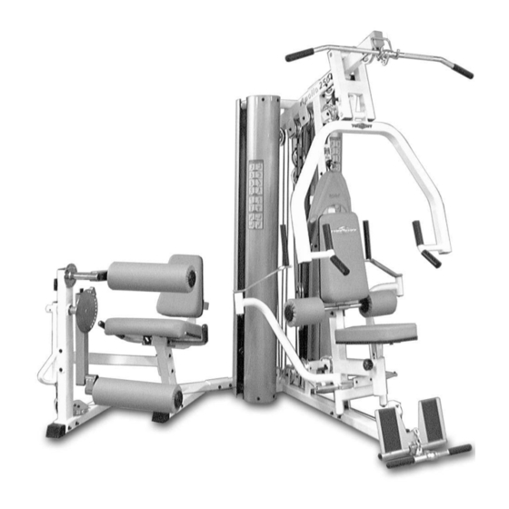
Apollo 2-Stack Gym System
Includes Assembly for:
AP-250S
Apollo 2-Stack Gym System (Standard)
AP-250D
Apollo 2-Stack Gym System (Deluxe)
A m e r i c a ' s
P r e m i u m
M A N U A L
100"
E x e r c i s e
E q u i p m e n t
Revision Date 06-12-03
72"
L 72" W 100" H 83"
Advertisement
Table of Contents

Related Manuals for TuffStuff AP-250S


Summary of Contents for TuffStuff AP-250S
- Page 1 Maintenance - Pg. 37 Optional Stations - Pg. 38 - Pg. 39 Warranty - Back Page Revision Date 06-12-03 Apollo 2-Stack Gym System Includes Assembly for: AP-250S 100” Apollo 2-Stack Gym System (Standard) AP-250D Apollo 2-Stack Gym System (Deluxe) 72”...
- Page 2 Stuff Equipment This Tuffstuff product has been built to precise quality standards Caution indicates a potentially hazardous situa- and has been carefully packaged to ensure that damage will not tion, which, if not avoided, may result in minor or occur during shipment.
-
Page 3: Safety Precautions
Safety Precautions afety irst Regardless of how enthusiastic you may be about getting on 4. Use proper discretion when children are present. your equipment and exercising, take the time to ensure that your safety is not jeopardized. A moment’s lack of attention 5. - Page 4 IG. 4 On a flat surface, lay the Base Frame (#2) down and attach FIG. 5 Using a rubber mallet, insert two Plastic Insert Caps 2” Sq hree Pulleys 4 1/2 Rd (#68-Labeled D1,E1,E3) to the Base Frame (#2) (#85) into the tube-ends of the Base Frame (#2).
- Page 5 Owner’s Manual: Assembly Instructions IG. 8 Using a rubber mallet, insert one Plastic Insert Cap w/ Groove FIG. 9 Using a rubber mallet, insert two Plastic Insert Caps w X 3 (#57) onto the tube-end of Rear Upright (#4). Next, attach the Groove 2 X 3 (#57) onto the tube-ends of the Leg Extension Mai Rear Upright (#4)
- Page 6 IG. 12 Next, attach the Leg Extension Arm Support (#13) to the FIG. 13 Attach the Leg Extension Right Handle (#45) and the eg Extension Front Frame (#11) using two Hex Head Cap Screws Extension Left Handle (#46) to the Leg Extension Seat Frame (#12 /8-16 X 4 1/4 (#104), four Flat Washers SAE 3/8”...
- Page 7 Owner’s Manual: Assembly Instructions IG. 16 Attach the Actuator Arm (#43) to the axle of the Circular FIG. 17 Next, attach the Top Adjustable Leg Holder Tube (#32) late (#16). Next, align the hole of the Actuator Arm (#43) with the Leg Extension Front Frame (#11) using one Hex Head Cap Screw ole of the axle of the...
- Page 8 IG. 20 Caution: It is strongly recommended to use another FIG. 21 Next, attach the Top Pulley Assembly (#5) to the person in assisting with this assembly. Upright (#4) using two Hex Head Cap Screws 3/8-16 X 3 1/4 (#106) four Flat Washers SAE 3/8”...
- Page 9 Owner’s Manual: Assembly Instructions IG. 24 Insert the Left Pec Dec Arm (#7) along with the Aluminum FIG. 25 Secure the Left Pec Dec Arm (#7) into place using on Cam Plate (#144) into the receptacle of the Front Upright (#3).
- Page 10 IG. 28 Using a rubber mallet, insert one Pivot Axle 1 X 8 1/8 (#18) FIG. 29 Using a rubber mallet, insert two Plastic Insert Caps 2” Sq hrough the holes of the Press Bar Selector Housing (#17) (#86) into the tube-ends of the Press Bar (#1).
- Page 11 Owner’s Manual: Assembly Instructions IG. 32 Insert the four Guide Rods 3/4 X 72 (#21) into the FIG. 33 Carefully begin sliding the Weight Plates over the Guid eceptacles of the Base Frame (#2), as shown above. Next, insert four Rods (#21) beginning with the five 15 Lb.
- Page 12 MASKING TAPE IG. 36 To attach the Decal-Numbers we recommend using a piece of FIG. 37 Next, attach the Selector Pins w/Coil (#83) to the Selecto masking tape as a guide to vertically align the Decal-Numbers. Attach the Bars (#24). Decal Weight Numbers (#116) to the Weight Plates (#133, #23, #134) in he corresponding order.
- Page 13 Owner’s Manual: Assembly Instructions IG. 40 Next, thread one Adjustable Stopper (#33) into the threaded FIG. 41 Locate the two Closed-End Double Pulley Brackets (#26 ocket located on the Top Pulley Housing (#5), as shown in the left and attach four Pulleys 4 1/2 Rd. (#68) using four Hex Head Ca icture above.
- Page 14 IG. 44 Route the Leg Extension Cable (#41) up and over the FIG. 45 Next, locate the assembled Adjustable Double Pulle ulley 4 1/2 Rd. (#68-Labeled A4) located on the Top Pulley Housing Plates (#27) and route the Leg Extension Cable (#41) down an #5).
- Page 15 Owner’s Manual: Assembly Instructions IG. 48 Next, continue to route the Leg Extension Tension Cable FIG. 49 Attach the end of the Leg Extension Tension Cable (#42 #42) up and over the Pulley 4 1/2 Rd. (#68-Labeled B1). to the threaded socket of the Base Frame (#2) using one Split Bolt 1/2 13 X 1 (#94), and one Split Lock Washer 1/2”...
- Page 16 IG. 52 Next, continue to route the Lat Cable (#37) around the FIG. 53 Next, continue to route the Lat Cable (#37) over the Pulley ulley 4 1/2 Rd. (#68-Labeled C3), then across and over the Pulley 4 1/2 Rd. (#68-Labeled C5), then through the Front Upright (#3) /2 Rd.
- Page 17 Owner’s Manual: Assembly Instructions IG. 56 Next, begin routing the Low Row/Abdominal Cable (#38) FIG. 57 Continue to route the Low Row/Abdominal Cable (#38 etween the Pulley 4 1/2 Rd. (#68–Labeled D1) and the Hex Head Cap through the slots of the Front Upright (#3) and the Base Frame (#2...
- Page 18 IG. 60 Attach the Abdominal Strap (#65), one Nylon Ball 1 3/4 X FIG. 61 Attach one end of the Pec Dec Cable (#39) to the Alum /16 (#119), and one Strap Bracket #20 (#118) to the Low Row/ num Cam Plate (#144) and secure it onto place using one Socke Abdominal Cable (#38) using one Shoulder Bolt 3/8 X 3/4 (#117), and...
- Page 19 Owner’s Manual: Assembly Instructions IG. 64 Route the Tension Cable (#40) up and over the Pulley 4 1/2 FIG.65 Secure the end of the Tension Cable (#40) to the Rd. (#68-Labeled F1) on the Closed-End Pulley Bracket (#26). Next, Frame (#2) using one Strap Bracket #20 (#118), one Shoulder Bolt 3/ oute the cable down and under the Pulley 4 1/2 Rd.
- Page 20 IG. 68 Attach Leg Extension Seat Pad (#48) to the Leg Exten- FIG. 69 Next, insert one of the Foam Rolls 2 X 5 1/2 X 16 (#51) ion Seat Frame (#12) using four Hex Head Cap Screws 3/8-16 X 1 Top Adjustable Leg Holder Tube (#32) and secure it into plac /4 (#112), and four Flat Washers SAE 3/8”...
- Page 21 Owner’s Manual: Assembly Instructions IG. 72 Next, insert the Foot Roll Tube 1 X 27 (#30) into the FIG. 73 Insert two Foam Rolls 1 X 5 1/2 X 7 1/4 (#52) to the tube eceptacle of the Adjustable Back Pad Bracket (#10).
- Page 22 IG. 76 Insert a Rubber Grip (#121) over each one of the tube-ends FIG. 77 Next, attach one Snap Link (#124) to the Lat Cable (#37 using one Shoulder Bolt 3/8 X 3/4 (#117), and one Nylon Insert Loc f the Low Row Bar 20” (#63), and the Lat Bar 48” (#62), as shown Nut 5/16-18 (#102).
- Page 23 AP-250S_AP-250D CABLE ADJUSTMENT DIAGRAM The Diagram below depicts the location of the cable adjustments on each Caution: The cables should be inspected and adjusted periodi cally to avoid any slack in the cables which would, consequently workstation. It is imperative that you maintain the cables’ proper adjust- ment to ensure a safe and smooth operation.
- Page 24 IG. 80 After the cables have been adjusted, proceed to attach the FIG. 81 Next, attach the bottom of the four Weight Shrouds (#22 Weight Shrouds (#22) to the two Guide Rod Retainers (#20). to the Base Frame (#2) using eight Hex Head Cap Screws 1/4-20 X 3/ sing eight Hex Head Cap Screws 1/4-20 X 3/4 (#114), and eight Flat (#114), and eight Flat Washers 1/4 (#97).
- Page 25 AP-250S_AP-250D Apollo 2-Stack Gym System...
- Page 26 AP-250S_AP-250D Apollo 2-Stack Gym System...
- Page 27 AP-250S_AP-250D Apollo 2-Stack Gym System...
- Page 28 AP-250S_AP-250D Apollo 2-Stack Gym System...
- Page 29 AP-250S_AP-250D Apollo 2-Stack Gym System...
- Page 30 AP-250S_AP-250D Apollo 2-Stack Gym System...
- Page 31 FIG. 83 FIG. 84 132 111 FIG. 85 FIG. 86 FIG. 87 AP-250S_AP-250D Apollo 2-Stack Gym System...
- Page 32 BNH0079 RUBBER CORR MAT 1/8" X 1 1/2 X 5 BNH1226 LABEL-ADJUSTMENT POSITION BACK PAD 9/16 X 7.5 BNH0080 AP-250D Parts List All parts same as AP-250S, except for parts listed below Item No. Description Part No. Item No. Description Part No.
- Page 33 Adjustment Features Press Bar (#1) settings ♦ Used for Shoulder Press Exercise. Settings A,B,C,D ♦ Used for Chest Press Exercise. Settings E,F,G ♦ Used for Seated Row Exercise. Settings G,H,I Press Bar (#1) adjustment: 1. Grasp the Press Bar (#1) 2.
- Page 34 Adjustment Features Leg Extension Pivot–Arm (#25) adjustment: 1. Grasp the Pivot-Arm (#25). 2. Pull the Push-Pull Pin 1/2 X 2 3/4 (#137) to release Pivot-Arm (#25). 3. Keep the Push-Pull Pin (#137) released and adjust Pivot-Arm (#25) to the desired position. 4.
- Page 35 Adjustment Features Bench Press Seat Pad (#35) adjustment: Low Row Foot Support (#15) adjustment: 1. Grasp the Bench Press Seat Pad (#35). 1. Grasp the Low Row Foot Support (#15). 2. Turn counterclockwise then pull the Turn Pull Pin w/Knob (#138) to 2.
- Page 36 Adjustment Features The picture to the left shows the Pec Dec Arms (#6,#7) and the Pec Dec Swival Handles (#8) adjusted to the inside of the unit to allow the Press Bar (#1) to move freely during the seated rowing exercise. Caution: The Left Pec Dec Arm (#7) and the...
- Page 37 Maintenance aintenance Information 1. Lubrication of all moving parts is essential to the longevity and optimal performance of your Home Gym. Initial Correct lubrication of some parts of your gym have been done at the factory, but the weight stack guide rods must be lubricated at the time of assembly.
- Page 38 Optional Stations AP-2LP Side Mount Configuration AP-2TO Rear Mount Configuration 72” W 130” H 83” L 126” W 100” H 83” 100” 130” 126” 72” AP-2AB Side Mount Configuration AP-2AB Rear Mount Configuration 72” W 121” H 83” L 113” W 100” H 83” 113”...
- Page 39 Optional Stations AP-250 + AP-2LP + AP-2TO AP-250 + AP-2LP + AP-2AB 126” W 130” H 83” L 113” W 130” H 83” 30” 130” 126” 113” AP-250 + AP-2AB + AP-2TO 126” W 121” H 83” 121” 126” AP-250S_AP-250D Apollo 2-Stack Gym System...
- Page 40 TuffStuff. Limitations: The foregoing shall constitute the sole remedy of the purchaser and the sole liability of TuffStuff with regard to warranty, whether express or implied by operation of law or otherwise, including but not limited to any implied warranties of merchantability or fitness.
Need help?
Do you have a question about the AP-250S and is the answer not in the manual?
Questions and answers
I need help with installation ..... can I hire someone to come to my home please