Table of Contents
Advertisement
O W N E R ' S
TABLE OF CONTENTS:
Introduction - Pg. 1
Safety Precautions - Pg. 2
Assembly for TS-1000 - Pg. 3 - Pg. 23
Cable Adjustments - Pg. 22
Pg. 24 - Pg. 29
Parts List - Pg. 31
Exploded View Diagram
Fold-Out Pg. 32
Adjustment Features - Pg. 33 - Pg. 34
Maintenance - Pg. 35
Warranty - Back Page
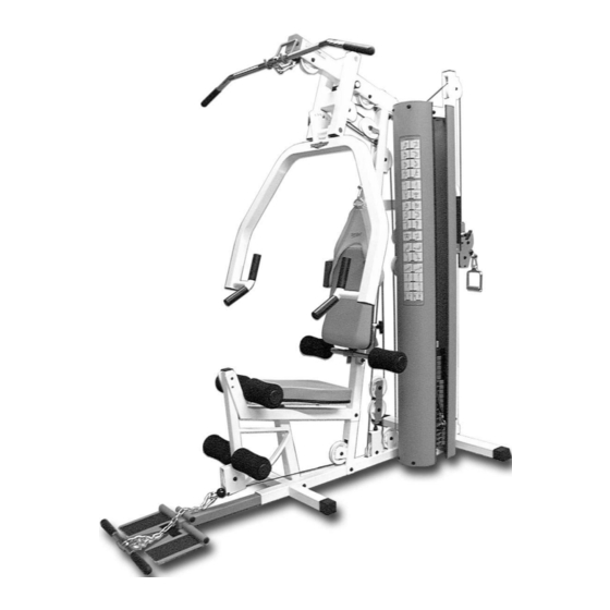
TS-1000
Home Gym w/Adjustable
High-Low Pulley System
A m e r i c a ' s
P r e m i u m
M A N U A L
48"
L 108" W 48" H 83"
E x e r c i s e
E q u i p m e n t
Revision Date 10-16-01
108"
Advertisement
Table of Contents

Related Manuals for TuffStuff TS-1000


Summary of Contents for TuffStuff TS-1000
- Page 1 M A N U A L TABLE OF CONTENTS: Introduction - Pg. 1 Safety Precautions - Pg. 2 Assembly for TS-1000 - Pg. 3 - Pg. 23 Cable Adjustments - Pg. 22 Cable Mapping Diagrams Pg. 24 - Pg. 29 Parts List - Pg.
- Page 2 TS-1000 in the area where it is to be used upon completion. Hardware Measurement Diagram 3. It is recommended that another person assist you with the assembly this unit.
-
Page 3: Safety Precautions
-1/2 (#56), Push Pull Pins 1/2” X 5-5/8 (#58), and the Turn/Pull Pin w/ Knob (#57) on this unit. Fig. 3 Caution: Check the Turn/Pull Pin w/Knob (#57) to be full engaged into the selected hole of the Adjustable Seat Frame (#37). TS-1000 Home Gym w/Adjustable High-Low Pulley System... - Page 4 Foot Roll Tube 1 x 16 (#4). Note: When positioning the Base Frame (#1) consider the complete area surface of the TS-1000. Use the overhead view on NOTE: the cover page for designing your layout before assembling. IG. 6 Next, attach the...
- Page 5 Nylon Insert Jam Lock Nut 3/8-16 (#93). NOTE: Diagram on pages 21-29. These black boxed letters will be primarily used for locating certain pulleys during the cable routing process beginning with Fig. 11. TS-1000 Home Gym w/Adjustable High-Low Pulley System...
- Page 6 Hex Head Cap Screws 1/4-20 x 1 1/2 (#104), and two Nylo /8” (#87), and one Nylon Insert Jam Lock Nut 3/8-16 (#93) Insert Lock Nuts 1/4-20 (#95) to the High-Low Double Pulley Bracke (#15), in the positions indicated by the black arrows. TS-1000 Home Gym w/Adjustable High-Low Pulley System...
- Page 7 SAE 3/8” (#87), and two Nylon Insert Lock Nuts 3/8-16 (92). Loosely Fasten: Do not completely fasten this hardware assem- bly at this time, as it will be completely fastened later in the as- sembly process. OSELY FASTEN TS-1000 Home Gym w/Adjustable High-Low Pulley System...
- Page 8 Pivot Axle 1 X 8 1/8 (#24) into the Press Ba NOTE: assembled by the factory. Selector Housing (#23) and through the Press Bar (#25) until it is flus with both sides of the Press Bar Selector Housing (#23). TS-1000 Home Gym w/Adjustable High-Low Pulley System...
- Page 9 Base Frame (#1), as shown above. tom, the nine 10 Lb. Weight Plates (#18) in the middle, and the five 5 Lb Weight Plates (#19) on top of the weight stack. TS-1000 Home Gym w/Adjustable High-Low Pulley System...
- Page 10 (#112), four Flat Washers SAE 3/8” (#87), and two Nylon Insert Lock Nut 3/8-16 (#92). Loosely Fasten: Do not completely fasten this hardwar assembly at this time, as it will be completely fastened later in th assembly process. LOOSELY FASTEN TS-1000 Home Gym w/Adjustable High-Low Pulley System...
- Page 11 (#84) to allow adjustment for cables tension later in the assembly process Loosely Fasten: Do not completely fasten this hardware assem- bly at this time, as it will be completely fastened later in the as- sembly process. OSELY FASTEN TS-1000 Home Gym w/Adjustable High-Low Pulley System...
- Page 12 Nylon Pulley 4 1/2 Rd. detailed illustration of the Lat Cable (#33) routing. NOTE: #67-Labeled A1). Note: Refer to the Cable Mapping Diagram on page 24 for further detailed illustration of the Lat Cable (#33) routing. NOTE: TS-1000 Home Gym w/Adjustable High-Low Pulley System...
- Page 13 Note: Refer to the Cable Mapping Diagram on page 24 for further Note: Refer to the Cable Mapping Diagram on page 24 for furthe detailed illustration of the Lat Cable (#33) routing. detailed illustration of the Lat Cable (#33) routing. NOTE: NOTE: TS-1000 Home Gym w/Adjustable High-Low Pulley System...
- Page 14 Note: Refer to the Cable Mapping Diagram on page 25 for furthe Note: Refer to the Cable Mapping Diagram on page 25 for further detailed illustration of the Leg Extension/Abdominal Cable (#34 NOTE: routing. detailed illustration of the Leg Extension/Abdominal Cable (#34) NOTE: routing. TS-1000 Home Gym w/Adjustable High-Low Pulley System...
- Page 15 Nylon Insert Lock Nut 1/4-20 (#95). Refer to Fig. C on page 25 or further illustration of this hardware assembly. Note: Refer to the Cable Mapping Diagram on page 25 for further detailed illustration of the Leg Extension/Abdominal Cable (#34) NOTE: routing. TS-1000 Home Gym w/Adjustable High-Low Pulley System...
- Page 16 Note: Refer to the Cable Mapping Diagram on page 26 for further detailed illustration of the High-Low Cable (#35) routing. Note: Refer to the Cable Mapping Diagram on page 26 for furthe NOTE: detailed illustration of the High-Low Cable (#35) routing. NOTE: TS-1000 Home Gym w/Adjustable High-Low Pulley System...
- Page 17 Note: Refer to the Cable Mapping Diagram on page 26 for further (#67-Labeled C9). detailed illustration of the High-Low Cable (#35) routing. NOTE: Note: Refer to the Cable Mapping Diagram on page 26 for furthe detailed illustration of the High-Low Cable (#35) routing. NOTE: TS-1000 Home Gym w/Adjustable High-Low Pulley System...
- Page 18 Note: Refer to the Cable Mapping Diagram on page 27 for further Note: Refer to the Cable Mapping Diagram on page 27 for furthe detailed illustration of the Tension Cable (#36) routing. detailed illustration of the Tension Cable (#36) routing. NOTE: NOTE: TS-1000 Home Gym w/Adjustable High-Low Pulley System...
- Page 19 Turn/Pull Pin w/Knob (#557) as you begin inserting th hown above, using two Hex Head Cap Screws 3/8-16 X 1 3/4 (#102), assembled Adjustable Seat Frame (#37) into the Leg Extension Benc nd two Flat Washers SAE 3/8” (#87). Frame (#9). TS-1000 Home Gym w/Adjustable High-Low Pulley System...
- Page 20 Adjustable Back Pad Bracket (#7) using a Set Screw 1/4-20 X 1/4 #53), as shown above. Use the supplied Hex Key 1/8” (#115) to properly ecure the Set Screw 1/4-20 X 1/4 (#53) into place. TS-1000 Home Gym w/Adjustable High-Low Pulley System...
- Page 21 Connect the Lat Bar 48” (#41) to the Lat Cable (#33) using the Snap Lin (#110). Use the Lat Bar Holder (#26) to rest the Lat Bar 48” (#41) onto when not in use TS-1000 Home Gym w/Adjustable High-Low Pulley System...
- Page 22 Low Cable (#35) to the Leather Ankle Strap (#43) using the Snap Lin rly. (#110). Note: Refer to the High-Low Cable Mapping Diagram on page 26 for further illustration of this assembly. NOTE: TS-1000 Home Gym w/Adjustable High-Low Pulley System...
- Page 23 Pulley Bracket (#32) once the cable adjust ment is complete. Fully Fasten: Proceed to Fully Fasten these hardware assemblies and all of the previous assem blies that were left loosely fastened. FULLY FASTEN TS-1000 Home Gym w/Adjustable High-Low Pulley System...
- Page 24 0 X 3/4 (#105), and four Nylon Flat Washers 1/4” (#78). Refer to the Ex- tion of this assembly. loded View Diagram on Fold out page for further illustration of this as- embly. Fully Fasten: Proceed to align and fully fasten these hardware as semblies. FULLY FASTEN TS-1000 Home Gym w/Adjustable High-Low Pulley System...
- Page 25 TS-1000 Home Gym w/Adjustable High-Low Pulley System...
- Page 26 TS-1000 Home Gym w/Adjustable High-Low Pulley System...
- Page 27 TS-1000 Home Gym w/Adjustable High-Low Pulley System...
- Page 28 CABLE MAPPING DIAGRAM FOR: Tension Cable #36 TS-1000 Home Gym w/Adjustable High-Low Pulley System...
- Page 29 CABLE MAPPING DIAGRAM Right Side View TS-1000 Home Gym w/Adjustable High-Low Pulley System...
- Page 30 CABLE MAPPING DIAGRAM Left Side View TS-1000 Home Gym w/Adjustable High-Low Pulley System...
- Page 31 BNH0738 RUBBER STOPPER 1 X 3 BNH0791 RUBBER STOPPER 1/ 8 X 1 1/ 2 X 5 BNH0688 RUBBER GRIP 1 1/ 4 X 5 1/ 4 BNH0937 DECAL- EXERCISE CHART (REAR) BNH1092 TS-1000 Home Gym w/Adjustable High-Low Pulley System...
- Page 32 3. Adjust the Carriage (#14) to th desired position. 4. Release the Push Pull Pin 1/2” X 3-1/ (#56) and make sure it fully engage into the selected hole of the High-Low Selectorized Upright (#13). TS-1000 Home Gym w/Adjustable High-Low Pulley System...
- Page 33 Always lower the Low Row NOTE: ♦ Standing Arm Curl Foot Support (#3) when not in use. ♦ Seated Row ♦ Seated Chest Press ♦ Seated Shoulder Press TS-1000 Home Gym w/Adjustable High-Low Pulley System...
- Page 34 (See Fig. 75). In addition, be sure the springs in Push Pull Pins are operating freely. 9. Check welds to be free of cracks. 10. Failure to perform routine maintenance could result in personal injury and/or equipment damage. TS-1000 Home Gym w/Adjustable High-Low Pulley System...
- Page 35 TuffStuff. Limitations: The foregoing shall constitute the sole remedy of the purchaser and the sole liability of TuffStuff with regard to warranty, whether express or implied by operation of law or otherwise, including but not limited to any implied warranties of merchantability or fitness.
Need help?
Do you have a question about the TS-1000 and is the answer not in the manual?
Questions and answers