ZyXEL Communications IES-1248-51 User Manual
Adsl+ ip dslam
Hide thumbs
Also See for IES-1248-51:
- User manual (460 pages) ,
- Specifications (2 pages) ,
- Specifications (4 pages)
Table of Contents
Advertisement
Quick Links
Download this manual
See also:
User Manual
Advertisement
Table of Contents
Troubleshooting

Related Manuals for ZyXEL Communications IES-1248-51


Summary of Contents for ZyXEL Communications IES-1248-51
- Page 1 IES-1248-51 ADSL2+ IP DSLAM User’s Guide Version 3.51(ABQ.1) 3/2006...
-
Page 2: Copyright
ZyXEL Communications Corporation. Published by ZyXEL Communications Corporation. All rights reserved. Disclaimer ZyXEL does not assume any liability arising out of the application or use of any products, or software described herein. -
Page 3: Interference Statements And Warnings
IES-1248-51 User’s Guide Interference Statements and Warnings FCC Statement This switch complies with Part 15 of the FCC rules. Operation is subject to the following two conditions: 1 This switch may not cause harmful interference. 2 This switch must accept any interference received, including interference that may cause undesired operations. - Page 4 IES-1248-51 User’s Guide Interference Statements and Warnings...
-
Page 5: Safety Warnings
IES-1248-51 User’s Guide Safety Warnings For your safety, be sure to read and follow all warning notices and instructions. • See Appendix B on page 373 for the gauge of wire to use for each connection. • Make sure to connect the cables to the correct ports. -
Page 6: Zyxel Limited Warranty
IES-1248-51 User’s Guide ZyXEL Limited Warranty ZyXEL warrants to the original end user (purchaser) that this product is free from any defects in materials or workmanship for a period of up to two years from the date of purchase. During the warranty period, and... -
Page 7: Customer Support
IES-1248-51 User’s Guide Customer Support Please have the following information ready when you contact customer support. • Product model and serial number. • Warranty Information. • Date that you received your device. • Brief description of the problem and the steps you took to solve it. - Page 8 IES-1248-51 User’s Guide METHOD SUPPORT E-MAIL TELEPHONE* WEB SITE REGULAR MAIL SALES E-MAIL FTP SITE LOCATION info@pl.zyxel.com +48-22-5286603 www.pl.zyxel.com ZyXEL Communications ul.Emilli Plater 53 POLAND +48-22-5206701 00-113 Warszawa Poland http://zyxel.ru/support +7-095-542-89-29 www.zyxel.ru ZyXEL Russia Ostrovityanova 37a Str. RUSSIA sales@zyxel.ru +7-095-542-89-25...
-
Page 9: Table Of Contents
Table of Contents ..................... 9 List of Figures ......................23 List of Tables ......................31 Preface ........................35 Chapter 1 Getting to Know the IES-1248-51 ................37 1.1 System Description ....................37 1.2 Applications ......................41 1.2.1 MTU Application ..................41 1.2.2 Curbside Application .................42 Chapter 2 Hardware Installation ..................... - Page 10 Chapter 5 Power Connections....................63 5.1 Power Connections Overview ................63 5.2 Power Connections ....................63 5.3 Procedure to Turn on the IES-1248-51 Power ...........64 Chapter 6 Fan Maintenance ....................65 6.1 Fan Maintenance Introduction ................65 6.2 Removing and Installing the Fan Module ............65 Chapter 7 Introducing the Web Configurator................
- Page 11 IES-1248-51 User’s Guide Chapter 8 Initial Configuration ....................75 8.1 Initial Configuration Overview ................75 8.2 Initial Configuration ....................75 Chapter 9 Home and Port Statistics Screens................ 81 9.1 Home Screen .....................81 9.1.1 Ethernet Port Statistics Screen ..............82 9.1.2 ADSL Port Statistics Screen ..............85 Chapter 10 System Information....................
- Page 12 IES-1248-51 User’s Guide 16.5 Configured Versus Actual Rate ..............110 16.6 Default Settings ....................111 16.7 xDSL Port Setup Screen ................111 16.7.1 xDSL Port Setting Screen ..............113 16.8 Virtual Channels .....................117 16.8.1 Super Channel ..................117 16.8.2 LLC .......................118 16.8.3 VC Mux ....................118 16.8.4 Virtual Channel Profile ................118...
- Page 13 IES-1248-51 User’s Guide Chapter 19 VLAN ........................147 19.1 Introduction to VLANs ..................147 19.2 Introduction to IEEE 802.1Q Tagged VLAN ...........147 19.2.1 Forwarding Tagged and Untagged Frames ..........148 19.3 VLAN Status Screen ..................148 19.4 Static VLAN Setting Screen ................150 19.5 VLAN Port Setting Screen ................151 Chapter 20 IGMP ........................
- Page 14 IES-1248-51 User’s Guide 25.1.2 Introduction to Local User Database ............171 25.2 RADIUS Screen .....................172 25.3 802.1x Screen ....................173 Chapter 26 Port Security......................175 26.1 About Port Security ..................175 26.2 Port Security Screen ..................175 Chapter 27 DHCP Relay ......................177 27.1 DHCP Relay ....................177 27.2 DHCP Relay Agent Information Option (Option 82) ........177...
- Page 15 IES-1248-51 User’s Guide 31.5 Service Access Control Screen ..............198 31.6 Remote Management Screen ................199 Chapter 32 Static Routing ....................... 201 Chapter 33 Alarm ........................203 33.1 Alarm ......................203 33.2 Alarm Status Screen ..................203 33.3 Alarm Descriptions ..................204 33.4 Alarm Event Setup Screen ................206 33.4.1 Edit Alarm Event Setup Screen ............207...
- Page 16 IES-1248-51 User’s Guide Chapter 38 Commands......................225 38.1 Command Line Interface Overview ..............225 38.2 Command Privilege Levels ................225 38.3 Saving Your Configuration ................226 38.4 Commands .....................226 Chapter 39 Command Examples .................... 241 39.1 Command Examples Overview ..............241 39.2 Sys Commands ....................241 39.2.1 Log Show Command ................241...
- Page 17 IES-1248-51 User’s Guide 41.1.3 Disable Command ................258 41.1.4 Server Set Command ................258 41.1.5 Server Delete Command ..............258 41.1.6 Server Active Command ...............259 41.1.7 Relaymode Command ................259 41.2 DHCP Relay Option 82 (Agent Information) Sub-option 1 (Circuit ID) ...259 41.2.1 Option 82 Sub-option 1 Enable Command ...........260 41.2.2 Option 82 Sub-option 1 Disable Command ..........260...
- Page 18 IES-1248-51 User’s Guide 43.2.4 MAC Filter Mode Command ..............272 43.2.5 MAC Filter Set Command ..............273 43.2.6 MAC Filter Delete Command ..............273 43.3 MAC Count Commands .................274 43.3.1 MAC Count Show Command ..............274 43.3.2 MAC Count Enable Command .............275 43.3.3 MAC Count Disable Command ............275 43.3.4 MAC Count Set Command ..............276...
- Page 19 IES-1248-51 User’s Guide Chapter 47 Firmware and Configuration File Maintenance ..........293 47.1 Firmware and Configuration File Maintenance Overview ......293 47.2 Filename Conventions ...................293 47.3 Editable Configuration File ................294 47.3.1 Editable Configuration File Backup ............294 47.3.2 Edit Configuration File .................295 47.3.3 Editable Configuration File Upload ............296...
- Page 20 IES-1248-51 User’s Guide 49.1.21 Annex M Disable Command ...............318 49.1.22 Annex I Enable Command ..............318 49.1.23 Annex I Disable Command ..............318 49.2 Statistics ADSL Commands ................319 49.2.1 ADSL Show Command .................319 49.2.2 Linedata Command ................319 49.2.3 Lineinfo Command ................321 49.2.4 Lineperf Command ................322 49.2.5 15 Minute Performance Command ............323...
- Page 21 IES-1248-51 User’s Guide 50.7.2 RPVC Gateway Set Command .............350 50.7.3 RPVC Gateway Show Command ............350 50.7.4 RPVC Gateway Delete Command ............351 50.7.5 RPVC Set Command ................351 50.7.6 RPVC Show Command ................352 50.7.7 RPVC Delete Command ...............353 50.7.8 RPVC Route Set Command ..............354 50.7.9 RPVC Route Show Command ..............354...
- Page 22 IES-1248-51 User’s Guide Index........................379 Table of Contents...
-
Page 23: List Of Figures
Figure 3 Attaching Rubber Feet ................44 Figure 4 Attaching Mounting Brackets and Screws ..........45 Figure 5 Rack Mounting ..................46 Figure 6 IES-1248-51 Frame Ground ..............47 Figure 7 IES-1248-51 Front Panel ................49 Figure 8 SFP Mini GBIC Slot .................. 51 Figure 9 Transceiver Installation ................ - Page 24 IES-1248-51 User’s Guide Figure 39 Config Save .................... 80 Figure 40 Config Save, Save Successful ............... 80 Figure 41 Home ...................... 81 Figure 42 Port Statistics (Ethernet) ................. 83 Figure 43 Port Statistics (ADSL) ................86 Figure 44 System Info .................... 90 Figure 45 General Setup ..................
- Page 25 IES-1248-51 User’s Guide Figure 82 Spanning Tree Protocol Status ............... 167 Figure 83 Spanning Tree Protocol ................169 Figure 84 RADIUS Server ..................171 Figure 85 RADIUS ....................172 Figure 86 802.1x ..................... 173 Figure 87 Port Security ................... 175 Figure 88 Select Ports ....................
- Page 26 IES-1248-51 User’s Guide Figure 125 Alarm Port Show Command Example ..........251 Figure 126 Alarm Port Set Command Example ............. 252 Figure 127 Alarm Tablelist Command Example ............. 252 Figure 128 Alarm History Show Command Example ..........254 Figure 129 Alarm History Clear Command Example ..........254 Figure 130 Alarm Xedit Command Example ............
- Page 27 Figure 169 FTP Put Configuration File Example ............ 293 Figure 170 FTP Get Configuration File Example ............ 293 Figure 171 Example: Use an FTP Client to Connect to the IES-1248-51 ....294 Figure 172 Example: Enter the Management Password ........295 Figure 173 Example: Get the Configuration File config-0 ........
- Page 28 IES-1248-51 User’s Guide Figure 211 ADSL Show Command Example ............319 Figure 212 Linedata Command Example ............... 320 Figure 213 Lineinfo Command Example ..............321 Figure 214 Lineperf Command Example ..............322 Figure 215 15 Minute Performance Command Example ........324 Figure 216 1Day Performance Command Example ..........
- Page 29 IES-1248-51 User’s Guide Figure 254 Resetting the Switch Via Command ............. 367 Figure 255 Example Xmodem Upload ..............368 Figure 256 Example Xmodem Upload ..............369 Figure 257 USER Telco-50 Pin Assignments ............375 Figure 258 CO Telco-50 Pin Assignments .............. 376 Figure 259 Console Cable RJ-11 Male Connector ..........
- Page 30 IES-1248-51 User’s Guide List of Figures...
-
Page 31: List Of Tables
IES-1248-51 User’s Guide List of Tables Table 1 IES-1248-51 Front Panel Ports ..............49 Table 2 LED Descriptions ..................50 Table 3 Navigation Panel Submenu Links ............. 69 Table 4 Web Configurator Screens ................ 69 Table 5 Home ......................81 Table 6 Port Statistics (Ethernet) ................ - Page 32 IES-1248-51 User’s Guide Table 39 Spanning Tree Protocol Status ..............168 Table 40 Spanning Tree Protocol ................169 Table 41 RADIUS ....................172 Table 42 802.1x ..................... 174 Table 43 Port Security ................... 175 Table 44 DHCP Relay .................... 179 Table 45 2684 Routed PVC ...................
- Page 33 Table 89 Testing In-house Wiring ................363 Table 90 Troubleshooting a Local Server .............. 364 Table 91 Troubleshooting the SYNC-rate .............. 364 Table 92 Troubleshooting the IES-1248-51’s Configured Settings ......365 Table 93 Troubleshooting the SNMP Server ............365 Table 94 Troubleshooting Telnet ................366 Table 95 Default Settings ..................
- Page 34 IES-1248-51 User’s Guide List of Tables...
-
Page 35: Preface
This preface introduces you to the IES-1248-51 and discusses the conventions of this User’s Guide. It also provides information on other related documentation. About This User's Guide This manual is designed to guide you through the configuration of your IES-1248-51 for its various applications. Related Documentation •... - Page 36 Help us help you. E-mail all User Guide-related comments, questions or suggestions for improvement to techwriters@zyxel.com.tw or send regular mail to The Technical Writing Team, ZyXEL Communications Corp., 6 Innovation Road II, Science-Based Industrial Park, Hsinchu, 300, Taiwan. Thank you.
-
Page 37: Getting To Know The Ies-1248-51
Internet access to telephone company central offices, multi-tenant units (MTUs), hospitals, hotels, schools, university campuses and ISPs. The IES-1248-51’s low cost and easy management make it a perfect DSL-provider solution. The IES-1248-51 platform allows for convenient management and support of ADSL technology. - Page 38 Use the console port for local management of the IES-1248-51. Fans The fans cool the IES-1248-51 sufficiently to allow reliable operation of the IES-1248-51 in even poorly ventilated rooms or basements. To conserve energy and reduce noise, the fan speed depends on the temperature.
-
Page 39: Ieee 802.1X Port-Based Authentication
IES-1248-51 User’s Guide IEEE 802.1p Priority Your IES-1248-51 uses IEEE 802.1p Priority to assign priority levels to individual PVCs. Multiple PVC and ATM QoS The IES-1248-51 allows you to use different channels (also called Permanent Virtual Circuits or PVCs) for different services or subscribers. Define channels on each DSL port for different services or levels of service and assign each channel a priority. -
Page 40: Igmp Snooping
• System status (link status, rates, statistics counters) • Temperatures, voltage reports and alarms. System Error Logging The IES-1248-51’s system error log will record error logs locally. These logs may be viewed again after a warm restart. Alarm LED An ALM (alarm) LED lights when the IES-1248-51 is overheated, the fans are not working properly, the voltage readings are outside the tolerance levels or an alarm has been detected on the ALARM input pins. -
Page 41: Applications
1.2.1 MTU Application The following diagram depicts a typical application of the IES-1248-51 with ADSL modems, in a large residential building, or multiple tenant unit (MTU), that leverages existing phone line wiring to provide Internet access to all tenants. Note that ADSL service can coexist with voice service on the same line. -
Page 42: Curbside Application
IES-1248-51 User’s Guide 1.2.2 Curbside Application The IES-1248-51 can also be used by an Internet Service Provider (ISP) in a street cabinet to form a “mini POP (Point-of-Presence)” to provide broadband services to residential areas that are too far away from the ISP to avail of DSL services. Residents need an ADSL modem, connected as shown in the previous figure. -
Page 43: Hardware Installation
IES-1248-51. 2.2 Installation Scenarios The IES-1248-51 can be placed on a desktop or rack-mounted on a standard EIA rack. Use the rubber feet in a desktop installation and the brackets in a rack-mounted installation. For proper ventilation, allow at least 4 inches (10 cm) of clearance at the front and 3.4 inches (8 cm) at the back of the IES-1248-51. -
Page 44: Rack-Mounted Installation
IES-1248-51 User’s Guide 5 Attach the rubber feet to each corner on the bottom of the IES-1248-51. These rubber feet help protect the IES-1248-51 from shock or vibration and ensure space between IES- 1248-51 when stacking. Figure 3 Attaching Rubber Feet Note: Do not block the ventilation holes. -
Page 45: Rack-Mounted Installation Procedure
IES-1248-51 User’s Guide 2.2.2.2 Rack-Mounted Installation Procedure 1 Align one bracket with the holes on one side of the IES-1248-51 and secure it with the bracket screws smaller than the rack-mounting screws. 2 Attach the other bracket in a similar fashion. -
Page 46: Connecting The Frame Ground
Appendix B on page 373 for the ground wire gauge. • The IES-1248-51 frame ground is on the lower left corner of the front panel. • Connect the frame grounds to a building’s protective earthing terminals using a green- and-yellow frame ground wire. -
Page 47: Figure 6 Ies-1248-51 Frame Ground
IES-1248-51 User’s Guide Figure 6 IES-1248-51 Frame Ground Frame Ground Chapter 2 Hardware Installation... - Page 48 IES-1248-51 User’s Guide Chapter 2 Hardware Installation...
-
Page 49: Front Panel Connections
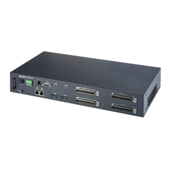
The following figure shows the front panel of the IES-1248-51. Figure 7 IES-1248-51 Front Panel 3.1.1 Front Panel Ports The following table describes the ports on the front panel of the IES-1248-51. Table 1 IES-1248-51 Front Panel Ports CONNECTOR DESCRIPTION CONSOLE Connect this mini-RJ-11 port to a computer for local management. -
Page 50: Front Panel Leds
CO 1-24, 25-48 Connect these Telco-50 connectors to the telephone company for subscribers 1- 24 and 25-48 respectively. 3.1.2 Front Panel LEDs The following table describes the LED indicators on the front panel of the IES-1248-51. Table 2 LED Descriptions COLOR STATUS... -
Page 51: Ethernet Default Settings
Note: For better performance and lower radiation noise, use shielded Ethernet cables. Each 1000/100M port is paired with a mini GBIC slot. The IES-1248-51 uses up to one connection for each pair for a total of two possible gigabit connections (one from each of the two pairs). -
Page 52: Transceiver Installation
3 Insert the fiber-optic cables into the transceiver (you may need to remove cable dust covers). 4 Insert the transceiver into the IES-1248-51’s SFP slot with the exposed section of PCB board facing down. 5 Press the transceiver firmly until it clicks into place. -
Page 53: Transceiver Removal
IES-1248-51 User’s Guide 3.3.2 Transceiver Removal Use the following steps to remove a mini GBIC transceiver (SFP module) from the IES-1248- 1 Remove the fiber-optic cables from the transceiver. 2 Unlock the transceiver’s latch (latch styles vary). 3 Pull the transceiver out of the slot. -
Page 54: Alarm Connections
The IES-1248-51 signals an alarm when it detects an alarm on the ALARM input pins or the IES-1248-51. To signal an alarm, the IES-1248-51 opens the circuit for pins 1 and 6 (the common pin) and closes the circuit for pins 2 and 6. -
Page 55: Chapter 4 Mdf Connections
MDF (see the previous figure). • Some MDFs have surge protection circuitry built in between the two banks; thus, do not connect telephone wires from the telephone company directly to your IES-1248-51. Chapter 4 MDF Connections... -
Page 56: Telco-50 Cables
The internal DSL splitters separate the voice signals from the DSL signals. They feed the DSL signals to the IES-1248-51 and divert the voice signals to the CO Telco-50 connectors. Connect the CO Telco-50 connectors to the PBX or PSTN/ISDN switch. -
Page 57: Mdf Scenarios
MDFs. There is no phone service and you want to install the IES-1248-51 for data-access only. You may connect using an MDF or attach RJ-11 connectors to the non-IES-1248-51 end of the Telco-50 cable and then connect to DSL modems directly. -
Page 58: Procedure To Connect To An Mdf
IES-1248-51 User’s Guide Figure 17 Installation Scenario A 4.6.1.1 Procedure to Connect to an MDF 1 Connect the Telco-50 connector end of the cable to the Telco-50 connector labeled USER. 2 Connect the wiring on the other end of the Telco-50 cable to the upper ports of the MDF using a punch-down tool. -
Page 59: Procedure To Connect To Mdfs
IES-1248-51 User’s Guide • MDF 1 is the original MDF used for telephone connections only. • MDF 2 is used for telephone connections only. • MDF 3 is for DSL service connections. Note: Change the wiring from MDF 1 to MDF 3 for telephone subscribers who want DSL service. -
Page 60: Installation Scenario C
IES-1248-51 User’s Guide 9 Change the wiring from MDF 1 to MDF 3 for telephone subscribers who want DSL service. 4.6.3 Installation Scenario C Phone service is also available but there are two MDFs; one for end-user telephone line connections and the other one for CO telephone wiring connections (see the following figure). -
Page 61: Procedure To Connect To Mdfs
IES-1248-51 User’s Guide Figure 21 Installation Scenario C 4.6.3.1 Procedure to Connect to MDFs 1 Connect the Telco-50 connector end of the cable you want for DSL service to the Telco- 50 connector labeled USER. 2 Connect the wiring on the other side of the Telco-50 cable to the upper ports of MDF 3 using a punch-down tool. - Page 62 IES-1248-51 User’s Guide Chapter 4 MDF Connections...
-
Page 63: Chapter 5 Power Connections
IES-1248-51 power connections. • Keep the IES-1248-51 power switch in the OFF position until you come to the procedure for turning on the power. • Keep the power supply switch in the OFF position until you come to the procedure for turning on the power. -
Page 64: Procedure To Turn On The Ies-1248-51 Power
IES-1248-51 User’s Guide 5.3 Procedure to Turn on the IES-1248-51 Power 1 Turn on the power supply. 2 Move the IES-1248-51 power switch to the ON position. Chapter 5 Power Connections... -
Page 65: Chapter 6 Fan Maintenance
6.2 Removing and Installing the Fan Module The IES-1248-51 fan module is at the left on the front panel. Perform the following procedure to remove the fan module. 1 Loosen the thumbscrew on the front of the fan module. -
Page 66: Figure 23 Removing The Fan Module
IES-1248-51 User’s Guide Figure 23 Removing the Fan Module Figure 24 Fan Module Removed Chapter 6 Fan Maintenance... -
Page 67: Introducing The Web Configurator
This chapter tells how to access and navigate the web configurator. 7.1 Web Configurator Overview The web configurator allows you to use a web browser to manage the IES-1248-51. 7.2 Screen Privilege Levels There is a high or low privilege level for each screen. -
Page 68: Figure 25 Login
IES-1248-51 User’s Guide Figure 25 Login 2 Type admin in the User Name field and your password (default: 1234) in the Password field. Click OK. The main screen appears. This is the web configurator’s main screen. Figure 26 Home A - Click the menu items to open submenu links, and then click on a submenu link to open the screen in the main window. -
Page 69: Navigation Panel
IES-1248-51 User’s Guide 7.4 Navigation Panel In the navigation panel, click a menu item to reveal a list of submenu links. Click a submenu link to go to the corresponding screen. Table 3 Navigation Panel Submenu Links BASIC SETTING ADVANCED APPLICATION... - Page 70 DHCP Relay Use this screen to configure the DHCP relay settings. 2684 Routed Mode Use this screen to configure the IES-1248-51 to handle 2684 routed mode traffic. Downstream Use this screen to block downstream broadcast packets from being sent to Broadcast specified VLANs on specified ports.
-
Page 71: Changing Your Password
Config Save Config Save Use this screen to save the device’s configuration into the nonvolatile memory (the IES-1248-51’s storage that remains even if the IES-1248-51’s power is turned off). 7.5 Changing Your Password After you log in for the first time, it is recommended you change the default administrator password. -
Page 72: Saving Your Configuration
IES-1248-51’s power is turned off. Click Config Save in the navigation panel to save your configuration to nonvolatile memory. Nonvolatile memory refers to the IES-1248-51’s storage that remains even if the IES-1248- 51’s power is turned off. Note: Use Config Save when you are done with a configuration session. -
Page 73: Figure 29 Logout
IES-1248-51 User’s Guide Figure 29 Logout Chapter 7 Introducing the Web Configurator... - Page 74 IES-1248-51 User’s Guide Chapter 7 Introducing the Web Configurator...
-
Page 75: Initial Configuration
3 Use this screen to change the IP address, subnet mask, and default gateway IP address for your network. Apply the settings. Note: If you change the IP address of the IES-1248-51, after you click Apply IP setting, you have to use the new IP address to log into the web configurator again. -
Page 76: Figure 31 Xdsl Port Setup
A channel that is not the super channel can only forward frames with a single VLAN ID (that is configured on that channel). In this case, the IES-1248-51 drops any frames received from the subscriber that are tagged with another VLAN ID. -
Page 77: Figure 32 Vc Setup
IES-1248-51 User’s Guide Figure 32 VC Setup 7 Select any virtual channel’s Select radio button, and click Delete. The following screen appears. Figure 33 VC Setup, Delete 8 Click OK. The following screen appears. Chapter 8 Initial Configuration... -
Page 78: Figure 34 Select Ports
IES-1248-51 User’s Guide Figure 34 Select Ports 9 Click All, and then click Apply. The VC Setup screen is updated. Figure 35 VC Setup 10Select Super Channel to allow the channel to forward frames belonging to multiple VLAN groups (that are not assigned to other channels). Then, enter the VPI and VCI that you use. -
Page 79: Figure 36 Vc Setup
IES-1248-51 User’s Guide Figure 36 VC Setup 11Select the new channel’s Select radio button. Click Copy, and then click Paste. The following screen appears. The following screen appears. Figure 37 Select Ports 12Click All, and then click Apply. The VC Setup screen is updated. -
Page 80: Figure 38 Vc Setup
IES-1248-51 User’s Guide Figure 38 VC Setup 13Click Config Save, Config Save. The Config Save screen appears. Figure 39 Config Save 14Click Save. The following screen should appear. Figure 40 Config Save, Save Successful You can now use the device (with the other settings set to the defaults) to provide service to ADSL subscribers. -
Page 81: Home And Port Statistics Screens
IES-1248-51 User’s Guide H A P T E R Home and Port Statistics Screens This chapter describes the Home (status) and Port Statistics screens. 9.1 Home Screen The Home screen of the web configurator displays a port statistical summary with links to each port showing statistical details. -
Page 82: Ethernet Port Statistics Screen
IES-1248-51 User’s Guide Table 5 Home (continued) LABEL DESCRIPTION Status This field displays whether the Ethernet port is connected (Up) or not (Down). Port Name This field displays the name of the Ethernet port. Media This field displays the type of media that this Ethernet port is using for a connection (Copper or Fiber). -
Page 83: Figure 42 Port Statistics (Ethernet)
IES-1248-51 User’s Guide Figure 42 Port Statistics (Ethernet) The following table describes the labels in this screen. Table 6 Port Statistics (Ethernet) LABEL DESCRIPTION Return Click this to go back to the Home screen. Port Use this drop-down list box to select a port for which you wish to view statistics. - Page 84 IES-1248-51 User’s Guide Table 6 Port Statistics (Ethernet) (continued) LABEL DESCRIPTION Rx mac pause This field shows the number of valid IEEE 802.3x Pause frames received on this port. Rx fragments This field shows the number of frames received that were less than 64 octets long, and contained an invalid FCS, including non-integral and integral lengths.
-
Page 85: Adsl Port Statistics Screen
IES-1248-51 User’s Guide Table 6 Port Statistics (Ethernet) (continued) LABEL DESCRIPTION packet(128-255) This field shows the number of frames received and transmitted (including bad frames) that were 128 to 255 octets in length (this includes FCS octets but excludes framing bits). -
Page 86: Figure 43 Port Statistics (Adsl)
Tx discard packets This field shows the number of outgoing packets that were dropped on this port. The “Tx discard packets” counter always displays “0” because the IES-1248-51 does not discard packets that it sends. Chapter 9 Home and Port Statistics Screens... - Page 87 • The packet filter is enabled and the packets matched a packet filter. • The MAC filter is enabled and the IES-1248-51 dropped the packets according to the MAC filter’s configuration. • The packets contained frames with an invalid VLAN ID.
- Page 88 IES-1248-51 User’s Guide Chapter 9 Home and Port Statistics Screens...
-
Page 89: Chapter 10 System Information
IES-1248-51 User’s Guide H A P T E R System Information The System Information screen displays general device information (such as firmware version number) and hardware polling information (such as fan status). You can check the firmware version number and monitor the hardware status in this screen. -
Page 90: Figure 44 System Info
IES-1248-51 User’s Guide Figure 44 System Info Chapter 10 System Information... -
Page 91: Table 8 System Info
IES-1248-51 User’s Guide The following table describes the labels in this screen. Table 8 System Info LABEL DESCRIPTION System Name This field displays the device 's model name. ZyNOS F/W Version This field displays the version number of the device 's current firmware including the date created. - Page 92 Click Apply to save the name changes to the IES-1248-51’s volatile memory. The IES-1248-51 loses these changes if it is turned off or loses power, so use the Config Save link on the navigation panel to save your changes to the non- volatile memory when you are done configuring.
-
Page 93: Chapter 11 General Setup
IES-1248-51 User’s Guide H A P T E R General Setup The General Setup screen allows you to configure general device identification information. It also allows you to set the system time manually or get the current time and date from an external server when you turn on your device. -
Page 94: Table 9 General Setup
Click Apply to save your changes to the IES-1248-51’s volatile memory. The IES-1248-51 loses these changes if it is turned off or loses power, so use the Config Save link on the navigation panel to save your changes to the non- volatile memory when you are done configuring. -
Page 95: Chapter 12 User Account
User Account The User Account screens allows you to set up and configure system administrator accounts for the IES-1248-51. You can also configure the authentication policy for IES-1248-51 administrators. This is different than port authentication in Chapter 25 on page 171. -
Page 96: Authentication Screen
Select low to allow the administrator to use only low privilege commands. Low privilege commands are read only. Click Add to save your changes to the IES-1248-51’s volatile memory. The IES- 1248-51 loses these changes if it is turned off or loses power, so use the Config Save link on the navigation panel to save your changes to the non-volatile memory when you are done configuring. -
Page 97: Table 11 User Account
There is a high, medium or low privilege level for each command. You can also choose to deny access to the IES-1248-51. Select high to allow the administrator to use all commands including the lower privilege commands. - Page 98 IES-1248-51 User’s Guide Chapter 12 User Account...
-
Page 99: Chapter 13 Switch Setup
(see Figure 48 on page 100 for an example). If you have multiple IES-1248-51 connected on the same network and set to standalone mode, they do not all need to have the same port isolation setting. Chapter 13 Switch Setup... -
Page 100: Port Isolation With Standalone Switch Mode Example
13.2.2 Port Isolation with Standalone Switch Mode Example The following graphic shows IES-1248-51 1 and 2 connected to each other and the Ethernet backbone switch (3) in a network topology that creates a loop. The IES-1248-51 are using the standalone switch mode and have RSTP enabled. -
Page 101: Port Isolation With Daisychain Switch Mode Example
IES-1248-51 User’s Guide 13.2.4 Port Isolation with Daisychain Switch Mode Example In the example below, the IES-1248-51 1 has its Ethernet port one (ENET 1) connected to the Ethernet backbone switch (3) and it’s Ethernet port two (ENET2) connected to Ethernet port one (ENET 1) of the daisychained IES-1248-51 (2). -
Page 102: Figure 50 Switch Setup
IES-1248-51 User’s Guide Figure 50 Switch Setup The following table describes the labels in this screen. Table 12 Switch Setup LABEL DESCRIPTION MAC Address Enter a time from 10 to 10,000 seconds. This is how long all dynamically learned Learning MAC addresses remain in the MAC address table before they age out (and must be relearned). - Page 103 Click Apply to save your changes to the IES-1248-51’s volatile memory. The IES-1248-51 loses these changes if it is turned off or loses power, so use the Config Save link on the navigation panel to save your changes to the non- volatile memory when you are done configuring.
- Page 104 IES-1248-51 User’s Guide Chapter 13 Switch Setup...
-
Page 105: Chapter 14 Ip Setup
The following table describes the labels in this screen. Table 13 IP Setup LABEL DESCRIPTION Enter the IP address of your IES-1248-51 in dotted decimal notation for example 1.2.3.4. IP Mask Enter the IP subnet mask of your IES-1248-51 in dotted decimal notation for example 255.255.255.0. - Page 106 IES-1248-51 User’s Guide Chapter 14 IP Setup...
-
Page 107: Chapter 15 Enet Port Setup
IES-1248-51 determines the connection speed by detecting the signal on the cable and using full duplex. When an Ethernet port is set to Auto, the IES-1248-51 tries to make a fiber connection first and does not attempt to use the RJ-45 port if the fiber connection is successful. - Page 108 Click Apply to save your changes to the IES-1248-51’s volatile memory. The IES-1248-51 loses these changes if it is turned off or loses power, so use the Config Save link on the navigation panel to save your changes to the non- volatile memory when you are done configuring.
-
Page 109: Chapter 16 Xdsl Port Setup
16.1 ADSL Standards Overview These are the ADSL standards and rates that the IES-1248-51 supports at the time of writing. The actual transfer rates will vary depending on what the subscriber’s device supports, the line conditions and the connection distance. -
Page 110: Interleave Delay
32 Kbps, and if you specify 66 Kbps, the actual rate will not be over 64Kbps. Regardless of a profile’s configured upstream and downstream rates, the IES-1248-51 automatically limits the actual rates for each individual port to the maximum speeds supported by the port’s ADSL operational mode. -
Page 111: Default Settings
IES-1248-51 User’s Guide 16.6 Default Settings The default profile always exists and all of the ADSL ports use the default profile settings when the IES-1248-51 is shipped. The default profile's name is set to DEFVAL_MAX Appendix A on page 371 for the settings of the default profile and ADSL port default settings. -
Page 112: Figure 54 Select Ports
IES-1248-51 User’s Guide Table 16 xDSL Port Setup (continued) LABEL DESCRIPTION Copy Port Do the following to copy settings from one DSL port to another DSL port or ports. Paste 1. Select the number of the DSL port from which you want to copy settings. -
Page 113: Xdsl Port Setting Screen
IES-1248-51 User’s Guide Table 16 xDSL Port Setup (continued) LABEL DESCRIPTION Packet Filter Select this check box to copy this port’s packet filter settings. These are configured in the Packet Filtering screen (see Chapter 22 on page 161). Paste See Copy Port. -
Page 114: Figure 55 Xdsl Port Setting
127). Mode Select the port’s ADSL operational mode. Select the mode that the subscriber’s device uses or auto to have the IES-1248-51 automatically determine the mode to use. See Table 15 on page 109 for information on the individual ADSL modes. - Page 115 Alarm Profile Select the port’s alarm profile. The alarm profile defines alarm thresholds for the ADSL port. The IES-1248-51 sends an alarm trap and generates a syslog entry when the thresholds of the alarm profile are exceeded (see Section 17.6 on page 135).
- Page 116 IES-1248-51 User’s Guide Table 17 xDSL Port Setting (continued) LABEL DESCRIPTION L2 ATPR Set the maximum Aggregate Transmit Power Reduction (ATPR) in decibels (dB) that is permitted in a L2 power reduction. The system can gradually decrease the ADSL line transmission power while it is in the L2 power mode. This is the largest individual power reduction allowed in the L2 power mode.
-
Page 117: Virtual Channels
For example, you want to give high priority to voice service on one of the ADSL ports. Use the Edit Static VLAN screen to configure a static VLAN on the IES-1248-51 for voice on the port. -
Page 118: Llc
You can also change an individual virtual channel by assigning it a different profile. The IES-1248-51 provides two default virtual channel profiles: DEFVAL (for LLC encapsulation) and DEFVAL_VC (for VC encapsulation). By default, all virtual channels are associated to DEFVAL. -
Page 119: Figure 56 Vc Setup
This field is read-only once you click on a port number below. Super Channel The IES-1248-51 forwards frames belonging to VLAN groups that are not assigned to specific channels to the super channel. Enable the super channel option to have this channel forward frames belonging to multiple VLAN groups (that are not assigned to other channels). - Page 120 US VC Profile Use the drop-down list box to select a VC profile to use for this channel’s upstream traffic. The IES-1248-51 does not perform upstream traffic policing if you do not specify an upstream VC profile. Note: Upstream traffic policing should be used in conjunction with the ATM shaping feature on the subscriber’s device.
-
Page 121: Figure 57 Basic Setting, Xdsl Port Setup, Vc Setup, Delete
IES-1248-51 User’s Guide Table 18 VC Setup (continued) LABEL DESCRIPTION Select Do the following to remove one or more PVCs. Delete 1. Select a PVC’s Select radio button. 2. Click Delete. 3. Click OK if you want to remove the PVC from other ports. Click Cancel to only remove the one you selected. -
Page 122: Priority-Based Pvcs
A PPVC (Priority-based PVC) allows you to give different priorities to PVCs that are members of the same VLAN. The IES-1248-51 uses eight priority queues (also called levels) for the member PVCs. The system maps frames with certain IEEE 802.1p priorities to a PVC with a particular priority queue. -
Page 123: Ppvc Setup Screen
Clicking Add / Modify saves your changes to the IES-1248-51’s volatile memory. The IES-1248-51 loses these changes if it is turned off or loses power, so use the Config Save link on the navigation panel to save your changes to the non- volatile memory when you are done configuring. -
Page 124: Ppvc Setup Members Screen
Clicking Delete saves your changes to the IES-1248-51’s volatile memory. The IES-1248-51 loses these changes if it is turned off or loses power, so use the Config Save link on the navigation panel to save your changes to the non- volatile memory when you are done configuring. -
Page 125: Table 21 Ppvc Setup, Edit
Clicking Delete saves your changes to the IES-1248-51’s volatile memory. The IES-1248-51 loses these changes if it is turned off or loses power, so use the Config Save link on the navigation panel to save your changes to the non- volatile memory when you are done configuring. - Page 126 IES-1248-51 User’s Guide Chapter 16 xDSL Port Setup...
-
Page 127: Chapter 17 Xdsl Profiles Setup
IES-1248-51 User’s Guide H A P T E R xDSL Profiles Setup A profile is a list of settings that you define. Then you can assign them to one or more individual ports. For background information about many of these settings, see... -
Page 128: Table 22 Port Profile
IES-1248-51 User’s Guide The following table describes the labels in this screen. Table 22 Port Profile LABEL DESCRIPTION VC Profile Click VC Profile to open the VC Profile screen where you can configure virtual channel profiles (see Section 17.5 on page 133). - Page 129 Click Add to save your changes to the IES-1248-51’s volatile memory. The IES- 1248-51 loses these changes if it is turned off or loses power, so use the Config Save link on the navigation panel to save your changes to the non-volatile memory when you are done configuring.
-
Page 130: Atm Qos
IES-1248-51 User’s Guide 17.2 ATM QoS ATM Quality of Service (QoS) mechanisms provide the best service on a per-flow guarantee. ATM network infrastructure was designed to provide QoS. It uses fixed cell sizes and built-in traffic management (see Section 17.3 on page 130). -
Page 131: Unspecified Bit Rate (Ubr)
IES-1248-51 User’s Guide 17.3.1.3 Unspecified Bit Rate (UBR) The Unspecified Bit Rate (UBR) ATM traffic class is similar to the ABR traffic class for bursty data transfers. However, while ABR gives subscribers a set amount of bandwidth, UBR doesn’t guarantee any bandwidth and only delivers traffic when the network has spare bandwidth. -
Page 132: Cell Delay Variation Tolerance (Cdvt)
IES-1248-51 User’s Guide Figure 63 PCR, SCR and MBS in Traffic Shaping 17.3.2.4 Cell Delay Variation Tolerance (CDVT) Cell Delay Variation Tolerance (CDVT) is the accepted tolerance of the difference between a cell’s transfer delay and the expected transfer delay. CDVT controls the time scale over which the PCR is enforced. -
Page 133: Upstream Policing
The upstream policing feature can be enabled/disabled per PVC. No matter which ATM traffic class is used for the PVC's upstream traffic (CBR, VBR, or UBR), the IES-1248-51 will drop any upstream traffic that violates the specified ATM VC profile. -
Page 134: Figure 65 Vc Profile
IES-1248-51 User’s Guide Figure 65 VC Profile The following table describes the labels in this screen. Table 23 VC Profile LABEL DESCRIPTION Port Profile Click Port Profile to configure port profiles and assign them to individual ports (see Section 17.1 on page 127). -
Page 135: Alarm Profile Screen
Click Cancel to start configuring the screen again. 17.6 Alarm Profile Screen Alarm profiles define ADSL port alarm thresholds. The IES-1248-51 sends an alarm trap and generates a syslog entry when the thresholds of the alarm profile are exceeded. To open this screen, click Basic Setting, xDSL Profiles Setup, Alarm Profile. -
Page 136: Figure 66 Alarm Profile
DEFVAL profile). You can use up to 31 ASCII characters; spaces are not allowed. Click Add to save your changes to the IES-1248-51’s volatile memory. The IES- 1248-51 loses these changes if it is turned off or loses power, so use the Config Save link on the navigation panel to save your changes to the non-volatile memory when you are done configuring. -
Page 137: Igmp Filtering
LABEL DESCRIPTION ATU-R These fields are for traffic going from the IES-1248-51 to the subscriber’s device. 15 Min LOF This field sets the limit for the number of seconds a Loss Of Frame is permitted to occur within 15 minutes. -
Page 138: Igmp Filter Profile Screen
IES-1248-51 User’s Guide 17.8 IGMP Filter Profile Screen You can use the IGMP filter profiles to control access to a service that uses a specific multicast group (like a SIP server for example). Configure an IGMP filter profile that allows access to that multicast group. -
Page 139: Table 25 Igmp Filter Profile
If you want to add a single multicast IP address, enter it in both the Start IP and End IP fields. Click Add to save your changes to the IES-1248-51’s volatile memory. The IES- 1248-51 loses these changes if it is turned off or loses power, so use the Config Save link on the navigation panel to save your changes to the non-volatile memory when you are done configuring. - Page 140 IES-1248-51 User’s Guide Chapter 17 xDSL Profiles Setup...
-
Page 141: Chapter 18 Xdsl Line Data
IES-1248-51 User’s Guide H A P T E R xDSL Line Data 18.1 xDSL Line Rate Info Screen This screen displays an ADSL port’s line operating values. Information obtained prior to training to steady state transition will not be valid or will be old information. -
Page 142: Xdsl Performance Screen
The vendor ID, vendor version number and product serial number are obtained from vendor ID fields (see ITU-T G.994.1) or R-MSGS1 (see T1.413). At the time of writing, the IES-1248-51 always uses Trellis coding. 18.2 xDSL Performance Screen These counters display line performance data that has been accumulated since the system started. -
Page 143: Figure 69 Xdsl Performance
IES-1248-51 User’s Guide To open this screen, click Basic Setting, xDSL Line Data, Line Performance. Figure 69 xDSL Performance The following table describes the labels in this screen. Table 27 xDSL Performance LABEL DESCRIPTION Line Rate Click Line Rate to display an ADSL port’s line operating values (see Section 18.1 on page... -
Page 144: Xdsl Line Data Screen
IES-1248-51 User’s Guide Table 27 xDSL Performance (continued) LABEL DESCRIPTION ATUC/ATUR ES The Number of Errored Seconds transmitted (downstream) or received (upstream) on this ADSL port. ATUC/ATUR SES The Number of Severely Errored Seconds transmitted (downstream) or received (upstream) on this ADSL port. Severely errored seconds contained 30% or more errored blocks or at least one defect. - Page 145 IES-1248-51 User’s Guide Discrete Multi-Tone (DMT) modulation divides up a line’s bandwidth into tones. This screen displays the number of bits transmitted for each tone. This can be used to determine the quality of the connection, whether a given sub-carrier loop has sufficient margins to support ADSL transmission rates, and possibly to determine whether certain specific types of interference or line attenuation exist.
-
Page 146: Table 28 Xdsl Line Data
Bit Allocation “DS carrier load” displays the number of bits transmitted per DMT tone for the downstream channel (from the IES-1248-51 to the subscriber’s DSL modem or router). “US carrier load” displays the number of bits received per DMT tone for the upstream channel (from the subscriber’s DSL modem or router to the IES-1248-... -
Page 147: Chapter 19 Vlan
IES-1248-51 User’s Guide H A P T E R VLAN This chapter shows you how to configure IEEE 802.1Q tagged VLANs. 19.1 Introduction to VLANs A VLAN (Virtual Local Area Network) allows a physical network to be partitioned into multiple logical networks. Devices on a logical network belong to one group. A device can belong to more than one group. -
Page 148: Forwarding Tagged And Untagged Frames
3 Bits 1 Bit 12 bits The IES-1248-51 handles up to 4094 VLANs (VIDs 1-4094). The device accepts incoming frames with VIDs 1-4094. 19.2.1 Forwarding Tagged and Untagged Frames Each port on the device is capable of passing tagged or untagged frames. To forward a frame from an 802.1Q VLAN-aware switch to an 802.1Q VLAN-unaware switch, the IES-1248-51... -
Page 149: Figure 71 Vlan Status
Section 19.5 on page 151. The Number of This is the number of VLANs configured on the IES-1248-51. VLAN Page X of X This identifies which page of VLAN status information is displayed and how many total pages of VLAN status information there are. -
Page 150: Static Vlan Setting Screen
This field shows how long it has been since a normal VLAN was registered or a static VLAN was set up. Status This field shows that this VLAN was added to the IES-1248-51 statically, that is, added as a permanent entry. Poll Interval(s) The text box displays how often (in seconds) this screen refreshes. -
Page 151: Vlan Port Setting Screen
Clicking Add saves your changes to the IES-1248-51’s volatile memory. The IES-1248-51 loses these changes if it is turned off or loses power, so use the Config Save link on the navigation panel to save your changes to the non- volatile memory when you are done configuring. -
Page 152: Figure 73 Vlan Port Setting
Click Apply to save your changes to the IES-1248-51’s volatile memory. The IES-1248-51 loses these changes if it is turned off or loses power, so use the Config Save link on the navigation panel to save your changes to the non- volatile memory when you are done configuring. -
Page 153: Figure 74 Select Ports
4. Click Apply to paste the settings. Figure 74 Select Ports At the time of writing, the VLAN Acceptable Frame Type field is read-only for the Ethernet ports. The IES-1248-51 accepts both tagged and untagged incoming frames on the Ethernet ports. Chapter 19 VLAN... - Page 154 IES-1248-51 User’s Guide Chapter 19 VLAN...
-
Page 155: Chapter 20 Igmp
IGMP snooping or that you have manually configured) to ports that are members of that group. The IES-1248-51 discards multicast traffic destined for multicast groups that it does not know. IGMP snooping generates no additional network traffic, allowing you to significantly reduce multicast traffic passing through your device. -
Page 156: Igmp Status Screen
There should only be one upstream interface (also known as the query port) for one query VLAN on the IES-1248-51. A downstream interface is a port that connects to a host (such as a computer). -
Page 157: Igmp Setup Screen
This is the total number of Report packets received. Leave This is the total number of Leave packets received. Number of IGMP This is how many IGMP groups the IES-1248-51 has identified on the local Groups network. Previous Click one of these buttons to show the previous/next screen if all of the information cannot be seen in one screen. -
Page 158: Igmp Filter Setup Screen
Clicking Apply saves your changes to the IES-1248-51’s volatile memory. The IES-1248-51 loses these changes if it is turned off or loses power, so use the Config Save link on the navigation panel to save your changes to the non- volatile memory when you are done configuring. -
Page 159: Chapter 21 Static Multicast
Table 34 Static Multicast LABEL DESCRIPTION The Number of This is the number of static multicast entries configured on the IES-1248-51. Static Multicast Page X of X This identifies which page of information is displayed and the total number of pages of information. - Page 160 Clicking Add saves your changes to the IES-1248-51’s volatile memory. The IES-1248-51 loses these changes if it is turned off or loses power, so use the Config Save link on the navigation panel to save your changes to the non- volatile memory when you are done configuring.
-
Page 161: Chapter 22 Filtering
Filtering This chapter describes how to configure the Packet Filter screen. 22.1 Packet Filter Screen Use this screen to set which types of packets the IES-1248-51 accepts on individual ADSL ports. To open this screen, click Advanced Application, Filtering. Figure 79 Packet Filter The following table describes the labels in this screen. - Page 162 These are the packet filter settings for each port. NetBios, DHCP, “V” displays for the packet types that the IES-1248-51 is to accept on the port. “- EAPOL, IGMP, “ displays for packet types that the IES-1248-51 is to reject on the port (packet PPPoE Only types that are not listed are accepted).
-
Page 163: Chapter 23 Mac Filter
IES-1248-51 User’s Guide H A P T E R MAC Filter This chapter introduces the MAC filter. 23.1 MAC Filter Introduction Use the MAC filter to control from which MAC (Media Access Control) addresses frames can (or cannot) come in through a port. -
Page 164: Table 36 Mac Filter
Click Apply to save your changes to the IES-1248-51’s volatile memory. The IES-1248-51 loses these changes if it is turned off or loses power, so use the Config Save link on the navigation panel to save your changes to the non- volatile memory when you are done configuring. -
Page 165: Spanning Tree Protocol
(RSTP). 24.1 RSTP and STP RSTP adds rapid reconfiguration capability to STP. The IES-1248-51 supports RSTP and the earlier STP. RSTP and STP detect and break network loops and provide backup links between switches, bridges or routers. They allow a device to interact with other RSTP or STP-aware devices in your network to ensure that only one path exists between any two stations on the network. -
Page 166: Figure 81 Stp Root Ports And Designated Ports
IES-1248-51 User’s Guide After a bridge determines the lowest cost-spanning tree with RSTP, it enables the root port and the ports that are the designated ports for the connected LANs, and disables all other ports that participate in RSTP. Network packets are therefore only forwarded between enabled ports, eliminating any possible network loops. -
Page 167: Spanning Tree Protocol Status Screen
IES-1248-51 User’s Guide Table 38 RSTP Port States (continued) RSTP PORT STATE STP PORT STATE DESCRIPTION Discarding Listening In RSTP, BPDUs are discarded. In STP, all BPDUs are received and processed. Learning Learning All BPDUs are received and processed. Information frames are submitted to the learning process but not forwarded. -
Page 168: Table 39 Spanning Tree Protocol Status
Designated root ID This is the unique identifier for the root bridge, consisting of bridge priority plus MAC address. This ID is the same in Our bridge ID if the IES-1248-51 is the root switch. Topology change This is the number of times the spanning tree has been reconfigured. -
Page 169: Spanning Tree Protocol Screen
The following table describes the labels in this screen. Table 40 Spanning Tree Protocol LABEL DESCRIPTION STP Status Click STP Status to display the IES-1248-51’s STP status (see Section 24.2 on page 167). Active Select this check box to turn on RSTP. - Page 170 Click Apply to save your changes to the IES-1248-51’s volatile memory. The IES-1248-51 loses these changes if it is turned off or loses power, so use the Config Save link on the navigation panel to save your changes to the non- volatile memory when you are done configuring.
-
Page 171: Chapter 25 Port Authentication
Figure 84 RADIUS Server 25.1.2 Introduction to Local User Database By storing user profiles locally on the IES-1248-51, your IES-1248-51 is able to authenticate users without interacting At the time of writing, Windows XP of the Microsoft operating systems supports 802.1x. See the Microsoft web site for information on other Windows operating system support. -
Page 172: Radius Screen
Click Apply to save your changes to the IES-1248-51’s volatile memory. The IES-1248-51 loses these changes if it is turned off or loses power, so use the Config Save link on the navigation panel to save your changes to the non- volatile memory when you are done configuring. -
Page 173: Screen
Type the password again to make sure you have entered it properly. confirm Click Add to save your changes to the IES-1248-51’s volatile memory. The IES- 1248-51 loses these changes if it is turned off or loses power, so use the Config Save link on the navigation panel to save your changes to the non-volatile memory when you are done configuring. -
Page 174: Table 42 802.1X
Click Apply to save your changes to the IES-1248-51’s volatile memory. The IES-1248-51 loses these changes if it is turned off or loses power, so use the Config Save link on the navigation panel to save your changes to the non- volatile memory when you are done configuring. -
Page 175: Chapter 26 Port Security
Clear this check box to not limit the number of MAC addresses that can be learned on the port. Limited Number of Specify how many MAC addresses the IES-1248-51 can learn on this port. The Learned MAC range is 1~128. -
Page 176: Figure 88 Select Ports
Click Apply to save your changes to the IES-1248-51’s volatile memory. The IES-1248-51 loses these changes if it is turned off or loses power, so use the Config Save link on the navigation panel to save your changes to the non- volatile memory when you are done configuring. -
Page 177: Chapter 27 Dhcp Relay
DHCP servers for each VLAN. 27.2 DHCP Relay Agent Information Option (Option 82) The IES-1248-51 can add information to DHCP requests that it relays to a DHCP server. This helps provide authentication about the source of the requests. You can also specify additional information for the IES-1248-51 to add to the DHCP requests that it relays to the DHCP server. -
Page 178: Dhcp Relay Screen
IES-1248-51 User’s Guide The Agent Information field that the IES-1248-51 adds also contains an “Agent Remote-ID sub-option” of information that you specify. The following figure shows the format of the Agent Remote ID sub-option. The 2 in the first field identifies this as an Agent Remote ID sub-option. The length N gives the total number of octets in the Agent Information Field. -
Page 179: Table 44 Dhcp Relay
Table 44 DHCP Relay LABEL DESCRIPTION Enable DHCP Relay: Enable DHCP relay to have the IES-1248-51 relay DHCP requests to a DHCP server and the server’s responses back to the clients. Relay Mode Specify how the IES-1248-51 relays DHCP requests. - Page 180 IES-1248-51 User’s Guide Table 44 DHCP Relay (continued) LABEL DESCRIPTION Secondary Server IP This field displays the IP address of a second DHCP server to which the switch should relay DHCP requests. This field is 0.0.0.0 if the primary server is the only DHCP relay.
-
Page 181: 2684 Routed Mode
192.168.10.102 and is in VLAN 1. The IES-1248-51 uses IP address 192.168.10.101. The subscriber’s device (the CPE) is connected to DSL port 1 on the IES-1248-51 and the 2684 routed mode traffic is to use the PVC identified by VPI 8 and VCI 35. The CPE device’s WAN IP address is 192.168.10.200. -
Page 182: 2684 Routed Pvc Screen
WAN IP address or routed gateway IP address. • The IES-1248-51’s management IP address should not be in the same subnet as the one defined by the WAN IP address and netmask of the subscriber’s device. It is suggested that you set the netmask of the subscriber’s WAN IP address to 32 to avoid this problem. -
Page 183: Figure 93 2684 Routed Pvc
Click Add to save your changes to the IES-1248-51’s volatile memory. The IES-1248-51 loses these changes if it is turned off or loses power, so use the Config Save link on the navigation panel to save your changes to the non- volatile memory when you are done configuring. -
Page 184: 2684 Routed Domain Screen
Clicking Delete saves your changes to the IES-1248-51’s volatile memory. The IES-1248-51 loses these changes if it is turned off or loses power, so use the Config Save link on the navigation panel to save your changes to the non- volatile memory when you are done configuring. -
Page 185: Table 46 2684 Routed Domain
Click Add to save your changes to the IES-1248-51’s volatile memory. The IES-1248-51 loses these changes if it is turned off or loses power, so use the Config Save link on the navigation panel to save your changes to the non- volatile memory when you are done configuring. -
Page 186: Rpvc Arp Proxy Screen
Click Apply Setting to save your changes to the IES-1248-51’s volatile memory. The IES-1248-51 loses these changes if it is turned off or loses power, so use the Config Save link on the navigation panel to save your changes to the non- volatile memory when you are done configuring. -
Page 187: Figure 96 2684 Routed Gateway
Click Add to save your changes to the IES-1248-51’s volatile memory. The IES-1248-51 loses these changes if it is turned off or loses power, so use the Config Save link on the navigation panel to save your changes to the non- volatile memory when you are done configuring. - Page 188 IES-1248-51 User’s Guide Chapter 28 2684 Routed Mode...
-
Page 189: Chapter 29 Downstream Broadcast
Click Add to save your changes to the IES-1248-51’s volatile memory. The IES-1248-51 loses these changes if it is turned off or loses power, so use the Config Save link on the navigation panel to save your changes to the non- volatile memory when you are done configuring. - Page 190 Clicking Delete saves your changes to the IES-1248-51’s volatile memory. The IES-1248-51 loses these changes if it is turned off or loses power, so use the Config Save link on the navigation panel to save your changes to the non- volatile memory when you are done configuring.
-
Page 191: Chapter 30 Syslog
Click Apply to save your changes to the IES-1248-51’s volatile memory. The IES-1248-51 loses these changes if it is turned off or loses power, so use the Config Save link on the navigation panel to save your changes to the non- volatile memory when you are done configuring. - Page 192 IES-1248-51 User’s Guide Chapter 30 Syslog...
-
Page 193: Chapter 31 Access Control
Simple Network Management Protocol is a protocol used for exchanging management information between network devices. SNMP is a member of TCP/IP protocol suite. A manager station can manage and monitor the IES-1248-51 through the network via SNMP version one (SNMPv1) and/or SNMP version 2c. The next figure illustrates an SNMP management operation. -
Page 194: Figure 100 Snmp Management Model
IES-1248-51 User’s Guide Figure 100 SNMP Management Model An SNMP managed network consists of two main components: agents and a manager. An agent is a management software module that resides in a managed device (the IES-1248- 51). An agent translates the local management information from the managed device into a form compatible with SNMP. -
Page 195: Supported Mibs
• ies1248.mib 31.3.2 SNMP Traps The IES-1248-51 can send the following SNMP traps to an SNMP manager when an event occurs. ATUC refers to the downstream channel (for traffic going from the IES-1248-51 to the subscriber). ATUR refers to the upstream channel (for traffic coming from the subscriber to the IES-1248-51). - Page 196 IES-1248-51 User’s Guide Table 53 SNMPv2 Traps (continued) TRAP NAME DESCRIPTION overheatOver This trap is sent when the system is no longer overheated. The variable is the current system temperature in Celsius. fanRpmLow This trap is sent when the RPM of the fan is too low. The variable is the current RPM of the fan.
-
Page 197: Snmp Screen
IES-1248-51 User’s Guide Table 53 SNMPv2 Traps (continued) TRAP NAME DESCRIPTION adslAturPerfLossThreshTrap The number of times a Loss Of Signal has occurred within 15 minutes for the ATUR has reached the threshold. currValue is the number of times a Loss Of Signal has occurred within the 15-minute interval. -
Page 198: Service Access Control Screen
Click Apply to save your changes to the IES-1248-51’s volatile memory. The IES-1248-51 loses these changes if it is turned off or loses power, so use the Config Save link on the navigation panel to save your changes to the non- volatile memory when you are done configuring. -
Page 199: Remote Management Screen
Click Apply to save your changes to the IES-1248-51’s volatile memory. The IES-1248-51 loses these changes if it is turned off or loses power, so use the Config Save link on the navigation panel to save your changes to the non- volatile memory when you are done configuring. - Page 200 Click Apply to save your changes to the IES-1248-51’s volatile memory. The IES-1248-51 loses these changes if it is turned off or loses power, so use the Config Save link on the navigation panel to save your changes to the non- volatile memory when you are done configuring.
-
Page 201: Chapter 32 Static Routing
Static Routing This chapter shows you how to configure the static routing function. Static routes tell the IES-1248-51 how to forward the IES-1248-51’s own IP traffic when you configure the TCP/IP parameters manually. This is generally useful for allowing management of the device from a device with an IP address on a different subnet from that of the device’s... -
Page 202: Table 57 Static Routing
Cancel Click Cancel to reset the fields to your previous configuration. Use this section to look at a summary of all static routes in the IES-1248-51. Previous Page Click this to display the preceding page of static route entries. -
Page 203: Chapter 33 Alarm
33.1 Alarm The IES-1248-51 monitors for equipment, DSL and system alarms and can report them via SNMP or syslog. You can specify the severity level of an alarm(s) and where the system is to send the alarm(s). -
Page 204: Alarm Descriptions
33.3 Alarm Descriptions This table describes alarms that the system can send. ATUC refers to the downstream channel (for traffic going from the IES-1248-51 to the subscriber). ATUR refers to the upstream channel (for traffic coming from the subscriber to the IES-1248-51). - Page 205 IES-1248-51 User’s Guide Table 59 Alarm Descriptions (continued) ALARM CONDITION SEVERITY CLEARABLE DESCRIPTION The number of times a Loss Of (5005)ad_perf_lop_thresh info Power has occurred within 15 minutes for the ATU (C or R) has reached the threshold. The number of error seconds within...
-
Page 206: Alarm Event Setup Screen
IES-1248-51 User’s Guide Table 59 Alarm Descriptions (continued) ALARM CONDITION SEVERITY CLEARABLE DESCRIPTION A Gigabit Ethernet interface is up. enet (20000)up info A Gigabit Ethernet interface is down. enet (20001)down major 33.4 Alarm Event Setup Screen This screen lists the alarms that the system can generate along with the severity levels of the alarms and where the system is to send them. -
Page 207: Edit Alarm Event Setup Screen
IES-1248-51 User’s Guide The following table describes the labels in this screen. Table 60 Alarm Event Setup LABEL DESCRIPTION Alarm Status Click Alarm Status to go to a screen that displays the alarms that are currently in the system (see Section 33.2 on page... -
Page 208: Alarm Port Setup Screen
Click Apply to save your changes to the IES-1248-51’s volatile memory. The IES-1248-51 loses these changes if it is turned off or loses power, so use the Config Save link on the navigation panel to save your changes to the non- volatile memory when you are done configuring. -
Page 209: Figure 108 Alarm Port Setup
Click Apply to save your changes to the IES-1248-51’s volatile memory. The IES-1248-51 loses these changes if it is turned off or loses power, so use the Config Save link on the navigation panel to save your changes to the non- volatile memory when you are done configuring. - Page 210 IES-1248-51 User’s Guide Chapter 33 Alarm...
-
Page 211: Chapter 34 Maintenance
IES-1248-51 User’s Guide H A P T E R Maintenance This chapter explains how to use the maintenance screens. 34.1 Maintenance Screen To open this screen, click Management, Maintenance. Figure 109 Maintenance 34.2 Firmware Upgrade Screen Use this screen to upgrade your device firmware. See the System Info screen to verify your current firmware version number. -
Page 212: Restore Configuration Screen
IES-1248-51 User’s Guide Type the path and file name of the firmware file you wish to upload to the device in the File Path text box or click Browse to locate it. After you have specified the file, click Upgrade. -
Page 213: Load Factory Defaults
IES-1248-51 User’s Guide Note: You can change the “.dat” file to a “.txt” file and still upload it back to the IES- 1248-51. 34.5 Load Factory Defaults Use this function to clear all device configuration information you configured and return to the factory defaults. -
Page 214: Command Line Ftp
IES-1248-51 User’s Guide Figure 114 Reboot System Click OK. You then see the screen as shown in Figure 113 on page 213. Click OK again and wait for the device to restart. This takes up to two minutes. This does not affect the device’s configuration. -
Page 215: Chapter 35 Diagnostic
IES-1248-51 User’s Guide H A P T E R Diagnostic This chapter explains the Diagnostic screens. 35.1 Diagnostic Screen Use this screen to check system logs, ping IP addresses or perform loopback tests. To open this screen, click Management, Diagnostic. -
Page 216: Table 63 Diagnostic
Select a port number from the Port drop-down list box and click Set LDM Port to have the IES-1248-51 perform line diagnostics on the specified port. The ADSL port must be set to ADSL2 or ADSL2+ ADSL operational mode and have a connection. -
Page 217: Log Format
IES-1248-51 User’s Guide Table 63 Diagnostic (continued) LABEL DESCRIPTION Select a port number from the Port drop-down list box and a power management mode from the Mode drop-down list box and click Set PMM Mode to have the specified port use the specified power management mode. -
Page 218: Log Messages
Someone attempted to upload a firmware file with a wrong Received Firmware WARN identity via FTP. Invalid! A file was uploaded to the IES-1248-51 by FTP. Received File <file>! INFO <file> - received file’s name The temperature was too high at one of the temperature... -
Page 219: Ldm Test Parameters
DMT sub-carrier’s SNR is the ratio between the received signal power and the received noise power. The signal-to-noise ratio margin is the maximum that the received noise power could increase with the IES-1248-51 still being able to meet its transmission targets. -
Page 220: Tonediag Parameters
DMT sub-carrier’s SNR is the ratio between the received signal power and the received noise power. The signal-to-noise ratio margin is the maximum that the received noise power could increase with the IES-1248-51 still being able to meet its transmission targets. -
Page 221: Chapter 36 Mac Table
This chapter introduces the MAC Table. 36.1 Introduction to MAC Table The MAC table lists device MAC addresses that are dynamically learned by the IES-1248-51. The table shows the following for each MAC address: the port upon which Ethernet frames were received from the device, to which VLAN groups the device belongs (if any) and to which channel it is connected (for devices connected to DSL ports). -
Page 222: Mac Table Screen
IES-1248-51 User’s Guide • If the device has already learned the port for this MAC address, but the destination port is the same as the port it came in on, then it filters the frame. 36.2 MAC Table Screen To open this screen, click Management, MAC Table. -
Page 223: Chapter 37 Arp Table
IES-1248-51 User’s Guide H A P T E R ARP Table This chapter describes the ARP Table. 37.1 Introduction to ARP Table Address Resolution Protocol (ARP) is a protocol for mapping an Internet Protocol address (IP address) to a physical machine address, also known as a Media Access Control or MAC address, on the local area network. -
Page 224: Figure 118 Arp Table
IES-1248-51 User’s Guide Figure 118 ARP Table The following table describes the labels in this screen. Table 69 ARP Table LABEL DESCRIPTION Flush Click Flush to remove all of the entries from the ARP table. Total X ARP Entries This displays the number of entries in the ARP table. -
Page 225: Chapter 38 Commands
IES-1248-51 User’s Guide H A P T E R Commands This chapter introduces the command line interface and lists the available commands. 38.1 Command Line Interface Overview Note: See chapters 7-37 for background information on features configurable by web configurator. The web configurator is the preferred configuration tool. -
Page 226: Saving Your Configuration
Save your changes after each configuration session. Nonvolatile memory refers to the IES-1248-51’s storage that remains even if the IES-1248- 51’s power is turned off. Run-time (memory) is lost when the IES-1248-51’s power is turned off. 38.4 Commands The following table lists commands that you can use with the IES-1248-51. - Page 227 IES-1248-51 User’s Guide Table 70 Commands (continued) CLASS COMMAND PARAMETERS DESCRIPTION Sets the SNMP trusted host. Set snmp trusthost <ip> 0.0.0.0 to trust all hosts. Sets the SNMP trap server and snmp trapdst set <index> <ip> listening port. Set 0.0.0.0 to not [<port>]...
- Page 228 IES-1248-51 User’s Guide Table 70 Commands (continued) CLASS COMMAND PARAMETERS DESCRIPTION Sets the time service protocol, timeserver set <daytime|time|ntp> time server’s IP address and the <ip> <utc[<+|- device’s time zone. >0100~1200]> [nosync] Retrieves the date and time from timeserver sync the time server.
- Page 229 IES-1248-51 User’s Guide Table 70 Commands (continued) CLASS COMMAND PARAMETERS DESCRIPTION Creates or edits the password and user set <username> privilege level of the specified user <password> name. <high|middle|low> Set remote authentication server user server <ip> <port> IP address and secret <secret>...
- Page 230 IES-1248-51 User’s Guide Table 70 Commands (continued) CLASS COMMAND PARAMETERS DESCRIPTION Performs an OAMF5 loopback loopback <portlist> <f5> test. <vpi> <vci> Shows a virtual channel profile’s vcprofile show [vcprofile] contents. Creates a UBR or CBR virtual vcprofile set <vcprofile> channel profile (with <vc|llc>...
- Page 231 IES-1248-51 User’s Guide Table 70 Commands (continued) CLASS COMMAND PARAMETERS DESCRIPTION rpvc set <portlist> <vpi> <vci> <DS vcprofile[,US vcprofile]> <ip>/ <netmask> <gateway ip> rpvc delete <portlist> <vpi> <vci> rpvc show <portlist> rpvc route set <port number> <vpi> <vci> <ip>/ <netmask>...
- Page 232 IES-1248-51 User’s Guide Table 70 Commands (continued) CLASS COMMAND PARAMETERS DESCRIPTION Configures an alarm profile. alarmprofile set <profile> [<atuc lofs> <atur lofs> <atuc loss> <atur loss> <atuc olls> <atuc lprs> <atur lprs> <atuc ess> <atur ess> <atuc fast rateup> <atur fast rateup>...
- Page 233 IES-1248-51 User’s Guide Table 70 Commands (continued) CLASS COMMAND PARAMETERS DESCRIPTION Turns on the Annex I feature on annexi enable <portlist> the specified port(s). Turns off the Annex I feature on annexi disable <portlist> the specified port(s). Displays the Annex I feature annexi show <portlist>...
- Page 234 IES-1248-51 User’s Guide Table 70 Commands (continued) CLASS COMMAND PARAMETERS DESCRIPTION xedit <alarm>|all <cond>|<condcode> <severity> <fac> <target>[,<target> ] [clearable] history clear <alarm>|all <condition>|all history clear clear <severity> history show [<severity>|all] [<alarm>|all] [<condition>|all] [<sdate>|all] [<edate>|all] [for|rev] [detail] show [<severity>|all] [<alarm>|all] [<condition>|all] [<sdate>|all]...
- Page 235 IES-1248-51 User’s Guide Table 70 Commands (continued) CLASS COMMAND PARAMETERS DESCRIPTION Maps a priority level to a physical queuemap set <priority> <queue> queue. Display the system’s garp settings. garptimer show Set system’s garp join time. garptimer join <join msec> Set system’s garp leave time.
- Page 236 IES-1248-51 User’s Guide Table 70 Commands (continued) CLASS COMMAND PARAMETERS DESCRIPTION Turns off option 82 sub-option 2 dhcprelay opt82sub2 disable Adds the specified information for dhcprelay opt82sub2 <relay info> sub-option 2 Displays VLAN settings. vlan show <vlanlist> Displays the port(s) VLAN...
- Page 237 IES-1248-51 User’s Guide Table 70 Commands (continued) CLASS COMMAND PARAMETERS DESCRIPTION Displays MAC filter settings. mac filter show [portlist] Turns on the MAC filter. mac filter enable [portlist] Turns off the MAC filter. mac filter disable [portlist] Sets the MAC filter to accept or mac filter mode <port>...
- Page 238 IES-1248-51 User’s Guide Table 70 Commands (continued) CLASS COMMAND PARAMETERS DESCRIPTION Turns on the specified Ethernet enet enable <portlist> port(s). Turns off the specified Ethernet enet disable <portlist> port(s). enet reset <portlist> Display all MAC addresses joined smcast show to ADSL ports.
- Page 239 IES-1248-51 User’s Guide Table 70 Commands (continued) CLASS COMMAND PARAMETERS DESCRIPTION Displays hardware monitor status. monitor Displays ADSL port connection adsl show [portlist] status. Displays the line data load per adsl linedata <portlist> symbol (tone). Displays the info of the specified adsl lineinfo <portlist>...
- Page 240 IES-1248-51 User’s Guide Chapter 38 Commands...
-
Page 241: Chapter 39 Command Examples
IES-1248-51 User’s Guide H A P T E R Command Examples This chapter gives some examples of commands. 39.1 Command Examples Overview These are commands that you may use frequently in configuring and maintaining your IES- 1248-51. See Chapter 42 on page 263 for commands that deal with the IEEE 802.1Q Tagged... -
Page 242: Log Messages
IES-1248-51 User’s Guide Table 71 Log Format (continued) LABEL DESCRIPTION This is the process that created the log. <process> This identifies what kind of log it is. "INFO" identifies an information log. "WARN" <type> identifies a warning log. This is the log’s detailed information (see... - Page 243 The device synchronized the time with the time server at the listed IP Sync with timeserver INFO address. <ip> successful! A file was uploaded to the IES-1248-51 by FTP. Received File <file>! INFO <file> - received file’s name A checksum error was detected during an attempted FTP firmware upload.
-
Page 244: Log Clear Command
IES-1248-51 User’s Guide Table 72 Log Messages (continued) LOG MESSAGE TYPE DESCRIPTION The temperature was too high at one of the temperature sensors. THERMO OVER WARN TEMPERATURE: dev:<id> <id> - threshold:<threshold>( 0: sensor near the ADSL chipset degree C) 1: sensor near the CPU value:<temp>(degree... -
Page 245: Isolation Commands
IES-1248-51 User’s Guide An example is shown next. Figure 120 Info Show Example ras> sys info show Hostname: Location: Contact: Model: IES-1248-51 7324 RU version: V3.50(TE.1)b5 | 07/30/2005 F/W size: 2326772 MAC address: 00:13:49:00:00:01 System up time: 0(days) : 0:08:27 Bootbase version: V1.09(CHT) | 01/18/2005... -
Page 246: Isolation Disable Command
IES-1248-51 User’s Guide 39.4.3 Isolation Disable Command Syntax: ras> switch isolation disable This command turns off the subscriber isolation feature. 39.5 Statistics Monitor Command Syntax: ras> statistics monitor This command shows the current hardware status (voltage, temperature, fan speed and alarm status). -
Page 247: Statistics Port Command
<1,3,enet1>. You can also include a range of ports <1,5,6~10,enet1,enet2>. The VPI and VCI of an individual PVC. <vpi> <vci> to have the IES-1248-51 set the specified port(s) or [clear] clear PVC’s counters back to zero. Chapter 39 Command Examples... -
Page 248: Figure 123 Statistics Port Command Example
IES-1248-51 User’s Guide This command displays and/or erases port statistics. The following example displays port statistics for ADSL port 1. Figure 123 Statistics Port Command Example ras> statistics port 1 [adsl port 1] tx packets : 20 rx packets tx uni-packets... -
Page 249: Chapter 40 Alarm Commands
IES-1248-51 User’s Guide H A P T E R Alarm Commands This chapter describes the alarm management commands. 40.1 Alarm Commands Use these commands to view, customize and clear alarms. You can also set the device to report alarms to an SNMP or syslog server that you specify. -
Page 250: Alarm Port Show Command
IES-1248-51 User’s Guide The following example displays the current critical level alarms for all alarm categories and conditions. The source is where the alarm originated. This is either a DSL port number, one of the Ethernet ports (enet 1 or 2), or “eqpt” for the system itself. -
Page 251: Alarm Port Set Command
40.5 Alarm Port Set Command Syntax: ras> alarm port set <all|enet1|enet2|port> <severity> where Ports on the IES-1248-51. <all|enet1|enet 2|port> This command sets the alarm severity threshold for recording alarms on an individual port(s). The system reports an alarm on a port if the alarm has a severity equal to or higher than the port’s threshold. -
Page 252: Alarm Tablelist Command
IES-1248-51 User’s Guide The following example has the IES-1248-51 only record critical alarms on DSL port 7. Figure 126 Alarm Port Set Command Example ras> alarm port set 7 critical 40.6 Alarm Tablelist Command Syntax: ras> alarm tablelist [<alarm>|all] [<severity>|all] [<fac>|all][<target>[,<target>]] [<condition>|all]... -
Page 253: Log Format
IES-1248-51 User’s Guide 40.7 Log Format The following table describes the columns in the list. Table 74 Log Format LABEL DESCRIPTION This is the index number of the alarm entry in this list display. This is the category of alarms. eqpt represents equipment alarms. dsl represents alarm Digital Subscriber Line (DSL) alarms. -
Page 254: Alarm History Clear Command
------ ------ ------------------------ -------- -------------- ------- 1 eqpt +fan_err critical 07/28 15:23:35 eqpt * IES-1248-51:Fan 2 speed 0, low 2000, high 8000 2 eqpt +fan_err critical 07/28 15:23:35 eqpt * IES-1248-51:Fan 3 speed 0, low 2000, high 8000 3 eqpt... -
Page 255: Alarm Cutoff Command
IES-1248-51 User’s Guide Specify an alarm severity level (critical, major, minor or info) <severity> for this alarm. Critical alarms are the most severe, major alarms are the second most severe, minor alarms are the third most severe and info alarms are the least severe. - Page 256 IES-1248-51 User’s Guide Chapter 40 Alarm Commands...
-
Page 257: Chapter 41 Dhcp Relay Commands
This command displays whether or not the DHCP relay feature is activated, which relay mode the IES-1248-51 is using, the current list of DHCP servers by VLAN, the status of the DHCP relay agent info option 82 feature and the information configured for it. -
Page 258: Disable Command
<secondary- server> This command specifies the DHCP server(s) that serve the specified VLAN. The primary server is required; the secondary server is optional. The IES-1248-51 routes DHCP requests to the specified DHCP server(s) according to the . See Section 41.1.7 on page 259. -
Page 259: Server Active Command
DHCP server(s) the <mode> IES-1248-51 relays DHCP requests. auto - the IES-1248-51 relays DHCP requests to the active server for each VLAN both - the IES-1248-51 relays DHCP requests to the primary and secondary server for each VLAN, regardless of which one is active This command controls how the IES-1248-51 routes DHCP requests. -
Page 260: Option 82 Sub-Option 1 Enable Command
Up to 23 ASCII characters of additional information for the [<relay info>] IES-1248-51 to add to the DHCP requests that it relays to a DHCP server. Examples of information you could add would be the name of the IES-1248-51 or the ISP. -
Page 261: Option 82 Sub-Option 2 Disable Command
Up to 23 ASCII characters of additional information for the [<relay info>] IES-1248-51 to add to the DHCP requests that it relays to a DHCP server. Examples of information you could add would be the name of the IES-1248-51 or the ISP. - Page 262 IES-1248-51 User’s Guide Chapter 41 DHCP Relay Commands...
-
Page 263: Ieee 802.1Q Tagged Vlan Commands
The IEEE 802.1Q Tagged VLAN uses both explicit and implicit tagging. It is important for the IES-1248-51 to determine what devices are VLAN-aware and VLAN- unaware so that it can decide whether to forward a tagged frame (to a VLAN-aware device) or first strip the tag from a frame and then forward it (to a VLAN-unaware device). -
Page 264: Ieee Vlan1Q Tagged Vlan Configuration Commands
IES-1248-51 User’s Guide 42.4 IEEE VLAN1Q Tagged VLAN Configuration Commands These switch commands allow you to configure and monitor the IEEE 802.1Q Tagged VLAN. 42.4.1 VLAN Port Show Command Syntax: ras> switch vlan portshow [portlist] where You can specify a single port <1>, all ports <*> or a list of ports [portlist] <1,3,enet1>. -
Page 265: Vlan Priority Command
IES-1248-51 User’s Guide The following example sets the default VID of port 1 to 200. Figure 133 VLAN PVID Command Example ras> switch vlan pvid 1 200 42.4.3 VLAN Priority Command Syntax: ras> switch vlan priority <portlist> <priority> where You can specify a single port: <1>, all ports: <*>, a list of ports: <portlist>... -
Page 266: Modify A Static Vlan Table Example
3 The IES-1248-51 then checks the VID in a frame’s tag against the SVLAN table. 4 The IES-1248-51 notes what the SVLAN table says (that is, the SVLAN tells the IES- 1248-51 whether or not to forward a frame and if the forwarded frames should have a tag). -
Page 267: Vlan Frame Type Command
The IES-1248-51 also does not forward frames to “forbidden” ports. 5 If after looking at the SVLAN, the IES-1248-51 does not have any ports to which it will send the frame, it drops the frame. -
Page 268: Vlan Cpu Set Command
VLAN aware device that is using the proper VLAN ID in order to perform management. By default, the IES-1248-51’s ADSL ports are members of the management VLAN (VID 1). The following procedure shows you how to configure a tagged VLAN that limits management access to just one Ethernet port. -
Page 269: Vlan Delete Command
IES-1248-51 User’s Guide 2 Use the command to set VID 3 as the management VLAN. switch vlan1q vlan cpu Figure 140 Deleting Default VLAN Example ras> switch vlan cpu set 3 42.4.9 VLAN Delete Command Syntax: ras> switch vlan delete <vlanlist>... -
Page 270: Vlan Show Command
IES-1248-51 User’s Guide 42.6.1 VLAN Show Command Syntax: ras> switch vlan show <vlanlist> where You can specify a single VID: <1>, all VIDs: <*>, a list of <vlanlist> VIDs: <1,3>, you can also include a range of VIDs: <1,5,6~10>. This command shows information about the specified port’s VLAN settings. -
Page 271: Chapter 43 Mac Commands
IES-1248-51 User’s Guide H A P T E R MAC Commands This chapter describes how to configure the IES-1248-51’s MAC commands. 43.1 MAC Commands Overview Use the MAC commands to configure MAC filtering or limit the MAC count. 43.2 MAC Filter Commands Use the MAC filter to control from which MAC (Media Access Control) addresses frames can (or cannot) come in through a port. -
Page 272: Mac Filter Enable Command
IES-1248-51 User’s Guide 43.2.2 MAC Filter Enable Command Syntax: ras> switch mac filter enable [portlist] where You can specify a single ADSL port <1>, all ADSL ports <*> <portlist> or a list of ADSL ports <1,3,5>. You can also include a range of ports <1,5,6~10>. -
Page 273: Mac Filter Set Command
= Block frames from MAC addresses that you specify and allow frames from other MAC addresses. This command sets whether the IES-1248-51 allows or blocks access for the MAC addresses you specify. The following example sets ADSL port 5 to allow frames from the MAC addresses specified for ADSL port 5. -
Page 274: Mac Count Commands
MAC count commands are listed next. When the MAC filter accept mode is enabled (see Section 43.2 on page 271), the IES-1248-51 ignores the MAC count setting and accepts all of the MAC addresses listed for the port in the MAC filter settings. -
Page 275: Mac Count Enable Command
This command enables the MAC count filter on the specified ADSL port(s). When the MAC filter accept mode is enabled (see Section 43.2 on page 271), the IES-1248-51 ignores the MAC count setting and accepts all of the MAC addresses listed for the port in the MAC filter settings. -
Page 276: Mac Count Set Command
IES-1248-51 User’s Guide 43.3.4 MAC Count Set Command Syntax: ras> switch mac count set <portlist> <count> where You can specify a single ADSL port <1>, all ADSL ports <*> <portlist> or a list of ADSL ports <1,3,5>. You can also include a range of ports <1,5,6~10>. -
Page 277: Chapter 44 Igmp Commands
IES-1248-51 User’s Guide H A P T E R IGMP Commands This chapter describes the IGMP snooping and filter commands. 44.1 Multicast Overview Chapter 20 on page 155 for background information on this feature. 44.2 IGMP Snoop Commands Use the IGMP snoop commands to enable or disable IGMP proxy or IGMP snooping. -
Page 278: Igmp Snoop Disable Command
IES-1248-51 User’s Guide The following example sets the device to use IGMP proxy. Figure 154 IGMP Snoop Enable Command Example ras> switch igmpsnoop enable proxy 44.2.3 IGMP Snoop Disable Command Syntax: ras> switch igmpsnoop disable This command turns off IGMP proxy or snooping. -
Page 279: Igmp Filter Set Command
IES-1248-51 User’s Guide The following example displays which IGMP filter profile ADSL port 9 is using. Figure 156 IGMP Filter Show Command Example ras> switch igmpfilter show 9 port profile -------------------------------------- DEFVAL 44.3.2 IGMP Filter Set Command Syntax: ras> switch igmpfilter set [<port>|*] <name>... -
Page 280: Igmp Filter Profile Delete Command
IES-1248-51 User’s Guide Type the ending multicast IP address for a range of IP addresses <endip> that you want to belong to the IGMP filter profile. If you want to add a single multicast IP address, enter it in both the Start IP and End IP fields. -
Page 281: Figure 160 Igmp Filter Show Command Example
IES-1248-51 User’s Guide The following example displays the voice IGMP filter profile’s settings. Figure 160 IGMP Filter Show Command Example ras> switch igmpfilter profile show voice profile index startip endip ------------------------------------------------------------------------- voice 224.1.1.10 224.1.1.44 voice 0.0.0.0 0.0.0.0 voice 0.0.0.0 0.0.0.0 voice 0.0.0.0... - Page 282 IES-1248-51 User’s Guide Chapter 44 IGMP Commands...
-
Page 283: Packet Filter Commands
IES-1248-51 is to accept on the port. “-” displays for packet types that the IES-1248-51 is to reject on the port (packet types that are not listed are accepted). When you use PPPoE only,”#” appears for all of the packet types. With PPPoE only, the IES-1248-51 rejects all packet types except for PPPoE (packet types that are not listed are also rejected). -
Page 284: Packet Filter Set Command
IES-1248-51 User’s Guide 45.1.2 Packet Filter Set Command Syntax: ras> switch pktfilter set <portlist> [filter] where You can specify a single ADSL port <1>, all ADSL ports <*> <portlist> or a list of ADSL ports <1,3,5>. You can also include a range of ports <1,5,6~10>. -
Page 285: Packet Filter Pppoe Only Command
Syntax: ras> switch pktfilter pppoeonly <portlist> This command sets the IES-1248-51 to allow only PPPoE traffic on the specified ADSL port(s). The system will drop any non-PPPoE packets. The following example sets ADSL port 1 to accept only PPPoE packets. - Page 286 IES-1248-51 User’s Guide Chapter 45 Packet Filter Commands...
-
Page 287: Chapter 46 Ip Commands
2, and DSL ports, VID and default gateway. With the Ethernet 1 and 2, and DSL ports, you must connect to the IES-1248-51 through a port that is a member of the management (CPU) VLAN in order to perform in-band management. -
Page 288: General Ip Commands
192.168.1.233 ras> config save The IES-1248-51 leaves the factory with a default management IP address of 192.168.1.1 and a subnet mask of 255.255.255.0, (ff:ff:ff:00 in hexadecimal notation), and the default gateway set at 192.168.1.254. Make sure that you configure the IP parameters correctly before you connect a IES-1248-51 to the network, otherwise, you may interrupt services already running. -
Page 289: Route Set Command
A name to identify this static route. Up to 31 ASCII characters. <name> Spaces and tabs are not allowed. Use this to configure the IES-1248-51’s default route. default This command defines a new, static IP forwarding route or edits an existing one. -
Page 290: Arp Show Command
46.3.6 ARP Show Command Syntax: ras> ip arp show This command displays the IES-1248-51’s IP Address Resolution Protocol table. This is the list of IP addresses and matching MAC addresses that the IES-1248-51 has resolved. An example is shown next. -
Page 291: Figure 168 Statistics Ip Command Example
IES-1248-51 User’s Guide An example is shown next. Figure 168 Statistics IP Command Example ras> statistics ip [Ethernet] inet : 172.23.14.253 netmask: 0.0.0.0 broadcast: 172.23.255.255 mtu: 1500 in octet 10728504 in unicast : in multicast 232488 in discard : in error... - Page 292 IES-1248-51 User’s Guide Chapter 46 IP Commands...
-
Page 293: Firmware And Configuration File Maintenance
Windows) to upgrade IES-1248-51 firmware or configuration files. The firmware or configuration file upgrade is done during operation (run-time). Note: Do not turn off the power to the IES-1248-51 during the file transfer process, as it may permanently damage your IES-1248-51. -
Page 294: Editable Configuration File
IES-1248-51 User’s Guide This is a sample from a FTP session to transfer the IES-1248-51’s current configuration file (including the configuration files of all the IES-1248-51) to the computer file config.txt If your FTP client does not allow you to have a destination filename different than the source, you will need to rename them as the IES-1248-51 only recognizes “config-0”... -
Page 295: Edit Configuration File
IES-1248-51 User’s Guide Enter the management password ( by default). 1234 Figure 172 Example: Enter the Management Password Password: 1234 230 Logged in to transfer the configuration file to the computer. The configuration file on the system (that you want to backup to the computer) is named... -
Page 296: Editable Configuration File Upload
Attempting to edit it and upload it to the IES-1248-51 will lock you out after the system restarts. If this happens you will have to use the console port to restore the default configuration file, and all of your configuration changes will be lost. -
Page 297: Firmware File Upgrade
Use the following procedure to upload firmware to the IES-1248-51. Use an FTP client to connect to the IES-1248-51. Figure 180 Example: Use an FTP Client to Connect to the IES-1248-51 C:\> ftp <IES-1248-51 IP address> Type your user name and press [ENTER]. -
Page 298: Figure 182 Example: Transfer The Firmware File
IES-1248-51 User’s Guide Transfer the firmware file to the IES-1248-51. The firmware file on your computer (that you want to put onto the IES-1248-51 is named . The internal firmware file on the firmware.bin IES-1248-51 is named Figure 182 Example: Transfer the Firmware File ftp>... -
Page 299: Chapter 48 Snmp
IES-1248-51 User’s Guide H A P T E R SNMP This chapter covers Simple Network Management Protocol (SNMP) with the IES-1248-51. 48.1 SNMP Commands Use these commands to configure SNMP settings. See Chapter 31 on page 193 for more information about SNMP. -
Page 300: Trap Community Command
Use this command to add the host IP address to the list of trusted hosts. If you enter a trusted host, your IES-1248-51 will only respond to SNMP messages from this address. If you leave the trusted host set to 0.0.0.0 (default), the IES-1248-51 will respond to all SNMP messages it receives, regardless of source. - Page 301 IES-1248-51 User’s Guide This command displays the current SNMP get community, set community, trap community, trusted hosts and trap destination settings. Chapter 48 SNMP...
- Page 302 IES-1248-51 User’s Guide Chapter 48 SNMP...
-
Page 303: Chapter 49 Adsl Commands
IES-1248-51 User’s Guide H A P T E R ADSL Commands This chapter describes some of the ADSL commands that allow you to configure and monitor the ADSL ports. 49.1 ADSL Commands Use these commands to configure the ADSL ports. See Chapter 16 on page 109 background information on ADSL. -
Page 304: Adsl Disable Command
IES-1248-51 User’s Guide where You can specify a single ADSL port <1>, all ADSL ports <*> <portlist> or a list of ADSL ports <1,3,5>. You can also include a range of ports <1,5,6~10>. This command forcibly enables the specified ADSL port(s). -
Page 305: Adsl Profile Set Command
IES-1248-51 User’s Guide The following example displays the ADSL DEFVAL profile. Figure 185 ADSL Profile Show Command Example ras> adsl profile show DEFVAL 01. DEFVAL latency mode: interleave up stream down stream --------- ----------- max rate (kbps): 2048 min rate... - Page 306 IES-1248-51 User’s Guide The target ADSL downstream signal/noise margin (0-31db). <down target margin> The minimum acceptable ADSL downstream signal/noise <down min margin> margin (0-31db). The maximum acceptable ADSL downstream signal/noise <down max margin> margin (0-31db). The minimum ADSL downstream transmission rate (32-25000 <down min rate>...
-
Page 307: Adsl Profile Delete Command
This command allows you to delete an individual ADSL profile by its name. You cannot delete a profile that is assigned to any of the DSL ports in the IES-1248-51. Assign a different profile to any DSL ports that are using the profile that you want to delete, and then you can delete the profile. -
Page 308: Adsl Profile Map Command
IES-1248-51 User’s Guide 49.1.7 ADSL Profile Map Command command varies depending on your IES-1248-51 models. port set Syntax: ras> adsl profile map <portlist> <profile> < glite|gdmt|t1413|auto|adsl2|adsl2+> where You can specify a single ADSL port <1>, all ADSL ports <*> <portlist>... -
Page 309: Adsl Tel Command
IES-1248-51 User’s Guide where You can specify a single ADSL port <1>, all ADSL ports <*> <portlist> or a list of ADSL ports <1,3,5>. You can also include a range of ports <1,5,6~10>. A descriptive name for the port. You can use up to 31 printable <name>... -
Page 310: Adsl Upstream Psd Command
When you perform an OAMF5 loopback test, specify a VPI/ <vpi> <vci> VCI. This command has the IES-1248-51 perform an OAMF5 loopback test on the specified ADSL port(s). The following example has the IES-1248-51 perform an OAMF5 loopback test on ADSL port 1’s PVC at VPI 0 and VCI 33. -
Page 311: Adsl Downstream Psd Command
IES-1248-51 User’s Guide 49.1.12 ADSL Downstream PSD Command Syntax: ras> adsl dsnompsd <portNo> [<max nominal psd>] where -256 ~ 255 (0.1dB) <max nominal psd> This command displays or sets the downstream maximum nominal transmit PSD (Power Spectral Density). The following example sets the downstream maximum nominal transmit PSD for port 7 to 10 Figure 194 ADSL Downstream PSD Command Example ras>... -
Page 312: Adsl Downstream Carrier0 Command
IES-1248-51 User’s Guide The most significant bit defines the first tone sequentially. For example, in <m0>, 0x00000001 means tone 31. For example, you could use 0xffff0000 for <m0> to disable upstream carrier tones 0~15 and leave tones 16 ~ 31 enabled. -
Page 313: Adsl Downstream Carrier1 Command
IES-1248-51 User’s Guide This command displays or sets masks for downstream carrier tones from 33 to 255. Masking a carrier tone disables the use of that tone on the specified ADSL port. The most significant bit defines the lowest tone number in a mask. -
Page 314: Pmm Parameters Command
IES-1248-51 User’s Guide tones 384~415 <m4> tones 416~447 <m5> tones 448~479 <m6> tones 480~511 <m7> The hexadecimal digit is converted to binary and a '1' masks (disables) the corresponding tone. Disabling a carrier tone turns it off so the system does not send data on it. - Page 315 IES-1248-51 User’s Guide where You can specify a single ADSL port <1>, all ADSL ports <*> <portlist> or a list of ADSL ports <1,3,5>. You can also include a range of ports <1,5,6~10>. Set the minimum time in seconds (120~65535) that the ADSL <l0time>...
-
Page 316: Impulse Noise Protection Command
IES-1248-51 User’s Guide Use this command to display or set Power ManageMent (PMM) parameters for the specified ADSL port(s). The following example sets ADSL port 5 to use the following PMM settings. • Stay in the L0 power mode for 180 seconds before a change to the L2 power mode is permitted. -
Page 317: Annex L Enable Command
IES-1248-51 User’s Guide 49.1.18 Annex L Enable Command Syntax: ras> adsl annexl enable <portlist> This command turns on the Annex L reach extended feature on the specified ADSL2 port(s). Annex L can be used with Annex A (ADSL over POTS), not Annex B (ADSL over ISDN). -
Page 318: Annex M Disable Command
IES-1248-51 User’s Guide Figure 207 Annex M Enable Command Example ras> adsl annexm enable 5 49.1.21 Annex M Disable Command Syntax: ras> adsl annexm disable <portlist> This command turns off the Annex M double upstream feature on the specified ADSL2/2+ port(s). -
Page 319: Statistics Adsl Commands
IES-1248-51 User’s Guide The following example turns off the Annex I feature for port 5. Figure 210 Annex I Disable Command Example ras> adsl annexi disable 5 49.2 Statistics ADSL Commands Use these commands to display ADSL port statistics. 49.2.1 ADSL Show Command Syntax: ras>... -
Page 320: Figure 212 Linedata Command Example
(from the subscriber’s DSL modem or router to the IES-1248-51). “downstream carrier load” displays the number of bits received per DMT tone for the downstream channel (from the IES-1248-51 to the subscriber’s DSL modem or router). The bit allocation contents are only valid when the link is up. -
Page 321: Lineinfo Command
The service type in operation is the ADSL standard that the port is using: G.dmt or ANSI T1.413 issue 2. Trellis coding helps to reduce the noise in ADSL transmissions. Trellis may reduce throughput but it makes the connection more stable. At the time of writing, the IES-1248-51 always uses Trellis coding. Chapter 49 ADSL Commands... -
Page 322: Lineperf Command
ADSL modem or router is or the more interference there is on the line, the higher the power will be. “DS” refers to the power output of the IES-1248-51 “US” refers to the power output of the subscriber’s ADSL modem or router. -
Page 323: Minute Performance Command
IES-1248-51 User’s Guide These counters display line performance data that has been accumulated since the system started. In the list above the definitions of near end/far end will always be relative to the ATU- C (ADSL Termination Unit-Central Office). Downstream (ds) refers to data from the ATU-C and upstream (us) refers to data from the ATU-R. -
Page 324: Figure 215 15 Minute Performance Command Example
LABEL DESCRIPTION Upstream. These statistics are for the connection (or traffic) coming from the atuc subscriber’s device to the IES-1248-51. Downstream. These statistics are for the connection (or traffic) going from the atur IES-1248-51 to the subscriber’s device. The number of Loss Of Frame Seconds that have occurred within the 15-minute lofs period. -
Page 325: Day Performance Command
IES-1248-51 User’s Guide Table 77 15 Minute Performance Counters (continued) LABEL DESCRIPTION The number of link ups and link downs that have occurred within the 15-minute inits period. The number of Severely Errored Seconds that have occurred within the 15- sesl minute period. -
Page 326: Line Diagnostics Set Command
Syntax: ras> adsl linediag setld <port number> This command has the IES-1248-51 perform line diagnostics on the specified port. The ADSL port must be set to ADSL2 or ADSL2+ ADSL operational mode and have a connection. It takes about one minute for the line diagnostics to finish. -
Page 327: Line Diagnostics Get Command
IES-1248-51 User’s Guide 49.2.8 Line Diagnostics Get Command Syntax: ras> adsl linediag getld <port number> Use this command to display the line diagnostics results after using the line diagnostics set command on an ADSL port. Use the line diagnostics results to analyze problems with the physical ADSL line. -
Page 328: Line Diagnostics Get 992.3 Command
DMT sub-carrier’s SNR is the ratio between the received signal power and the received noise power. The signal-to-noise ratio margin is the maximum that the received noise power could increase with the IES-1248-51 still being able to meet its transmission targets. -
Page 329: Figure 219 Line Diagnostics Get 992.3 Command Example
IES-1248-51 User’s Guide Use this command to display the line diagnostics results in the format defined in the ITU-T G.992.3 standard after using the line diagnostics set command on an ADSL port. Use the line diagnostics results to analyze problems with the physical ADSL line. -
Page 330: Selt Diagnostic Set Command
DMT sub-carrier’s SNR is the ratio between the received signal power and the received noise power. The signal-to-noise ratio margin is the maximum that the received noise power could increase with the IES-1248-51 still being able to meet its transmission targets. -
Page 331: Selt Diagnostic Get Command
IES-1248-51 User’s Guide This command has the IES-1248-51 perform a single end line test on the specified port. This test checks the distance to the subscriber’s location. Note: The port must have an open loop. There cannot be a DSL device, phone, fax machine or other device connected to the subscriber’s end of the telephone... -
Page 332: Figure 222 Tone Diagnostics Command Example
DMT sub-carrier’s SNR is the ratio between the received signal power and the received noise power. The signal-to-noise ratio margin is the maximum that the received noise power could increase with the IES-1248-51 still being able to meet its transmission targets. -
Page 333: Alarm Profile Commands
IES-1248-51 User’s Guide Table 80 ToneDiag Command (continued) LABEL DESCRIPTION This is the index number of the DMT sub-carrier. This is a format for providing channel characteristics. It provides magnitude log(dB) values in a logarithmic scale. This can be used in analyzing the physical condition of the ADSL line. -
Page 334: Alarm Profile Set Command
IES-1248-51. Downstream. These parameters are for the connection (or atur traffic) going from the IES-1248-51 to the subscriber’s device. The number of Loss Of Frame Seconds that are permitted to <atuc lofs> <atur lofs>... -
Page 335: Figure 224 Alarm Profile Set Command Example
<atuc uas> <atur uas> within 15 minutes. This command configures settings and thresholds that define when the IES-1248-51 is to send an alarm trap and generate a syslog entry. Configure alarm profiles first and then use the command to set the IES- alarmprofile map 1248-51 to use them with specific ADSL ports. -
Page 336: Alarm Profile Delete Command
ADSL ports <1,3,5>. You can also include a range of ports <1,5,6~10>. The name of an alarm profile. <profile> Sets the IES-1248-51 to use an (already-configured) alarm profile with the specified ADSL ports. The following example sets the IES-1248-51 to use the... -
Page 337: Figure 227 Alarm Profile Showmap Command Example
The name of an alarm profile. [profile] Displays which alarm profiles the IES-1248-51 is set to use for specific (or all) ADSL ports. The following example displays which alarm profile the IES-1248-51 is set to use for ADSL port 5. - Page 338 IES-1248-51 User’s Guide Chapter 49 ADSL Commands...
-
Page 339: Virtual Channel Management
IES-1248-51 User’s Guide H A P T E R Virtual Channel Management This chapter shows you how to use commands to configure virtual channels. 50.1 Virtual Channel Management Overview Chapter 16 on page 109 for background information on virtual channels and ATM QoS. -
Page 340: Figure 228 Set Virtual Channel Profile Command Example 1
This command creates a virtual channel profile. After you create a virtual channel profile, you can assign it to any of the ADSL ports on any of the ADSL IES-1248-51 in the IES-1248-51. The following example creates a virtual channel profile named gold that uses LLC encapsulation. -
Page 341: Delete Virtual Channel Profile Command
IES-1248-51 User’s Guide The following example creates a virtual channel profile named economy that uses LLC encapsulation. It uses unspecified bit rate and has the maximum rate (peak cell rate) set to 50,000 cells per second. The acceptable tolerance of the difference between a cell’s transfer delay and the expected transfer delay (CDVT) is set to 100 cells. -
Page 342: Pvc Set Command
You must assign a default VID (1 to 4094) and IEEE 802.1p default priority (0 to 7) to normal channels. Each PVC must have a unique VID (since the IES-1248-51 forwards traffic back to the subscribers based on the VLAN ID). -
Page 343: Pvc Delete Command
A PPVC (Priority-based PVC) allows you to give different priorities to PVCs that are members of the same VLAN. The IES-1248-51 uses eight priority queues (also called levels) for the member PVCs. The system maps frames with certain IEEE 802.1p priorities to a PVC with a particular priority queue. -
Page 344: Ppvc Set Command
The following example creates a PPVC with VPI 8 and VCI 35 for port 5. The PPVC uses llc encapsulation and default VID 25. Any frames received without an IEEE 802.1p priority tag will be assigned a priority of 3. The IES-1248-51 uses this PVC channel internally. This PVC is not needed on the subscriber’s device. -
Page 345: Ppvc Member Delete Command
Assign a VC profile to use for policing this channel’s upstream [,US vcprofile]> traffic. The IES-1248-51 does not perform upstream traffic policing if you do not specify an upstream VC profile. The priority queue (0~7) to use for this PVCs traffic. 7 is the <level>... -
Page 346: Ppvc Member Show Command
IES-1248-51 User’s Guide where The port(s) of the PPVC. <portlist> You can specify a single ADSL port <1>, all ADSL ports <*> or a list of ADSL ports <1,3,5>. You can also include a range of ports <1,5,6~10>. The VPI of the PPVC. -
Page 347: Ppvc Show Command
IES-1248-51 User’s Guide The following example displays the PVCs that are members of a PPVC for port 5. Figure 236 PPVC Member Show Command Example ras> adsl ppvc member show 5 port vpi vci mvpi mvci level DS/US vcprofile ---- --- ----- ---- ----- ------ -------------------- 2 DEFVAL/DEFVAL 50.6.1 PPVC Show Command... -
Page 348: 2684 Routed Mode Commands
PVC that connects to a subscriber device that uses 2684 routed mode. You can also specify the gateway to which the IES-1248-51 sends the traffic and the VLAN ID tag to add. See RFC-2684 for details on routed mode traffic carried over AAL type 5 over ATM. -
Page 349: 2684 Routed Mode Example
192.168.10.101. The subscriber’s device (the CPE) is connected to DSL port 1 on the IES-1248-51 and the 2684 routed mode traffic is to use the PVC identified by VPI 8 and VCI 35. The CPE device’s WAN IP address is 192.168.10.200. The routed domain is the LAN IP addresses behind the CPE device. -
Page 350: Rpvc Gateway Set Command
(10.10.10.10 in this example) as its default gateway. • The subnet range of any RPVC and RPVC domain must be unique. Use the following command sequence to configure the IES-1248-51 for this example set up. Figure 240 2684 Routed Mode Commands Example ras>... -
Page 351: Rpvc Gateway Delete Command
IES-1248-51 User’s Guide The following is an example. Figure 242 RPVC Gateway Show Command Example ras> adsl rpvc gateway show gateway ip --------------- ---- 192.168.10.102 50.7.4 RPVC Gateway Delete Command Syntax: ras> adsl rpvc gateway delete <gateway ip> where The IP address of the gateway to which you no longer want the <gateway ip>... -
Page 352: Rpvc Show Command
Assign a VC profile to use for policing this channel’s upstream [,US vcprofile]> traffic. The IES-1248-51 does not perform upstream traffic policing if you do not specify an upstream VC profile. The subscriber’s CPE WAN IP address in dotted decimal <ip>... -
Page 353: Rpvc Delete Command
IES-1248-51 User’s Guide where The port(s) for which you want to display the RPVCs. <portlist> You can specify a single ADSL port <1>, all ADSL ports <*> or a list of ADSL ports <1,3,5>. You can also include a range of ports <1,5,6~10>. -
Page 354: Rpvc Route Set Command
The following example adds a domain for a CPE device is connected to DSL port 1 on the IES-1248-51 and the 2684 routed mode traffic is to use the PVC identified by VPI 8 and VCI 35. The CPE device’s LAN IP address is 10.10.10.10 and uses a subnet mask of 255.255.255.0. -
Page 355: Rpvc Route Delete Command
IES-1248-51 User’s Guide where The port(s) of the RPVC. <portlist> You can specify a single ADSL port <1>, all ADSL ports <*> or a list of ADSL ports <1,3,5>. You can also include a range of ports <1,5,6~10>. This command lists the domains for 2684 routed mode traffic. -
Page 356: Rpvc Arp Agingtime Set Command
The following example removes a domain for a CPE device is connected to DSL port 1 on the IES-1248-51 and the 2684 routed mode traffic is to use the PVC identified by VPI 8 and VCI 35. The CPE device’s LAN IP address is 10.10.10.10 and uses a subnet mask of 255.255.255.0. -
Page 357: Rpvc Arp Show Command
IES-1248-51 User’s Guide The following is an example. Figure 251 RPVC ARP Agingtime Show Command Example ras> adsl rpvc arp agingtime show rpvc aging time (sec): 500 50.7.13 RPVC ARP Show Command Syntax: ras> adsl rpvc arp show This command displays how long the device stores the IP addresses of CPE devices using 2684 routed mode in the Address Resolution Protocol table. - Page 358 IES-1248-51 User’s Guide Chapter 50 Virtual Channel Management...
-
Page 359: Chapter 51 Troubleshooting
The LED itself or the unit may be faulty; contact your vendor. 51.2 The ALM LED Is On The ALM (alarm) LED lights when the IES-1248-51 is overheated, the fans are not working properly, the voltage readings are outside the tolerance levels or an alarm has been detected on the ALARM input pins. -
Page 360: Sfp Lnk Leds Do Not Turn On
1000 Ethernet port’s connection speed is set to match that of the port on the peer Ethernet device. When an Ethernet port is set to Auto, the IES-1248-51 tries to make a fiber connection first and does not attempt to use the RJ-45 port if the fiber connection is successful. -
Page 361: Dsl Data Transmission
51.7 There Is No Voice on an ADSL Connection The IES-1248-51 has internal POTS (Plain Old Telephone Service) splitters and CO side Telco-50 connectors that allow the telephone wiring used for ADSL connections to also simultaneously carry normal voice conversations. -
Page 362: Testing Wiring
IES-1248-51 User’s Guide Table 87 ADSL Voice Troubleshooting (continued) STEP CORRECTIVE ACTION Check the telephone wire and connections between the MDF(s) and the CO connector(s). Check the connection from the MDF(s) to the telephone company or the PBX. Check the telephone wire mapping on the MDF(s). -
Page 363: Figure 253 Testing In-House Wiring
IES-1248-51 User’s Guide Figure 253 Testing In-house Wiring Table 89 Testing In-house Wiring STEP TEST Connect a standard telephone to MDF 1. If there is no dial tone, then a problem with the wire or wire connections between MDF 1 and the TELCO exists. Contact your telephone company for troubleshooting. -
Page 364: Local Server
Chapter 19 on page 147). Check the cable and connections between the IES-1248-51 and the local server. Try to access another local server. If data can be transmitted to a different local server, the local server that could not be accessed may have a problem. -
Page 365: Configured Settings
Ping the IES-1248-51 from the SNMP server. If you cannot, check the cable, connections and IP configuration. Check to see that the community (or trusted host) in the IES-1248-51 matches the SNMP server’s community. Make sure that your computer’s IP address matches a configured trusted host IP address (if configured). -
Page 366: Telnet
IES-1248-51 uses for Telnet. Ping the IES-1248-51 from your computer. If you are able to ping the IES-1248-51 but are still unable to telnet, contact the distributor. If you cannot ping the IES-1248-51, check the cable, connections and IP configuration. -
Page 367: Uploading The Default Configuration File
IES-1248-51’s console port. Turn the IES-1248-51 off and then on to begin a session. When you turn on the IES-1248-51 again you will see the initial screen. When you see the message Press any key to enter press any key to enter debug mode. -
Page 368: Recovering The Firmware
No parity, 8 data bits, 1 stop bit • No flow control 3 Turn off the IES-1248-51 and turn it back on to restart it and begin a session. 4 When you see the message Press any key to enter Debug Mode within 3 press a key to enter debug mode. -
Page 369: Figure 256 Example Xmodem Upload
Type the firmware file's location, or click Browse to search for it. Choose the 1K Xmodem protocol. Then click Send. 10After a successful firmware upload, type atgo to restart the IES-1248-51. The console port speed automatically changes back to 9600 bps when the IES-1248-51 restarts. - Page 370 IES-1248-51 User’s Guide Chapter 51 Troubleshooting...
-
Page 371: Appendix A Default Settings
IES-1248-51 User’s Guide P P E N D I X Default Settings This section lists the default configuration of the IES-1248-51. Table 95 Default Settings VLAN Default Settings One VLAN is created (this is also the management VLAN). VID: Registration:... - Page 372 Default IGMP Filter Profile The DEFVAL IGMP filter profile is Settings assigned to all of the ADSL ports by default. It allows a port to join all multicast IP addresses (224.0.0.0~239.255.255.255). The IES-1248-51 ADSL ports’ PVCs use ATM Adaptation Layer (AAL) 5.
-
Page 373: Ies-1248-51 Specifications
This chapter provides the specifications for the IES-1248-51. Physical Specifications The IES-1248-51 is 19 inch (482.6mm) rack-mountable. Telco-50 Connectors The IES-1248-51 has 4 Telco-50 connectors. Connect the two USER Telco-50 connectors to the subscribers and two CO Telco-50 connectors to the PSTN switch. Dimensions 1.5U 439.8 mm (W) x 251 mm (D) x 66 mm (H) -
Page 374: Operating Environment
IES-1248-51 User’s Guide ALARM Port Power The maximum power rating for the ALARM port is as follows: • Input: 20 V, 500 mA • Output: 20 V, 500 mA Operating Environment • Temperature: -40 - 65°C • Humidity: 10% - 95% (non-condensing) Storage Environment •... -
Page 375: Appendix C Pin Assignments
IES-1248-51 User’s Guide P P E N D I X Pin Assignments Hardware Telco-50 Connector Pin Assignments The following diagram shows the pin assignments of the USER Telco-50 connectors. Figure 257 USER Telco-50 Pin Assignments The following diagram shows the phone port pin assignments of the CO Telco-50 connectors. -
Page 376: Figure 258 Co Telco-50 Pin Assignments
IES-1248-51 User’s Guide Figure 258 CO Telco-50 Pin Assignments This table lists the ports and matching pin numbers for the hardware Telco-50 connectors. Table 97 Hardware Telco-50 Connector Port and Pin Numbers PORT NUMBER PIN NUMBER 2, 27 3, 28... -
Page 377: Figure 259 Console Cable Rj-11 Male Connector
IES-1248-51 User’s Guide Table 97 Hardware Telco-50 Connector Port and Pin Numbers (continued) PORT NUMBER PIN NUMBER 24, 49 25, 50 Console Cable Pin Assignments The following diagrams and chart show the pin assignments of the console cable. Figure 259 Console Cable RJ-11 Male Connector... - Page 378 IES-1248-51 User’s Guide...
- Page 379 IES-1248-51 User’s Guide Index Numerics ATM Traffic Classes Attainable Net Data Rate 219, 220, 332 authentication 1 Day Performance Command 325, 330, 331 administrator 100/1000 LED Troubleshooting default privilege level for administrators 15 Minute Performance Command modes for administrators 19 Inch Rack...
- Page 380 IES-1248-51 User’s Guide Command Line Interface 225, 366 Downstream (ds) Commands 225, 226 Duplex Abbreviations Dust adsl annexi disable Dynamic Host Configuration Protocol adsl annexi enable adsl annexl disable adsl annexl enable adsl annexm disable adsl annexm enable Config Save Command...
- Page 381 IES-1248-51 User’s Guide Installing the Fan Module Interleave Delay 110, 128, 322 Interleave Mode G.dmt Internet Explorer 67, 75 G.lite Internet Group Multicast Protocol GARP Timer Internet Protocol GARP Timer Setup General IP Commands IP Commands General Setup IP DSLAM...
- Page 382 IES-1248-51 User’s Guide Login screen Loopback Test Near End Block Errors NetBios Network Basic Input/Output System Network Management System Logging out Non real-time Variable Bit Rate MAC (Media Access Control) Filter North America Contact Information MAC Address Norway, Contact Information...
- Page 383 IES-1248-51 User’s Guide Power Connections Report Power Cord Resetting Power Supply Resetting the Defaults Power Wire Restart System Power Wires Restore Configuration PPPoE 161, 162 RFC 1483 Priority 103, 120, 123, 124, 125, 170 RFC 2486 162, 284 Priority Level...
- Page 384 IES-1248-51 User’s Guide Simple Network Management Protocol Tag Protocol Identifier SNMP Tagged VLAN Configuring 197, 299 Target SNR (db) Trap TCI See Tag Control Information Manager Telco-50 Cables MIBs Telco-50 Connector Pin Assignments supported versions Trap Telephone SNMP Commands Telephone Number...
- Page 385 IES-1248-51 User’s Guide Upstream (us) USER 58, 59, 61, 373 User Account Warnings USER port Warranty Information USER Telco-50 Connectors 375, 377 Water Web Site Wet Basement Wire Gauge Worldwide Contact Information Variable Bit Rate 130, 134 130, 134 VC Mux...
Need help?
Do you have a question about the IES-1248-51 and is the answer not in the manual?
Questions and answers