Table of Contents
Advertisement
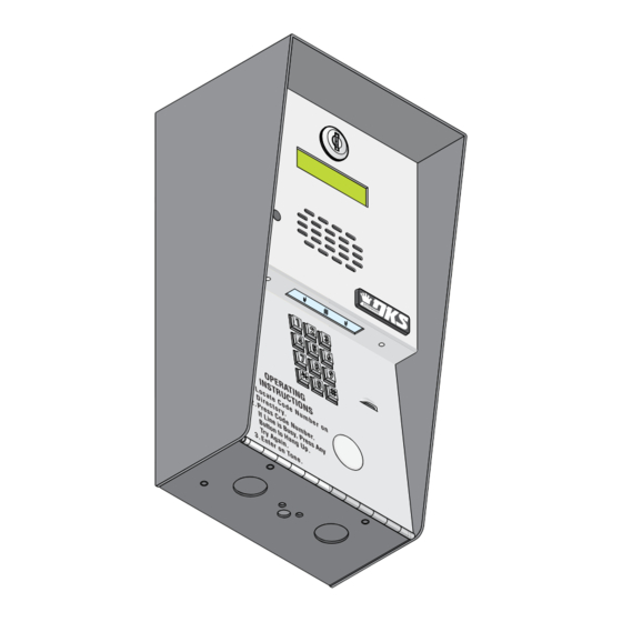
Installation/Owner's Manual
Use this manual for circuit board 1862-010 Revision L or higher.
1802
1802
1802
1802EPD
1802EPD
1802EPD
Electronic Programmable Directory
Date Installed:
Installer/Company Name:
Phone Number:
Leave Manual with Owner
UL Listed
S u
r f a
c e
M o
u n
t
Circuit Board
Serial Number
and Revision Letter:
Copyright 2014 DoorKing, Inc. All rights reserved.
Model 1802 & 1802EPD
Model 1802 & 1802EPD
Model 1802 & 1802EPD
Telephone Entry System
Control a main entry point plus an additional entry point.
F l u
Copyright 2009 DoorKing, Inc. All rights reserved.
1802-065-D-10-14
s h
M o
u n
t
Advertisement
Chapters
Table of Contents

Related Manuals for DKS 1802


Summary of Contents for DKS 1802
- Page 1 Installation/Owner’s Manual Model 1802 & 1802EPD Model 1802 & 1802EPD Model 1802 & 1802EPD Telephone Entry System Use this manual for circuit board 1862-010 Revision L or higher. 1802-065-D-10-14 Control a main entry point plus an additional entry point. 1802...
-
Page 3: Specifications
1802EPD has A and Z scroll buttons and a big CALL button to simplify use. • 1802 can provide service for up to 1000 residents. 1802EPD provides service for up to 100 residents. • 1802 and 1802EPD are programmed from the front keypad. Both can be programmed remotely using a touch-tone telephone. -
Page 4: Table Of Contents
Programming Area Codes (Area Code Reference Numbers) 3.2.4 Programming Area Codes WITH Area Code Reference Numbers 3.2.5 Deleting Individual Phone Number 3.2.6 Deleting ALL Phone Numbers 3.2.7 Display / Delete Phone Numbers with UNKNOWN Directory Codes 3.2.8 Display Phone Numbers with KNOWN Directory Codes 1802-065-D-10-14... - Page 5 Phone Line Sharing for Multiple Telephone Entry Systems 4.3.4 Connection to a PBX 4.3.5 Areas with 10-Digit Dialing SECTION 5 - MAINTENANCE 5.1 Replacement Parts 5.2 Troubleshooting 42-43 5.3 Accessories 1802 Wiring Schematic 1802EPD Wiring Schematic SECTION 6 - LOG TABLES 46-48 RESIDENT INSTRUCTIONS 1802-065-D-10-14...
- Page 6 DoorKing does not provide a power transformer on units sold outside of the United States. Use only transformers that are listed by a recognized testing laboratory to power the telephone entry system. An Inherently Protected Transformer must be used to power this device. 1802 and 1802EPD systems require a 16.5-volt, 20 VA transformer. Listing: This product has been tested to and found to be in compliance with the UL 294 Safety Standard by Intertek Testing Services NA Inc.
- Page 7 Instruct the end user to read and follow these instructions. Instruct the end user to never let children play with or operate any access control device. This Owner’s Manual is the property of the end user and must be left with them when installation is complete. 1802-065-D-10-14...
-
Page 8: Section 1 - Installation
1.1 General Installation There are 2 different styles of the 1802 telephone entry system (Surface and Flush mounts), and different ways to mount them (On a wall, in a wall, attached to a architectural style post, kiosk, etc). Models will ALL need a telephone line, power and communication wires run to them in conduit or inside a architectural style post. -
Page 9: Remove Components From Enclosure
1.1.1 Remove Components from Enclosure There are 2 different models of the 1802 telephone entry system - Standard 1802 and 1802EPD which has an electronic programmable directory with scroll buttons. 1. Disconnect the keypad ribbon cable from the circuit board. Disconnect... -
Page 10: Install Enclosure
1.1.2 Install Enclosure t i n There are 2 different styles of the 1802 telephone entry system - c r e ( N o surface and flush mount. The illustrations below show typical t s u Mount a Surface l i e d installations but specific installations can vary from this. -
Page 11: Surface Mount Dimensions
1.2 Surface Mount Dimensions Surface mount units can be mounted directly to a wall, pilaster, post mounted using a DoorKing Adapter Plate (P/N 1802-111) with DoorKing mounting posts (P/N 1200-036, 1200-045, 1200-0046 and 1200-049). Be sure the unit is mounted securely and is not subject to vibration from closing doors or gates. -
Page 12: Flush Mount Dimensions
Rough-In Box Back View Front View Back View Side View 12.5” 14” 12” PQRS PQRS WXYZ WXYZ 3.875” 3” 3.875” OPER OPER CALL .875” Dia 6.875” 3.375” 8.375” 3” 3.25” .875” Dia 1.75” 1.25” Dia Bottom View Bottom View 1802-065-D-10-14... -
Page 13: Memory Chip Replacement
1.4 Memory Chip Replacement The 1802 is shipped with the memory chip already installed in the unit. However, if you need to replace the chip, follow the instructions below. CAUTION Power MUST be OFF to the Circuit Board!! DO NOT install the memory chip with power to the telephone entry system turned ON. -
Page 14: Postal Lock Installation
E x i l o c t e l e t h e Relay Activates 1802-065-D-10-14... -
Page 15: Section 2 - Wiring
DO NOT run high voltage (115 V) power lines and low voltage/communication lines in the same conduit. These should be in separate conduits at least six (6) inches apart. Be sure that all phone line wiring is twisted and completely isolated from ground. 1802-065-D-10-14... -
Page 16: Grounding
To install the ferrite filter, release the clip on the side to open the i n a e r m 1 6 A filter, place the wires in the circular core and snap the filter closed. i n T 1 6 A B A T Power Wires 1802-065-D-10-14... -
Page 17: Terminal Descriptions
Relay 2 3 2 1 to activate for the programmed strike time or 3 2 1 dial a preprogrammed TONE phone number (see section 3.1.8). Relay 2 Terminal RING TONE Non-Removable Main Terminal PHONE CGND MICG SPKR COM 16AC 16AC 1802-065-D-10-14... -
Page 18: Telephone Entry System Wiring And Adjustments
Normally Closed (NC) Lock relay input. Gate Operator is wired to Power for electric strike or magnetic Normally Open Lock Power lock is NOT provided by the system. (NO) relay UL listed Use separate UL listed power supply. input. 1802-065-D-10-14... -
Page 19: Speaker Volume, Microphone And Feedback
Note: Approximately 30 seconds after the master code switch is turned ON, the system will signal a long tone. This is normal and can be ignored. After the master code switch is turned OFF, the display will read MST CODE for approximately 30 seconds. 1802-065-D-10-14... - Page 20 For a system with a Hand Set (HS), the jumper is set in the left position from the factory. An optional handset kit (P/N 1807-012) is available for the surface mount 1802 ONLY. DO NOT place jumpers on both the HS and HF pins at the same time.
-
Page 21: Section 3 - Programming
(beeeeeep) will be heard. The amount of telephone numbers that can be programmed into the standard 1802 system is dependent on the memory size ordered. Memory sizes available are 125 - 500 - 1000. The 1802EPD model has a standard memory size of 100. The memory size also determines the number of four-digit entry codes (memory size + 12) that can be programmed into the system. - Page 22 Programming Time Clock 3.5.1 * 33 Automatic Relay Activation Time Zones 3.5.2 * 35 * 36 Four-Digit Entry Codes Time Zone 3.5.3 Five-Digit Entry Codes Time Zone 3.5.4 * 37 “Flash Entry Codes” Active for ONE-DAY ONLY 3.5.5 * 15 1802-065-D-10-14...
-
Page 23: Single Or Multiple Systems
MASTER CODE (beep). 2. Enter the three-digit talk time in seconds (001-255), then press (beep). (Example: 1 second - enter 001, 20 seconds - enter 020 etc.) OPER OPER 3. Press together to end this programming sequence (beeeeeep). 1802-065-D-10-14... -
Page 24: Tone Open Numbers
(beep) to set Switch Input 2. OPER OPER 3. Press (beep) to set to activate the relay, OR (beep) to set the switch input to dial-out a preprogrammed phone number. OPER OPER 4. Press together to end this programming sequence (beeeeeep). 1802-065-D-10-14... -
Page 25: Number Of Rings Before Telephone Entry System Will Answer
2. Enter the single-digit desired key number, then press (beep). OPER OPER 3. Press (beep) for hang-up, OR (beep) for touch-tone. 4. Repeat steps 2 and 3 to program other keys. OPER OPER 3. Press together to end this programming sequence (beeeeeep). 1802-065-D-10-14... -
Page 26: System To Stay On-Line Or Hang-Up After Touch-Tone Number Pressed
2. Enter the directory code digit length (1, 2, 3 or 4), then press (beep). OPER OPER 3. Press (beep) to cancel this function, OR (beeeeeep) to confirm the change. The programming sequence will automatically end itself after pressing . This CANNOT be UNDONE! 1802-065-D-10-14... -
Page 27: Programming 7-Digit Phone Numbers
(beeeeeep). Use these tables to keep track of area codes programmed in. Complete log table in back of manual when finished. Area Code Reference Number Area Code Area Code Reference Number Area Code 1802-065-D-10-14... -
Page 28: Programming Phone Numbers With Area Code Reference Numbers
This programming step CANNOT be UNDONE! 1. Press and enter your four-digit MASTER CODE (beep). WXYZ WXYZ WXYZ WXYZ WXYZ WXYZ WXYZ WXYZ 2. Enter , then press (beep). This CANNOT be UNDONE! This programming sequence will automatically end itself by a long (beeeeeep). 1802-065-D-10-14... -
Page 29: Display / Delete Phone Numbers With Unknown Directory Codes
If the first digit is flashing, this is the area code reference number and indicates that the number displayed is a long distance phone number. 4. To display additional phone numbers press and repeat step 2. OPER OPER 5. Press together to end this programming sequence (beeeeeep). 1802-065-D-10-14... -
Page 30: Programming Messages And Names (1802Epd Only)
WXYZ WXYZ WXYZ WXYZ WXYZ WXYZ WXYZ WXYZ WXYZ WXYZ Space Clear Skip Name 1802-065-D-10-14... -
Page 31: Programming The Welcome Message
16 characters each. The example below shows how the sample message was divided into three lines. Use the blank matrix to organize your own message. Default Welcome Message = WELCOME TO THE DKS PHONE SYSTEM HAVE A NICE DAY Example: WELCOME TO THE DKS PHONE SYSTEM HAVE A NICE DAY... -
Page 32: Programming The Instruction Message
Default Instruction Message = PUSH A Z TO FIND NAME THEN PUSH THE CALL BUTTON 1. Press and enter your four-digit MASTER CODE (beep). OPER OPER 2. Press (beep) to reset the message to default, OR (beep) to keep the current programmed message. 1802-065-D-10-14... -
Page 33: Programming Names
6. Repeat steps 2, 3, 4, and 5 to enter additional names. OPER OPER 7. Press together to end this programming step. The LCD display will read: SORTING. System alphabetizes the names. This may take a few minutes. Sorting is complete when a long (beeeeeep) is heard. 1802-065-D-10-14... -
Page 34: Delete A Single Name
OPER OPER 2. Press to erase all names, OR to keep all names. 3. When you press in step 2, The LCD display will read: ERASING. Erasing is complete when a long (beeeeeep) is heard. This CANNOT be UNDONE! 1802-065-D-10-14... -
Page 35: Entry Code Programming
Factory default divide number is 9999 - Activates Relay 1. 1. Press and enter your four-digit MASTER CODE (beep). 2. Enter the four-digit divide number, then press (beep). OPER OPER 3. Press together to end this programming sequence (beeeeeep). 1802-065-D-10-14... -
Page 36: Programming Five-Digit Entry Code
Factory default divide number is 99999 - Activates Relay 1. 1. Press and enter your four-digit MASTER CODE (beep). 2. Enter the five-digit divide number, then press (beep). OPER OPER 3. Press together to end this programming sequence (beeeeeep). 1802-065-D-10-14... -
Page 37: Time Functions Programming
Example 2, to have a time zone active on Monday thru Friday ONLY (Mon = 2, Tues = 3, ..Fri = 6), enter 2 3 4 5 6 # #. 9. Repeat steps 2 through 8 to enter additional time zones. OPER OPER 10. Press together to end this programming sequence (beeeeeep). 1802-065-D-10-14... -
Page 38: Four-Digit Entry Codes Time Zone
9. Enter the UPPER four-digit entry codes boundary number, then press (beep). Entry codes HIGHER than this number will NOT activate relays when the entry code time zone is ON. OPER OPER 10. Press together to end this programming sequence (beeeeeep). 1802-065-D-10-14... -
Page 39: Five-Digit Entry Codes Time Zone
3. Enter the two-digit day of the month that the code is to be active, then press (beep). 4. Enter a desired four-digit FLASH ENTRY CODE, then press (beep). 6. Repeat steps 2 through 4 to enter additional desired FLASH ENTRY CODES. OPER OPER 4. Press together to end this programming sequence (beeeeeep). 1802-065-D-10-14... -
Page 40: Section 4 - System Operating Instructions
Guests will locate a residents name and directory code in a directory associated with the standard 1802. This may be a letter board type directory, an add-on directory or a built-in directory like that found in the 1810 unit. When a directory code is entered on the keypad,the telephone entry system will call the prepro- grammed telephone number stored under that directory code. -
Page 41: System Administrator
4. Press the programmed single-digit tone number to deactivate the relay (beep heard). The system will automatically hang up. Note: the single-digit tone number is dependent on the programming in 3.1.6 (factory defaults: Relay 1 - 7, Relay 2 - 3). 1802-065-D-10-14... -
Page 42: Remote Entry Code Time Zone Enable / Disable
4. Press 0 (beep heard) to turn the time zone OFF, or press 1 (beep heard) to turn the time zone ON. 5. Hang up the phone or if at the system keypad, press 0 # together (beeeeeep). 1802-065-D-10-14... -
Page 43: Miscellaneous Operating Instructions
(beep). Then program the outside phone number as a long distance number (section 3.2.4) using the area code reference number used to program 310 as one of the alternate area codes. Program additional area codes and phone numbers as described in sections 3.2.3 and 3.2.4. 1802-065-D-10-14... -
Page 44: Section 5 - Maintenance
Replacement Circuit Board P/N 1862-010 REV L or higher. LCD display is NOT INCLUDED. Keypad Replacement keypads – 1802 P/N 1895-017 num only, 1802EPD P/N 1895-016 num & letters Transformer Replacement power transformer – 16.5 VAC, 20 VA U.L. Listed DoorKing P/N 1804-060 5.2 Troubleshooting... - Page 45 Re-program relay 1 low and high ranges. FOUR-digit codes (3.4.4), FIVE-digit codes (3.4.8). activate relay 2. System emits a beep • Master code switch is in the ON position. Turn master code switch OFF (2.3.4). every 30 seconds. LCD is unreadable • Adjust contrast. (2.3.3). 1802-065-D-10-14...
-
Page 46: Accessories
High voltage (115 V) suppressor. P/N 1879-080. 1802EPD Heater Kit 1802 Adapter Plate Allows the 1802EPD Telephone Entry System LCD display to Needed when mounting to mounting posts. P/N 1802-111. maintain normal operation to approximately -20°F (-29°C). P/N 2600-582. Mounting Posts & Kiosk Off-Set pad mount. -
Page 47: 1802Epd Wiring Schematic
3 2 1 3 2 1 CALL TONE Yellow RING TONE PHONE CGND MICG SPKR 16AC 16AC Phone Line Ground White Blue Green 1998-010 Postal Lock Switch (Switch Input 1) Microphone White Green LED Keypad Light Gray Orange White Purple Speaker 1802-065-D-10-14... -
Page 48: Relay 1= 9 8 7
Upper Boundary # Upper Boundary # Automatic Relay Activation Time Zones (section 3.5.2) Zone 1 - Relay 1 Zone 2 - Relay 1 Zone 3 - Relay 2 Zone 4 - Relay 2 Beginning Time Ending Time Days of the Week 1802-065-D-10-14... - Page 49 Residents Information Make additional copies of this table as needed. Alternate Area Code may be needed, see sections 4.3.4 and 4.3.5 for more information. NAME AREA CODE PHONE NUMBER DIRECTORY CODE ENTRY CODE ALT. AREA CODE 1802-065-D-10-14...
- Page 50 Residents Information Make additional copies of this table as needed. Alternate Area Code may be needed, see sections 4.3.4 and 4.3.5 for more information. NAME AREA CODE PHONE NUMBER DIRECTORY CODE ENTRY CODE ALT. AREA CODE 1802-065-D-10-14...
-
Page 51: Resident Instructions
To use your access code, first press the key, and then enter your four-digit code System Administrator’s Note: Fill in the phone number and access granted number above, copy and distribute this sheet to the residents. 1802-065-D-10-14... -
Page 52: 1802-065
Installation/Owner’s Manual Model 1802 & 1802EPD Model 1802 & 1802EPD Model 1802 & 1802EPD Telephone Entry System Use this manual for circuit board 1862-010 Revision L or higher. 1802-065-D-10-14 Control a main entry point plus an additional entry point. www.doorking.com DoorKing, Inc.
Need help?
Do you have a question about the 1802 and is the answer not in the manual?
Questions and answers