Table of Contents
Advertisement
Advertisement
Table of Contents

Related Manuals for DKS 1803


Summary of Contents for DKS 1803
- Page 1 Owner’s Manual 1803, 1808, 1810 Telephone Entry Systems DoorKing, Inc. 120 Glasgow Avenue Inglewood, California 90301 U.S.A. Phone: 310-645-0023 Fax: 310-641-1586 www.doorking.com P/N 1800-060 REV S, 3/14 Copyright 2001 DoorKing, Inc. All rights reserved.
- Page 2 Page 2 1800-060-S-3-14...
- Page 3 Use this manual with the following models only. All 1803, 1808 and 1810 Telephone Entry Systems with circuit board 1862-010, Rev I or higher. DoorKing, Inc. reserves the right to make changes in the products described in this manual without notice and without obligation of DoorKing, Inc. to notify any persons of any such revisions or changes.
- Page 4 Page 4 1800-060-S-3-14...
- Page 5 QUICK START Mount the Telephone Entry System. If the unit is being used to provide access through an automated vehicular gate, the unit must be mounted at least 10-feet away from the gate. See pages 11-20. Connect 16 VAC power to terminals 13-14. Connect a dedicated touch-tone loop-start phone line to terminals 1-2.
-
Page 6: Table Of Contents
Section 1 – Installation Installation Guidelines ..........................11 Surface 1803 and 1810 Mount Units ......................12 Surface Mount 1803 and 1810 Units with Recess Box ................13 Flush Mount 1803 and 1810 Units......................14 Flush Mount Rough-in Box (1803 and 1810 only) ..................15 Flush Mount Trim Ring (1803 and 1810 only) ..................16 Flush Mount Surface Mounting Kit (1803 and 1810 only) ................17... - Page 7 Phone Number Programming 3.2.1 Directory Code Length ......................32 3.2.2 7-Digit Phone Numbers ......................32 3.2.3 Area Codes ..........................33 3.2.4 Phone Numbers with Area Code Reference ................33 3.2.5 Deleting Individual Phone Numbers..................33 3.2.6 Delete All Phone Numbers .......................34 3.2.7 Display / Delete Phone Numbers .....................34 3.2.8 Display Phone Numbers with Known Directory Code ..............34 Entry Code Programming...
-
Page 8: Important Notices
DoorKing does not provide a power transformer on units sold into Canada. Use only transformers that are CSA listed to power the telephone entry system. 1802, 1803, 1808, 1810, 1814, 1815, 1818 and all "P" series systems require a 16.5-volt, 20 VA transformer. The models 1816 and 1817 require a 16.5-volt, 40 VA transformer. -
Page 9: Important Information
IMPORTANT INFORMATION Prior to beginning the installation of the telephone entry system, we suggest that you become familiar with the instructions, illustrations, and wiring guidelines in this manual. This will help insure that you installation is performed in an efficient and professional manner. ... -
Page 10: Features
FEATURES Can provide service for up to 1000 residents. System can be programmed from the front keypad or remotely using a touch-tone telephone. System keypad will emit DTMF tones after a call is answered allowing the system to be used with auto-attendants, answering machines, etc. -
Page 11: Section 1 - Installation
SECTION 1 - INSTALLATION Order your telephone line at least two weeks prior to the planned installation date. This will assure that a phone line is available when the unit is installed. The telephone company will require the following information from you: Type: Touch Tone, Loop Start Ringer Equivalence:... -
Page 12: Surface 1803 And 1810 Mount Units
Surface Mount 1803 and 1810 Units Surface mount units can be mounted directly to a wall or pilaster, or can be post mounted using a DoorKing Architectural Style heavy-duty mounting post (p/n 1200-037 and 1200-038). Be sure the unit is mounted securely and is not subject to vibration from closing doors or gates. -
Page 13: Surface Mount 1803 And 1810 Units With Recess Box
Surface Mount 1803 and 1810 Units with Recess Box Surface mount units can be semi-flush mounted into a wall or pilaster by using the optional recess- mounting box (p/n 1803-150). Be sure the unit is mounted securely and is not subject to vibration from closing doors or gates. -
Page 14: Flush Mount 1803 And 1810 Units
Flush Mount 1803 and 1810 Units Flush mount units are installed into a wall with flush mount kits 1814-165 (stainless) or 1814-166 (gold). Flush mount kits are not included with the entry system. Flush mount units are not designed for direct exposure to the weather. Be sure the unit is mounted securely and is not subject to vibration from closing doors or gates. -
Page 15: Flush Mount Rough-In Box (1803 And 1810 Only)
Flush Mount Rough-in Box (applies to 1803 and 1810 only) The flush mount installation kit has two parts; the rough-in box and the trim ring. The rough-in box is installed first. Flush Mount Rough-in Box (Flush mount rough-in box is included with the 1814-165 and 1814-166 flush mount kits) 12.800... -
Page 16: Flush Mount Trim Ring (1803 And 1810 Only)
Flush Mount Trim Ring (use with 1803 and 1810 units only) Flush mount units can be mounted by using the 1814-165 (stainless) or 1814-166 (gold) mounting kit. Flush mounting kits are not included with the unit. Flush mount units are not designed for direct exposure to the weather. -
Page 17: Flush Mount Surface Mounting Kit (1803 And 1810 Only)
Flush Mount Surface Mounting Kit (use with 1803 and 1810 units only) Flush mount units can be surface mounted by using the optional 1814-152 surface mount trim ring. Flush mount units are not designed for direct exposure to the weather. Be sure that the unit is securely mounted and is not subject to vibration from closing doors or gates. -
Page 18: 1808 Surface Mount
1808 Surface Mount Only Surface mount units can be mounted directly to a wall or pilaster, or can be post mounted using a DoorKing mounting post (p/n 1200-045 and 1200-046). Be sure the unit is mounted securely and is not subject to vibration from closing doors or gates. WARNING! If this entry system is used to control a vehicular gate with an automatic gate operator, the entry system must be mounted a minimum of ten (10) feet away from the gate and gate operator, or in such a way that a... -
Page 19: Memory Chip Installation
Memory Chip Installation The telephone entry system is shipped with a memory chip packaged in a separate box inside the shipping container. The memory chip must be installed for the telephone entry system to operate. CAUTION!! Do not install the memory chip with power to the telephone entry system turned on. -
Page 20: Postal Lock Installation
The installer or the building owner/manager will have to call the Post Office and arrange for the installation of this lock into the telephone entry system. The 1802, 1803 and 1810 units are all pre-wired to accept the installation of the postal lock. -
Page 21: Section 2 - Wiring & Adjustments
SECTION 2 – WIRING & ADJUSTMENTS Prior to installing wiring to the telephone entry system, we suggest that you become familiar with the instructions, illustrations, and wiring guidelines in this manual. This will help insure that you installation is performed in an efficient and professional manner. The wiring of the telephone entry panel is an extremely important and integral part of the overall access control system. -
Page 22: Circuit Board Adjustments
Circuit Board Adjustments 1862-010 Control Board Adjustments CONTRAST DISPLAY SWITCH 2 INPUT A-Z-CALL BUTTON CONNECTOR Master Code CLICK SENS KEYPAD CONNECTOR VOLUME FEEDBACK SPEAKER VOLUME REV H Boards and later. RELAY 2 REV I Boards and later. TERMINALS Used on 1802-EPD model only. May be a toggle switch on older boards. -
Page 23: Wiring Diagram
Wiring Diagram Field Wire Diagram - 1862-010 Control Board Gate Operator Strike / Lock Mag Lck 1862-010 Circuit Board SWITCH 2 INPUT NO NC COM RELAY 2 CONTACTS MAIN TERMINAL 10 11 12 13 14 Phone Line Wiring Max Distance Power Wiring Max Distance Phone 800 Feet... -
Page 24: Main Terminal Description
Terminal Description MAIN DESCRIPTION TERMINAL Phone Line Connection – 800 ft. maximum with 24 AWG wire; 1600 ft. maximum with 22 AWG wire. Phone Line Connection – 800 ft. maximum with 24 AWG wire; 1600 ft. maximum with 22 AWG wire. Earth Ground Only –... -
Page 25: Adjustments
2.4.5 Display Contrast (1803, 1810 only) 1. Open the front of the telephone entry system and locate the contrast adjustment. 2. Turn the master code switch on. The display will read MST CODE. While the display is lighted, turn the contrast potentiometer clockwise and then counter clockwise until the display is satisfactory. -
Page 26: Master Code Switch
30 seconds. This tone will continue every 30 seconds until a new master code is entered, or until the switch is turned off. After the switch is turned off, the display (1803, 1810 only) will remain lit for approximately 30 seconds, and then will go off. -
Page 27: Section 3 - Programming
(beep) tones when programming steps have been followed correctly, and with a long tone (beeeeeep) when the programming step is ended. The 1803 and 1810 systems have an LCD display that will prompt you for information that you will need to enter. -
Page 28: General Programming
General Programming 3.1.1 Master Code This programming step sets the system MASTER CODE. The master code is the four-digit number required to gain access to the system memory. You need to know the master code prior to performing any of the programming functions on the following pages. NOTE: The master code cannot be programmed from an off-site location. -
Page 29: Talk Time
3.1.5 Talk Time This programming sequence sets the maximum time allowed for conversation when the entry system places a call to the resident. The talk time can be set from 1 second up to 255 seconds (4 minutes, 15 seconds) and is entered as a three-digit number. For example, to set a talk time of 20 seconds, enter 020 in step 3. -
Page 30: Program Switch Inputs To Activate A Relay Or Dial-Out A Phone Number
3.1.7 Switch Input Programming This programming sequence will set how the two switch inputs on the telephone entry system control board will operate. Switch input 1 is labeled PSW (postal switch) and is found on terminal 4 of the main terminal strip. Switch input 2 is a two terminal auxiliary input located on the upper left hand corner of the control board. -
Page 31: 3.1.11 Keypad Function
3.1.11 Keypad Function This programming sequence sets the function of the 0 through 9, and the # keys on the keypad during conversation. The keys can be set to hang-up the entry system when they are pressed during conversation, or they can be programmed to DTMF tone out during conversation. The later may be desirable if the entry system is used with an auto-attendant type telephone system where the caller is prompted to enter numbers from a touch-tone telephone. -
Page 32: Phone Number Programming
Phone Number programming 3.2.1 Programming the Directory Code Length This programming sequence sets the directory code length to 1 - 2 - 3 or 4 digits. If 11 or more resident names or telephone numbers are going to be programmed into the system, the directory code must be at least two-digits. -
Page 33: Area Codes
3.2.3 Programming Area Codes Up to 15 different area codes can be programmed for any 10-digit or long distance calling requirements and will be referenced 01 through 15. The area codes will be entered as a four-digit number (1 + the three digit area code). If area codes are being programmed to facilitate 10-digit calling requirements, precede the three-digit area code with #. -
Page 34: Delete All Phone Numbers
Press *22 and enter the four-digit MASTER CODE _ _ _ _ (beep). Press 9999 then press * (beep). This programming sequence will automatically end itself. This will be indicated by a long tone (beeeeeep). Sections 3,2,7 and 3.2.8 apply only to 1803 and 1810 units. 3.2.7 Display / Delete Phone Numbers This program sequence is useful to display phone numbers when you do not know what directory code they have been programmed under. -
Page 35: Four-Digit Entry Code Programming
Entry Code Programming 3.3.1 Four-Digit Entry Code Programming This programming sequence programs four-digit entry codes into the system memory. The number of four-digit entry codes that can be programmed is the same as the telephone number memory capacity, plus 12. We suggest that all entry codes that are programmed into the system be listed with the names of persons that they have been assigned to (see appendix). -
Page 36: Five-Digit Entry Code Programming
3.3.5 Five-Digit Entry Code Programming This programming sequence programs five-digit entry codes into the system memory. The number of five digit entry codes that can be programmed is limited to six. We suggest that all entry codes that are programmed into the system be listed with the names of persons that they have been assigned to (see appendix). -
Page 37: Time Functions Programming
Time Functions Programming 3.4.1 Time Clock Programming This programming sequence programs the calendar chip in the telephone entry system for the current time and date. The calendar chip must be programmed if you are going to use any of the time functions available with the entry system. -
Page 38: Four-Digit Entry Code Time Zone
3.4.3 Four-Digit Entry Code Time Zone This programming sequence sets up a time zone for the four-digit entry codes. This time zone uses a range of four-digit entry codes and can be programmed for certain days of the week. This time zone can be turned on and turned off after it is programmed (see operating instructions 4.2.4). -
Page 39: Flash Entry Codes
3.4.5 Flash Entry Codes This programming sequence sets up "FLASH" four-digit entry codes. Flash codes are entry codes that will operate on a specific day of the month only - they will not operate before or after the programmed day. The flash code will be valid for a single 24-hour period only. For example, if you program a flash code on July 1st to be active on the 10th, the code will become valid at 00:00 AM on July 10th and expire at 11:59 PM. - Page 40 Page 40 1800-060-S-3-14...
-
Page 41: Section 4 - Operating Instructions
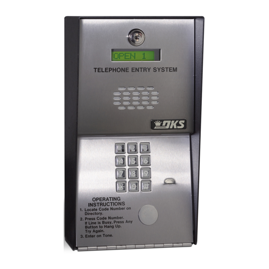
SECTION 4 – OPERATING INSTRUCTIONS Never allow children to operate or play with any access control device. General Instructions 4.1.1 Guest Instructions Instructions on the faceplate of the unit will instruct guest on the operation of the telephone entry system. Guests will locate a residents name and directory code in a directory associated with the telephone entry system. -
Page 42: System Administrator
System Administrator The administrator can perform the following operations from a remote location using a touch-tone telephone. You must know the phone number of the system and the system master code. 4.2.1 Remote Programming 1. Call the telephone number that the entry system is installed on. The system will answer with a short tone (beep). -
Page 43: Entry Code Time Zone Enable / Disable
4.2.4 Entry Code Time Zone Enable / Disable The entry code time zones can be turned off or on remotely from a touch-tone telephone at any time without changing the time zone boundaries. To program the time zone boundaries, see sections 3.4.3 and 3.4.4. -
Page 44: Miscellaneous Operating Instructions
Miscellaneous Operating Instructions 4.3.1 Switch Input Operation The two switch inputs can be programmed to either activate their respective relay (switch 1 input activates relay 1; switch 2 input activates relay 2) or they can be programmed to call the phone number programmed under the first two directory codes (switch 1 input calls the phone number programmed under directory code 0, 00, 000 or 0000;... -
Page 45: Connection To A Pbx
4.3.4 Connection to a PBX If the telephone entry system is going to be connected to a PBX system, you may need to program extension numbers in place of a seven-digit telephone number. To do this, enter the extension number and fill the remaining spaces with the # key in the phone number programming step. For example, if the PBX system uses four-digit extensions and you want to program extension 2217 as a phone number, in step 3, section 3.2.2 press: 2 2 1 7 # # # * (beep). - Page 46 Page 46 1800-060-S-3-14...
-
Page 47: Replacement Parts
SECTION 5 – MAINTENANCE The DoorKing telephone entry system is essentially a maintenance free device. When the unit is properly installed, it should provide years of trouble free service. Maintenance is limited to updating the directory and phone number and/or entry codes when residents move in or out. The faceplate of the unit should be cleaned on a regular basis to keep contaminants in the air from sticking to the surface and possibly causing pitting. - Page 48 SYMPTON POSSIBLE SOLUTION(S) Cannot get into Wrong master code entered. Start over. programming mode. Waiting too long between pushing buttons. Enter information quicker. Keypad is not plugged into board correctly. Cable points down. Memory chips are installed upside down. ...
-
Page 49: Accessories
P/N 1803-150. Flush Kit Use to install flush style 1803 or 1810 units into a wall or column. Kit includes rough in back box and trim ring. P/N 1814-165 comes with stainless steel trim ring. P/N 1814-166 comes with gold plated trim ring. -
Page 50: Log Tables
Log Tables Complete the information in the tables on the following pages to maintain a record of the information that has been programmed into the telephone entry system if the system. Make copies of the resident log sheet so that you have enough to complete a listing of all residents and data. MASTER CODE RELAY STRIKE TIME RELAY 1... - Page 51 NAME PHONE DIRECTORY ENTRY ALTERNATE NUMBER CODE CODE AREA CODE 1800-060-S-3-14 Page 51...
- Page 52 NAME PHONE DIRECTORY ENTRY ALTERNATE NUMBER CODE CODE AREA CODE Page 52 1800-060-S-3-14...
-
Page 53: Resident Instruction Sheet
Resident Instruction Sheet Your building / community has been equipped with a DoorKing Telephone Entry System that will provide communication for your guest from the lobby door / gated entrance to your home by use of the local telephone etwork. ...
Need help?
Do you have a question about the 1803 and is the answer not in the manual?
Questions and answers