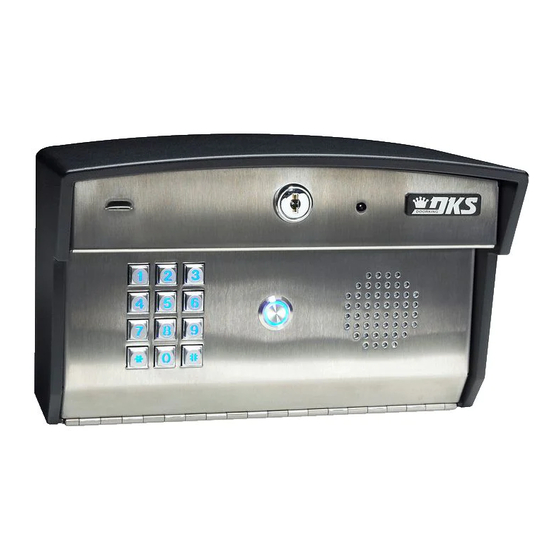
DKS 1812 Plus Installation & Owner's Manual
Residential telephone intercom/access control system
Hide thumbs
Also See for 1812 Plus:
- Owner's manual (63 pages) ,
- Installation & owner's manual (58 pages)
Table of Contents
Advertisement
Installation/Owner's Manual
Use this manual for circuit board 1971-010 Revision M or higher.
1
4
7
S u
r f a
c e
M o
u n
1
2
4
5
7
8
0
S u
r f a
c e
M o
Date Installed:
Installer/Company Name:
Phone Number:
Leave Manual with Owner
UL Listed
Residential Telephone Intercom/Access Control System
2
3
5
6
8
9
0
t C
u r v
e d
3
6
9
u n
t
Copyright 2011 DoorKing, Inc. All rights reserved.
Model 1812 Plus
Model 1812 Plus
Model 1812 Plus
W a
1
2
4
3
5
7
6
8
9
0
F l u
s h
Circuit Board
Serial Number
and Revision Letter:
Copyright 2009 DoorKing, Inc. All rights reserved.
1812-161-L-12-11
Control a main door and gate.
1
2
4
3
5
7
6
8
9
0
l l M
o u
n t
M o
u n
t
TM
Advertisement
Table of Contents
Troubleshooting

Related Manuals for DKS 1812 Plus


Summary of Contents for DKS 1812 Plus
- Page 1 Installation/Owner’s Manual Model 1812 Plus Model 1812 Plus Model 1812 Plus Residential Telephone Intercom/Access Control System Use this manual for circuit board 1971-010 Revision M or higher. 1812-161-L-12-11 Control a main door and gate. r f a l l M...
-
Page 3: Specifications
SPECIFICATIONS For Model 1812 Plus with circuit board 1971-010 Rev M or higher ONLY. Interface Board 1 9 7 2 - 0 J 3 J M IC Control Board Both Boards Together - 1971-010 1 9 7 0 - 0 Features •... -
Page 4: Surface Mount Dimensions
SPECIFICATIONS Surface Mount Dimensions Front View Side View Back View 10” 5.25” 2.5” 1 1 1 1 2 2 2 2 3 3 3 3 3 3 1.125” Dia 2.5” 6.125” 5” 3” 2.875” 875” Dia 1.75” 1.125” 1.125” Bottom View Surface Mount Curved Dimensions Front View Side View... -
Page 5: Wall Mount Dimensions
SPECIFICATIONS Wall Mount Dimensions Front View Side View Back View 2.5” 1.125” Dia 7.325” 2.5” 5.375” 3.375” 10.75” 3.5” Bottom View Flush Mount Dimensions Side Views Front Views Rough-In Box Flush Box Flush Box 1 1 1 1 2 2 2 2 3 3 3 3 3 3 Bolt holes (4) to secure flush box 7.5”... -
Page 6: Table Of Contents
Installation Guidelines and Safety Information SECTION 1 - INSTALLATION 1.1 Mount the 1812 Plus Different Mounting Configurations of the 1812 Plus Models 1.2 Install By-Pass Board for “Telephone Mode” Configurations 1.3 Telephone Line Wire 1.4 16.5 VAC Power Wiring ONLY! 1.5 Grounding and Surge Suppression... - Page 7 TABLE OF CONTENTS 2.5 Access Codes to Operate Access Control Devices 2.5.1 “Simple” Access Code Programming (24/7 Operation) 2.5.2 “Time Zone Restricted” Access Code Programming 2.5.3 Delete an Access Code (Simple and Time Zone Restricted) 2.5.4 Delete All Access Codes (Simple and Time Zone Restricted) 2.5.5 “Temporary”...
- Page 8 100. Notice: DoorKing does not provide a power transformer on units sold into Canada. Use only transformers that are CSA listed to power the telephone entry system. The model 1812 Plus requires a 16.5-volt, 20 VA transformer. 1812-161-L-12-11...
-
Page 9: General Information
General Information • Prior to beginning the installation of the telephone entry system, we suggest that you become familiar with the instructions, illustrations, and wiring guidelines in this manual. This will help insure that you installation is performed in an efficient and professional manner. •... -
Page 10: Section 1 - Installation
SECTION 1 - INSTALLATION Installation of the 1812 Plus Telephone Entry System involves the installation of the hardware, by-pass board, and the wiring of these components. Be sure that all dirt, metal or wood debris is removed from inside after mounting it. Any debris inside could damage the control board and cause the 1812 Plus system to malfunction during operation. -
Page 11: Different Mounting Configurations Of The 1812 Plus Models
Different Mounting Configurations of the 1812 Plus Models Surface and Wall mount models can be mounted directly to a wall, pilaster or post mounted using a DoorKing mounting post (there are several different styles available). The flush mount model is designed to be mounted into a pilaster, wall or kiosk. In any case, be sure it is securely mounted and is not subject to continuous vibration from closing doors or gates. - Page 12 Flush Mount in a Pilaster, Wall or Kiosk Mount rough-in box into the pilaster, wall or kiosk. Run conduit inside wall into bottom of rough-in box if desired. Use appropriate hardware (Not supplied) to secure the rough-in box in place. Bolt flush box into the rough-in box with 4 supplied bolts.
-
Page 13: Install By-Pass Board For "Telephone Mode" Configurations
1.2 Install By-Pass Board for “Telephone Mode” Configurations The 1812’s by-pass board provides a method to by-pass the 1812 and route the incoming telephone line directly to the homeowner’s phone. The By-Pass board IS NOT optional when using an incoming telephone line or internet (Telephone Mode) –... -
Page 14: Telephone Line Wire
1.3 Telephone Line Wire Be sure to observe electrical safety when working with phone lines. Phone lines carry electricity and the ring voltage can deliver a substantial jolt. The best policy is to disconnect the house phone from the phone company Network Interface Device (also known as ‘Demarcation Device’) before working on the wiring. -
Page 15: Vac Power Wiring Only
1.4 16.5 VAC Power Wiring ONLY! The 1812 Plus operates ONLY on 16.5 VAC. DO NOT power the 1812 with 24 volt AC power. Use the supplied power trans- former, 16 VAC, 20 VA (or U.L. listed equivalent) to power the telephone entry system. DO NOT power any other devices (electric strikes, magnetic locks, etc.) from the 1812’s power transformer. -
Page 16: Wiring One 1812 To A Telco Line - Telephone Mode
30 VAC maximum. (14-16) Power 16.5 (17-18) The 1812 Plus operates ONLY on 16.5 “Normally Close” with Maglock VAC. DO NOT power the 1812 with 24 (Terminal 15 and 16) Volt transformer or source voltage. “Normally Open” with Electric Strike... -
Page 17: Wiring One 1812 To The Internet - Telephone Mode
30 VAC maximum. (14-16) Power 16.5 (17-18) The 1812 Plus operates ONLY on 16.5 “Normally Close” with Maglock VAC. DO NOT power the 1812 with 24 (Terminal 15 and 16) Volt transformer or source voltage. “Normally Open” with Electric Strike... -
Page 18: Wiring Multiple 1812S: Telco/Internet - Telephone Mode
1.8 Wire Multiple 1812s: Telco/Internet - Telephone Mode Use the previous 2 page’s wiring diagrams and By-Pass Board ENTRY BY-PASS The By-Pass board is NOT optional and must be information to wire multiple 1812s except for installed as part of multiple 1812s “Telephone Mode” 1875-010 EARTH the By-Pass board’s “PHONE IN”... -
Page 19: Wiring A Single 1812 - Intercom Mode
Pedestrian Gate/Door Supplied Transformer Polarity does not matter. Electric The 1812 Plus operates ONLY on 16.5 VAC. Strike DO NOT power the 1812 with 24 Volt transformer or source voltage. Use the supplied power transformer, 16.5 VAC, 20 VA (or UL listed equivalent) to power the telephone entry system. -
Page 20: Wiring Multiple 1812S - Intercom Mode
1.10 Wiring Multiple 1812s - Intercom Mode Up to five (5) 1812s may be Connect to Homeowner’s Check Polarity of Telephone Line Telephone Check for polarity on the incoming telephone line to wired in series using the method each 1812 board and maintain polarity throughout Connect the 1st 1812’s PHONE OUT Homeowner’s Phone shown: 1st 1812’s PHONE IN to... -
Page 21: Main Terminal Description
For easy reference, refer to the chart on page 22 that list the various programming functions and their default settings. 2.1 Programming Methods The 1812 Plus can be programmed from the system keypad (Keypad on the 1812) or from a touch-tone telephone connected to the system. -
Page 22: Programming The Master Code
Programming Documentation Note: There are programming log sheets in the back of this manual to document your specific master code, and keep track of all other programming that is preformed to this 1812 Plus. Keep this with all other system documentation for future reference. -
Page 23: System Parameters Programming
Wait 30 seconds before calling back to program another feature. Off-Site Touch-Tone Telephone Follow these steps when programming the 1812 Plus from an Off-Site Touch-Tone Telephone. IMPORTANT The 1812 must be programmed to answer incoming calls, section 2.3.9. -
Page 24: Quick Reference Table
Quick Reference Table Page # Section Command Factory Settings Section 2.3 System Parameters Programming Phone Mode or Intercom Mode 2.3.1 * 0 6 1 (Phone Mode) Single or Multiple Systems 2.3.2 * 6 1 1 (Single System) System Attention Number 2.3.3 * 6 2 Single or Double Ring... -
Page 25: Phone Mode Or Intercom Mode
2.3.1 Phone Mode or Intercom Mode Factory setting is 1 (Phone Mode). The 1812 is normally connected in series with a resident’s incoming phone line, which supplies a constant source of DC voltage. When the 1812 is connected in this manner, program the unit for PHONE mode. If the 1812 is to be connected to an open C.O. -
Page 26: Talk Time
2.3.6 Talk Time Factory setting is 060 (60 Seconds). This programming sequence sets the maximum time allowed for conversation when the 1812 places a call to the resident’s house, or if call forwarding is active, or if any of the dial out numbers are used. Talk time can be set from 10 seconds up to 255 seconds (4 minutes, 15 seconds) and is entered as a three-digit number. -
Page 27: Answer Incoming Call On X Rings
2.3.9 Answer Incoming Call on X Rings Factory setting is 06 (6 Rings). This programming section sets the number of rings that the 1812 will allow to pass through the system before it picks up the call. The number of rings to answer can be set from 1 to 99 rings and must be entered as a two-digit number. For example, if you want the 1812 to answer the call after the sixth ring, enter 0 6 in step 2. -
Page 28: Set Call Forward Microphone Gain And Speaker Volume
2.3.13 Set Call Forward Microphone Gain and Speaker Volume Factory setting is 71 (7 - Microphone, 1 - Speaker). This adjustment is required only if call forward or directory code dialing is being used. This step will adjust the microphone gain (the remote handset loudness) and the speaker volume (the 1812 loudness) during call forwarding operation. -
Page 29: Access Codes To Operate Access Control Devices
2.5 Access Codes to Operate Access Control Devices 2.5.1 “Simple” Access Code Programming (24/7 Operation) This programming sequence programs “simple” access codes into the system memory. “Simple” access codes cannot be time zone restricted; they can ONLY be assigned to operate the 2 internal relays on a 24/7 basis using the relay strike time programmed in section 2.3.7. -
Page 30: Delete All Access Codes (Simple And Time Zone Restricted)
2.5.4 Delete All Access Codes (Simple and Time Zone Restricted) This programming sequence ONLY deletes ALL existing ”simple” and “time zone restricted” access codes that have been programmed into the system. “temporary” access codes CANNOT be deleted. If you require all “temporary” access codes to be deleted, use the programming sequence in 2.5.7. -
Page 31: Time Functions
Note: The clock / calendar chip in the 1812 Plus will keep time for approximately 48 hours if power to the system is lost or removed. -
Page 32: Call Forward On/Off Or Time Zone Activation
2.6.3 Call Forward - ON/OFF or Time Zone Activation This programming sequence turns the call forward feature ON/OFF or setup a time zone activation. You must have a call forward phone number programmed into the 1812 memory (See 2.6.2). 1. Press 3 7 and enter the MASTER CODE. -
Page 33: Automatic Relay Activation Time Zone Programming (Up To 4)
2.6.5 Automatic Relay Activation Time Zone Programming (Up to 4) Factory setting in step 3 is 0 (Time zones are OFF). This program sequence sets up time zones to automatically activate and deactivate relays. Up to four (4) time zone can be programmed, each of which can be assigned to the desired relay(s). -
Page 34: Miscellaneous
2.7 Miscellaneous 2.7.1 Restore Factory Settings This step will restore the factory settings for each of the programming parameters. See the “Quick Reference Table” on page 22 for all of the factory settings. The master code will remain intact after the factory settings have been restored. WARNING: Once started, this sequence will program ALL values to factory default. -
Page 35: Section 3 - Adjustments
SECTION 3 - ADJUSTMENTS Speaker Volume The speaker volume potentiometer is labeled SPEAKER VOL on the control board. The speaker volume should be adjusted for adequate sound. Adjusting the speaker volume too loud could cause feedback from the microphone. 1. Open the front of the telephone entry system and locate the speaker volume adjustment. 2. -
Page 36: Section 4 - User Instructions
SECTION 4 - USER INSTRUCTIONS 4.1 Resident Operating Instructions 4.1.1 Granting or Denying a Guest Access To place a call from the 1812 to the resident’s house, the guest simply presses the PUSH TO CALL button located on the faceplate, see previous page. Once the guest has been identified by voice communication, the resident may grant them access by pressing the appropriate tone open number, or they may deny access by simply hanging up. -
Page 37: Remote Operation
4.2 Remote Operation 4.2.1 Remote Programming (Home Phone or Off-Site Phone) The 1812 can be programmed and operated from a remote location (Home or off-site) using a touch-tone telephone. Be sure that the programming for the 1812 to answer an incoming call has not been disabled (see 2.3.9). Note: The 1812 master code cannot be programmed remotely –... -
Page 38: Initiate Talk And Listen To 1812 When It Has Not Been Activated
4.2.5 Initiate Talk and Listen to 1812 when it has not been activated The homeowner’s phone can establish direct communication to the 1812 (Talk and listen from the phone) without the 1812 being activated first (Typically a guest pressing the call button at the 1812 will activate it). This is useful when a normal telephone entry system transaction does not occur and the homeowner must initiate communication to the 1812 to talk and listen from it. -
Page 39: Phone Line Polarity
5.2 Phone Line Polarity ENTRY BY-PASS ENTRY ENTRY BY-PAS BY-PAS When troubleshooting 1812 operational problems, check SW W phone line polarity. Crossed polarities can affect system By-Pass Board EARTH 1875-010 PHONE IN #3 - DC Negative. operation. PHONE IN #4 - DC Positive. Phone Line Surge Suppressor PHONE OUT #5 - DC Positive. -
Page 40: Isolating Noise Problems
5.3 Isolating Noise Problems If noise or hum is present on the resident’s phone line after installation of the 1812 telephone intercom system, use the proce- dure on the next page to find and correct the source of the noise. This procedure will require the use of a telephone test set (DoorKing P/N 1800-050 or equivalent). - Page 41 Symptom Possible Solution(s) Dial tone is heard on the • The system is not wired in series with the resident phone line. Check the PHONE IN terminals (1 & 2) 1812 speaker. and the PHONE OUT terminals (4 & 5). Buzz or noise on the line.
-
Page 42: Wiring Schematic
5.5 Wiring Schematic Keypad MASTER CODE Wire Right 1972-011 MIC VOL J3 10-Pin Keypad Plug Position on Circuit Board - Red Wire Left SPEAKER 1970-010 Speaker 1 2 3 4 5 6 7 8 910 Microphone J2 11-Pin Door Accessories Plug 1998-010 Purple White... -
Page 43: Programmed Information Log Sheets
Complete the information in the tables on the following pages to maintain a record of the information that has been programmed into the 1812 Plus entry system. 1812 Plus manual is available on-line at: www.dkaccess.com if extra log sheets are required. - Page 44 Directory Codes 24 – 50 / Dial-Out Phone Numbers Directory Code Name Phone Number 1812-161-L-12-11...
- Page 45 1-25 Access Codes Log Sheet (With Phone Numbers) Time Zone Restricted Information Access Code # and Name / Phone Number (Optional) Type: Simple or Time Zone Relay: Momentary Time Zone Restricted Number or Hold (Latch) 1812-161-L-12-11...
- Page 46 26-50 Access Codes Log Sheet (With Phone Numbers) Time Zone Restricted Information Access Code # and Name / Phone Number (Optional) Type: Simple or Time Zone Relay: Momentary Time Zone Restricted Number or Hold (Latch) 1812-161-L-12-11...
- Page 47 1-25 Access Codes Log Sheet (Access Only) Time Zone Restricted Information Access Code # and Name Type: Simple or Time Zone Relay: Momentary Time Zone Restricted Number or Hold (Latch) 1812-161-L-12-11...
- Page 48 26-50 Access Codes Log Sheet (Access Only) Time Zone Restricted Information Access Code # and Name Type: Simple or Time Zone Relay: Momentary Time Zone Restricted Number or Hold (Latch) 1812-161-L-12-11...
- Page 49 1-10 Temporary Access Codes Log Sheet Relay: Temporary Beginning Ending Time Zone Momentary Name Access Code # Date Date Number or Hold (Latch) 1-10 Temporary Access Codes Log Sheet extra log sheet Relay: Temporary Beginning Ending Time Zone Momentary Name Access Code # Date Date...
-
Page 50: 1812-161
Installation/Owner’s Manual Model 1812 Plus Model 1812 Plus Model 1812 Plus Residential Telephone Intercom/Access Control System Use this manual for circuit board 1971-010 Revision M or higher. 1812-161-L-12-11 www.doorking.com Copyright 2009 DoorKing, Inc. All rights reserved.
Need help?
Do you have a question about the 1812 Plus and is the answer not in the manual?
Questions and answers