Table of Contents
Advertisement
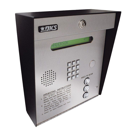
Installation/Owner's
Manual
S u
r f a
Date Installed:
Installer/Company Name:
Phone Number:
Leave Manual with Owner
UL Listed
Model 1834 PC Programmable
Model 1834 PC Programmable
Model 1834 PC Programmable
T E
L E
P H
O N
E E
N T
R Y
S Y
S T
E M
S P S P
1
A B
A B
C
C
2
G H
G H
D E
D E
F
F
4
I
I
3
J K
J K
L
L
5
P Q
P Q
M N
M N
R S
R S
O
O
7
6
O P
T U
T U
V
V
8
E R
1 .
W X
W X
A T
U s
Y Z
Y Z
9
I N
e
N a
" A
G
O P
O P
E R
E R
m e
I N
0
t o
N a
S T
a n
Z "
2 .
m e
d C
R U
B u
T o
s a
o d
t t o
C T
C a
r e
e N
n s
K e
I O
l l ,
I n
u m
y p
A l
t o
N S
E n
b e
L i n
a d
p h
L o
r o
t e
e i
o r
a b
n D
c a
r C
H a
s B
e t i
H O
P r
i s p
t e
o d
3 .
n g
u s
e s
c a
l a y
L D
y ,
s "
e
l O
E n
U p
N u
.
t e
P r
C a
r d
. T
m
T O
r o
e s
e r .
r y
l l "
b e
s "
n O
A g
B u
r o
A
S C
# "
p e
a i n
o r
t t o
n
A N
n D
.
n .
" C
i s p
a l l
I f
l a
" t
y a
o
n d
T o
n e
.
Z
C A
L L
c e
M o
u n
t
Copyright 2014 DoorKing, Inc. All rights reserved.
Telephone Entry System
Control a main entry point plus an additional entry point.
W a
l l M
O P
E R
1 .
A T
U s
I N
e
" A
G
N a
m e
I N
t o
N a
a n
Z "
2 .
m e
d C
B u
T o
s a
o d
t t o
C a
r e
e N
K e
l l ,
I n
u m
y p
E n
A l
L i n
a d
p h
t e
e i
o r
r C
H a
s B
P r
o d
3 .
n g
e s
u s
E n
U p
y ,
s "
P r
t e
. T
e s
r o
r y
s "
n O
A g
a i n
p e
n D
i s p
F l u
s h
M o
Circuit Board
Serial Number
and Revision Letter:
Copyright 2009 DoorKing, Inc. All rights reserved.
1834-065-B-10-14
S P S P
1
A B
A B
C
C
2
G H
G H
D E
D E
I
I
F
F
4
3
J K
J K
L
L
5
A
P Q
P Q
M N
M N
R S
R S
O
O
7
6
T U
T U
V
V
8
W X
W X
Y Z
Y Z
9
O P
O P
E R
E R
Z
0
C A
L L
o u
n t
T E
L E
P H
O N
E E
N T
R Y
S Y
S T
E M
S P S P
1
A B
A B
C
C
2
G H
G H
D E
D E
I
I
F
F
4
3
J K
J K
L
L
5
P Q
P Q
M N
M N
R S
R S
O
O
7
6
T U
T U
V
V
8
W X
W X
Y Z
Y Z
9
O P
O P
E R
E R
0
S T
R U
C T
n s
I O
t o
N S
b e
r o
L o
a b
c a
H O
n D
e t i
t e
i s p
c a
L D
l a y
e
l O
N u
.
C a
r d
T O
m
e r .
l l "
b e
A
S C
B u
r o
# "
t t o
n
A N
o r
n .
.
" C
I f
a l l
" t
l a
o
y a
n d
T o
n e
Z
.
C A
L L
u n
t
Advertisement
Chapters
Table of Contents

Related Manuals for DKS 1834 PC Programmable


Summary of Contents for DKS 1834 PC Programmable
- Page 1 Installation/Owner’s Model 1834 PC Programmable Model 1834 PC Programmable Model 1834 PC Programmable Manual Telephone Entry System 1834-065-B-10-14 Control a main entry point plus an additional entry point. S P S P S P S P l l M “ A Z ”...
-
Page 3: Specifications
SPECIFICATIONS 1834 Telephone Entry System, REV C or Higher. SP SP S P S P D EF D EF D EF D EF W XY W XY “ A O PE O PE Z ” t t o l l , A lp L in e is... -
Page 4: Table Of Contents
RS-232 Terminal using Wireless Connection 2.4.5 RS-232 Terminal using TCP/IT Converter LAN Connection 2.4.6 RS-232 Terminal using TCP/IT Converter WAN Connection 2.4.7 DoorKing DKS Internet - Modem Server SECTION 3 - PROGRAMMING 3.1 General Programming Information 3.1.1 Programming from a PC 3.1.2 Programming from the Telephone Entry System Keypad 3.1.3... -
Page 5: B-10-14
TABLE OF CONTENTS 3.5 Programming Phone Numbers and Names 3.5.1 Programming the Directory Code Length 3.5.2 Programming Directory Codes with 7-Digit Phone Number - NO Area Code 3.5.3 Programming Area Codes 3.5.4 Programming Directory Codes with Phone Numbers that use Area Codes 3.5.5 Programming Names 3.5.6... -
Page 6: Important Notices Fcc - United States, Doc - Canada
Important Notices FCC – United States This equipment has been tested and found to comply with the limits for a class A digital device, pursuant to Part 15 of the FCC Rules and Regulations. These limits are designed to provide reasonable protection against harmful interference when the equipment is operated in a commercial environment. -
Page 7: General Information Installation Guidelines And Safety Information
General Information • Prior to beginning the installation of the telephone entry system, we suggest that you become familiar with the instructions, illustrations, and wiring guidelines in this manual. This will help insure that you installation is performed in an efficient and professional manner. •... -
Page 8: Section 1 - Installation
SECTION 1 - INSTALLATION Prior to installing the telephone entry system, we suggest that you become familiar with the instructions, illustrations, and wiring guidelines in this manual. This will help insure that you installation is performed in an efficient and professional manner. Order your telephone line to be installed at least two weeks prior to the planned telephone entry system installation date. -
Page 9: Remove Components From Enclosure
1.1.1 Remove Components from Enclosure There are 3 different styles of the 1834 telephone entry system - surface, flush and wall Discharge any static mount. Components in the flush and wall mounts will vary a little from this. BEFORE removing the circuit board by 1. -
Page 10: Install Enclosure
1.1.2 Install Enclosure There are 3 different styles of the 1834 telephone entry system - surface, flush and wall mount. The illustrations below show Mount a Surface typical installations but specific installations can vary from this. (See sections 1.2, 1.3.2 and 1.4). 1. -
Page 11: Surface Mount Dimensions
1.2 Surface Mount Dimensions The Surface mount unit can be mounted directly to a wall, pilaster, post mounted using a DoorKing architectural style mounting post (P/N 1200-037 and 1200-038) or recessed in a wall (see next page) with the surface mount recess kit (P/N 1803-150). Be sure the unit is mounted securely and is not subject to vibration from closing doors or gates. -
Page 12: Surface Mount Recess Kit Dimensions And Installation
1.2.1 Surface Mount Recess Kit Dimensions and Installation Surface mount unit can be recessed into a Mount In a Surface c k n wall or pilaster by using the optional surface mount recess kit (P/N 1803-150). This allows for a recessed telephone entry system to P l a s t i c have a lighted keypad which the flush mount... -
Page 13: Flush Mount Dimensions
1.3 Flush Mount Dimensions The Flush mount unit is installed into a wall with a flush mount kit P/N 1814-165 (stainless) or 1814-166 (gold). Flush mount kits are NOT INCLUDED with the flush mount entry system (See next page for flush mount kit dimensions). The flush mount unit may also be installed on the surface of a wall with a surface mounting kit if desired P/N 1814-152 (silver only). -
Page 14: Flush Mount Kit Dimensions And Installation
1.3.1 Flush Mount Kit Dimensions and Installation c k n P l a s t i c The Flush mount installation kit a c e Mount In a Surface has two parts; the rough-in box and the trim ring. The rough-in box is installed in the wall first. -
Page 15: Flush Mount Surface Mounting Kit Dimensions And Installation
1.3.2 Flush Mount Surface Mounting Kit Dimensions and Installation The Flush mount unit (See page 11 for flush mount enclosure dimensions) can t i n ( N o t s u be mounted ON a wall or pilaster and NOT c r e l i e d Mount On a Surface... -
Page 16: Wall Mount Dimensions
1.4 Wall Mount Dimensions The Wall mount unit is designed to be mounted directly onto a wall without the need of cutting a large hole as is necessary with flush mount units. It can be mounted outdoors using a DoorKing architectural style mounting post (P/N 1200-037 and 1200-038) or in a lighted-covered kiosk for example. -
Page 17: Memory Chip Replacement
1.5 Memory Chip Replacement The telephone entry system is shipped with the memory chips already installed in the unit. However, if you need to replace the memory chips (to match an older unit, for example), follow the instructions below. See 3.1.3 Memory Chip Identifi- cation for information about the memory chips in the telephone entry system. -
Page 18: Postal Lock Installation
1.6 Postal Lock Installation At some locations, such as gated communities, it will be necessary to provide access to the mail carrier so that they can deliver the mail. Mail carrier access will be provided by the installation of an Arrow Postal Lock. This is the same lock that the Post Office uses for gang mailboxes. -
Page 19: Section 2 - Wiring
SECTION 2 - WIRING Prior to installing wiring to the telephone entry system, we suggest that you become familiar with the instructions, illustrations, and wiring guidelines in this manual. This will help insure that you installation is performed in an efficient and professional manner. -
Page 20: Grounding
2.1.3 Grounding Proper grounding of this system is a requirement. To be effective, ground connections should be made with a minimum 12 AWG, 600 volt insulated wire to a ground point within 10 feet of the telephone entry system. The ground point must be at an electrical panel, a metallic cold water pipe that runs in the earth, or a stainless steel grounding rod driven at least ten (10) feet into the soil. -
Page 21: Terminal Descriptions
2.2 Terminal Descriptions RS-232 RS 232 Terminal Aux Terminal CONTRAST Removable Non-Removable 2 16.5 VAC Input Power – 20 VA. Transmit Data 1 1 16.5 VAC Input Power – 20 VA. Receive Data 2 (Powers RS-232) 3 2 1 Request to Send 3 FEED BACK 3 2 1... -
Page 22: Telephone Entry System Wiring
2.3 Telephone Entry System Wiring RS 232 CONTRAST 3 2 1 FEED BACK 3 2 1 16.5 VAC Auxiliary Terminal 16.5 VAC MASTER CODE Relay 2 Jumper KEYPAD Power wire RING polarity does not matter. Main Terminal Power Input Aux Terminal PHONE CGND SPKR... -
Page 23: Pc Connection Options
2.4 PC Connection Options Connecting the telephone entry system to a PC may be accomplished by SEVEN (7) different methods in this section. 2.4.1 Phone Modem Connection Use your EXISTING modem to connect your PC to the entry system. Phone modem can ONLY connect to one entry system at a time. -
Page 24: Rs-232 Terminal Using Wireless Connection
Your Your PC TCP/IP Converter Modem Router See 2.4.2 2.4.7 DoorKing DKS Internet-Modem Server NO additional hardware required. You can send data to MULTIPLE entry systems in one programming step. Multiple Entry Systems Telephone Entry System Main Terminal PHONE CGND... -
Page 25: Section 3 - Programming
These advanced features include relay hold open time zones, security levels, elevator control options and programming via the internet using DKS servers. If any of these advanced features are used, the system MUST be programmed with a PC using the DoorKing Remote Account Manager for Windows software, VERSION 6.3.b or higher. Refer to the software help screen for more information on these advanced features. -
Page 26: System Memory Chip Identification
3.1.3 System Memory Chip Identification Beginning in January, 2010, the DKS 1834 telephone entry system come standard with 3000 memory chips installed in the system. The information below is to assist you with programming older systems or when there is a need to change the memory chips to match a chip set on another system already installed. -
Page 27: Number Of Area Codes Allowed
3.2.2 Number of Area Codes Allowed This programming step sets the system to allow either “up to 10” or “up to 255” alternate area codes (AAC) to be programmed into the system. Factory setting = 1 (255 area codes) OPER OPER 1. -
Page 28: Rs-232 Speed Setting
3.2.5 RS-232 Speed Setting The following programming sequence sets an optional faster RS-232 speed. This feature is available on Rev M boards or higher and the Remote Account Manager Software, Version 6.3.b, must be used. Factory setting = 0 (9600 baud rate) 1. -
Page 29: Overview For System Keypad Programming
Switch ON No factory setting Number of Area Codes Allowed 3.2.2 * 60 1 (255 area codes) Call-Up Operation, Interfacing with DKS 1816 or 1820 Systems Only 3.2.3 * 78 0 (OFF) Open Tone ON or OFF 3.2.4 * 15... -
Page 30: General Programming Using The System Keypad
3.3 General Programming Using the System Keypad Proceed with the programming steps on the following pages ONLY IF PC programming WILL NOT be used. The system keypad may be used to program some features on the telephone entry system but can be a little tedious to use. -
Page 31: Tone Open Numbers
3.3.3 Tone Open Numbers These steps will program the tone open numbers for Relays 1 and 2. You will need to enter a four-digit number (see chart below) to set the relay functions. If a function is not desired, enter # in place of a number. Factory setting is: Relay 0 = ####, Relay 1 = 9876, Relay 2 = 5432. -
Page 32: Touch-Tone / Rotary-Dial
3.3.5 Touch-Tone / Rotary-Dial This programming sequence will set the telephone entry system to dial out in either a touch-tone or rotary format. Generally, this will be set for touch-tone. Factory setting = touch-tone. OPER OPER PQRS PQRS 1. Press and enter your four-digit MASTER CODE (beep). -
Page 33: Programming Letters, Numbers And Messages
3.4 Programming Letters, Numbers and Messages Press..To Display The keypad on this telephone entry system has all the letters of the alphabet, the numbers 0 through 9, and a space key printed on it. This allows the keypad to be used to program all names and numbers into the systems electronic directory. -
Page 34: Programming The User Message
3.4.2 Programming the User Message The user message, followed by the instruction message, scrolls across the screen from right to left when the system is not in use. Both the user and instruction message can be programmed to display your own message. The user message can be a maximum of 48 characters (spaces count as a character) and is entered into the system memory in three blocks. -
Page 35: Programming The Instruction Message
3.4.3 Programming the Instruction Message The instruction message scrolls across the screen from right to left when the system is not in use and follows the user message programmed in 3.4.2. The instruction message can be a maximum of 52 characters (spaces count as a character) and is entered into the system memory in three blocks. -
Page 36: Section 3.5 Programming Phone Numbers And Names
3.5 Programming Phone Numbers and Names Before beginning manual programming of phone numbers and names from the system keypad, it is strongly recommended that the resident log sheets in the back of this manual be competed in their entirety. This will make programming easier and can be used as a reference when entering phone numbers, names, entry codes and device numbers. -
Page 37: Programming The Directory Code Length
3.5.1 Programming the Directory Code Length This programming sequence sets the directory code length to 1 - 2 - 3 or 4 digits. When 10 to 99 resident names or telephone numbers are going to be programmed, the directory code must be at least two-digits, but can be 3 or 4 digits. -
Page 38: Programming Area Codes
3.5.3 Programming Area Codes Program area codes when 10-digit or long distance calling is required. “Up to 10” OR “up to 255” area codes can be programmed depending on how the system was programmed in section 3.2.2. • Area code pointers set for “up to 10” area codes are referenced 0 – 9 in step 2 (for a total of 10). •... -
Page 39: Programming Names
3.5.5 Programming Names In this section, names will be programmed into the system. Names are referenced to a phone number by entering the directory code that the person’s phone number has been programmed to. 1. Press and enter your four-digit MASTER CODE (beep). -
Page 40: Delete Area Codes
3.5.8 Delete Area Codes This program sequence deletes area code numbers that have been programmed into the system. Refer to section 3.2.2. for programming on step 2 or 2A. 1. Press and enter your four-digit MASTER CODE (beep). “Up to 10” programmed, LCD display will read: 0 – 9 AAC POINTER “Up to 255”... -
Page 41: Section 3.6 Programming Four-Digit Entry Codes
3.6 Programming Four-Digit Entry Codes Four-digit entry codes are entered ONLY on the Telephone Entry System Keypad preceded by “ # ” to allow the resident access. Each entry code that you enter must be assigned to a directory code that you select (that was programmed in section 3.5.2). Only ONE entry code can be programmed for each directory code. -
Page 42: Section 4 - Adjustments
SECTION 4 - ADJUSTMENTS RS 232 RS-232 Terminal (see section 2.4.2) Contrast CONTRAST Surface and Flush Mounts ONLY (see section 4.3) Surface and Flush Mounts Microphone Volume (see section 4.1) Memory Chips Speaker Volume (see sections 1.5 (see section 4.1) and 3.1.3) 3 2 1 FEED... -
Page 43: Speaker Volume, Microphone And Feedback
4.1 Speaker Volume, Microphone and Feedback Speaker volume, microphone volume and feedback all interact with each other to affect the audio performance of the system. 1. Locate the speaker volume, microphone volume and feedback adjustments on circuit board (see previous page). 2. -
Page 44: Master Code Switch
4.5 Master Code Switch The master code switch MUST be kept in the OFF position for normal operation. Turn the master code switch ON only when programming the system’s master code. See section 3.2.1 to program the system’s master code. If the master code switch is turned ON and a new master code is NOT entered, the system will sound a long tone after approximately 30 seconds. -
Page 45: Section 5 - System Operating Instructions
SECTION 5 - SYSTEM OPERATING INSTRUCTIONS r o l l i n g I n s t r u c t i o e s s 5.1 Guest Instructions a g e All 1834s have a scrolling LCD display Instruction Message and the surface and flush mounts also have a printed Instruction Message on front. -
Page 46: Resident Instructions
5.2 Resident Instructions Resident control of the door or gate that the telephone entry system controls is limited to opening the door or gate in response to a call from a guest, or they may open the door or gate by using their assigned four-digit entry code. A resident instruction sheet is included in the back of this manual and may be copied and passed out to your residents. -
Page 47: System Administrator
5.3 System Administrator The administrator can perform the following operations from a remote location using a touch tone telephone. You must know the phone number of the system and the system master code. The system MUST be setup to accept incoming calls, see sections 3.1 and 4.6. -
Page 48: Miscellaneous Operating Instructions
5.4 Miscellaneous Operating Instructions 5.4.1 Talk Time The talk time for directory codes 0, 00, 000, 0000 and 1, 01, 001, 0001 is factory set to 4 minutes 15 seconds and cannot be changed. These directory codes should be reserved for use with management or emergency phone numbers that typically require longer talk times. -
Page 49: Section 6 - Maintenance
SECTION 6 - MAINTENANCE The DoorKing telephone entry system is essentially a maintenance free device. When the unit is properly installed, it should provide years of trouble free service. Maintenance is limited to updating the directory and phone number and/or entry codes when residents move in or out. - Page 50 Symptom Possible Solution(s) • Disconnect the phone line from the system and check it with a handset. If line is noisy, problem is with the phone line and not the entry system. • Check for any shorts to ground behind the circuit board. •...
-
Page 51: Rs-232 Test
6.1.1 RS-232 Test This test procedure will check the RS-232 hardware to determine a PASS or FAIL mode. You will need two short pieces of wire to perform this test (jumpers). Connect the jumper wires as shown to the RS-232 terminal. RS-232 Terminal RS-232 Black... -
Page 52: Accessories
PC using RS-232 communications instead of the modem. P/N 1818-040. TCP/IP Converter Kit Enables the 1830 series system to send and receive data via the DKS Internet Server or a LAN. P/N 1830-175. RS-422 Adapter Kit Enables the 1830 series system to send and receive data to a PC. P/N 1840-055. - Page 53 1834 Wiring Schematic: Surface - Flush - Wall DOORKING 1834-010 RS 232 DOORKING 1896-019 BACKLITE CUTTOFF 3 2 1 8 LINE DISPLAY SINGLE LINE DISPLAY CONTRAST LCD Display (Wall) CONTRAST DOORKING 1891-010 3 2 1 FEED BACK LCD Display (Surface, Flush) 3 2 1 MASTER CODE...
-
Page 54: Section 7 - Log Tables
SECTION 7 - LOG TABLES Complete the information in the tables on the following pages to maintain a record of the information that has been programmed into the telephone entry system if the system IS NOT being programmed from a PC. If PC programming is being utilized, there is no reason to maintain these log sheets since the PC will maintain a complete record of the information that has been programmed. -
Page 55: Area Codes
7.1.2 255 Area Codes - Page 1 Area Code Pointers - System Set to 255 Area Codes (section 3.5.3) Pointer Area Code Pointer Area Code Pointer Area Code Pointer Area Code Pointer Area Code 1834-065-B-10-14... -
Page 56: Area Codes
7.1.2 255 Area Codes - Page 2 Area Code Pointers - System Set to 255 Area Codes (section 3.5.3) Pointer Area Code Pointer Area Code Pointer Area Code Pointer Area Code Pointer Area Code 1834-065-B-10-14... -
Page 57: Resident Information
7.2 Resident Information Make additional copies of this table as needed. Name PHONE NUMBER DIRECTORY CODE ENTRY CODE DEVICE CODE 1834-065-B-10-14... -
Page 58: Resident Information
7.2 Resident Information Make additional copies of this table as needed. Name PHONE NUMBER DIRECTORY CODE ENTRY CODE DEVICE CODE 1834-065-B-10-14... - Page 59 RESIDENT INSTRUCTIONS Your building / community has been equipped with a DoorKing Telephone Entry System that will provide communication for your guest from the lobby door / gated entrance to your home by use of the local telephone network. If you have any questions regarding the use or operation of this system, please see your System Administrator (building manager / HOA representative) or Call: Phone #...
-
Page 60: 1834-065
Installation/Owner’s Model 1834 PC Programmable Model 1834 PC Programmable Model 1834 PC Programmable Manual Telephone Entry System 1834-065-B-10-14 Control a main entry point plus an additional entry point. www.doorking.com DoorKing, Inc. 120 Glasgow Avenue Inglewood, California 90301 UL Listed U.S.A.
Need help?
Do you have a question about the 1834 PC Programmable and is the answer not in the manual?
Questions and answers