
Related Manuals for DFI EC700-AL


Summary of Contents for DFI EC700-AL
- Page 1 EC700-AL Fanless Embedded System User’s Manual Preliminary Preliminary Version Version A-582-M-2025...
- Page 2 1. The changes or modifications not expressly approved by the party responsible for com- pliance could void the user’s authority to operate the equipment. 2. Shielded interface cables must be used in order to comply with the emission limits. User's Manual | EC700-AL...
-
Page 3: Table Of Contents
SATA (Serial ATA) Connectors..................21 Battery ..........................22 Chassis Intrusion ......................22 Expansion Slots ......................23 Installing the Mini PCIe Module ...................23 Installing SIM Card ......................24 Chapter 3 - BIOS Settings ......................25 Overview ..........................25 Main ............................26 Advanced ..........................26 ACPI Configuration ......................27 User's Manual | EC700-AL... - Page 4 The system and accessories in the package may not come similar to the information listed above. This may differ in accordance with the sales region or models in which it was sold. For more information about the standard package in your region, please contact your dealer or sales representative. User's Manual | EC700-AL...
- Page 5 Make sure the system is placed or mounted correctly and stably to prevent the chance of dropping or falling may cause damage. • The openings on the system shall not be blocked and shall be kept in distance from User's Manual | EC700-AL...
-
Page 6: Chapter 1 - Introduction
1 x Power Button resemble your actual products. Please visit the download page at go.dfi. 1 x Reset Button com/EC700-AL, or via the QR code to the right for the latest datasheet. Wi-Fi Antenna 3 x Wi-Fi Antenna Holes User's Manual | EC700-AL... -
Page 7: Chapter 2 - Hardware Installation
HDMI/DP port. The HDMI HDMI male connector shall align to the left of the port as illustrated here. The insertion is fairly effortless and please reframe from forcing the insertion to prevent damage. User's Manual | EC700-AL... -
Page 8: Mounting Options
Locate the mounting holes on the bottom of the system as shown in the photo. Screw on the two brackets onto the system with four screws as illustrated below. 192.80 180.00 192.80 180.00 100.00 100.00 User's Manual | EC700-AL... -
Page 9: Vesa Mount
100mm — to adapt to mounting variants. Mount the bracket onto the tapped holes on the back of a monitor, a stand or a wall rack. Mount the assembly onto the VESA mount bracket previously attached to the back of a moni- tor. User's Manual | EC700-AL... -
Page 10: Din Rail Mount
It does not matter which side of the system the brackets are mounted onto and what orientation of the system is. The brackets and mounting screw holes are highly symetrycal. Please configure the mounting according to field needs. Clip the assembly onto a DIN Rail. User's Manual | EC700-AL... -
Page 11: Assembly
T o p C o v e r T o p C Indentation Rail e U p e U p m S id m S id B o t t o B o t t o User's Manual | EC700-AL... -
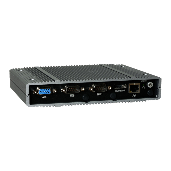
Page 12: Front And Rear Panels
Board Connector Cable Antenna Connector Washer Antenna Chassis Wall Note: It is highly unecessary at any point of the installation process that the I/O stand- offs and screws be removed from the front and rear panels. User's Manual | EC700-AL... -
Page 13: Ssd Tray
Screw in the four black screws provided in the package to secure the SSD in place. ble to the SSD and the board connectors. Note: After the SATA SSD is correctly mounte, please attach the bottom cover back on as previously instructed User's Manual | EC700-AL... -
Page 14: Board Layout
Power-off the PC then unplug the power cord prior to installing any devices. Failure to do so will cause severe damage to the motherboard and com- LAN3 (optional) LAN2 ponents. Reset & Status LED Mini PCIe 1 LAN1 User's Manual | EC700-AL... -
Page 15: System Memory
Data will be accessed in chunks of 64 bits from the memory channels. Retention Clip Socket Top View Features • 2G/4G/8G DDR3L Memory Down • One SO-DIMM Memory up to 8GB • Single Channel DDR3L 4 5 ° User's Manual | EC700-AL... -
Page 16: Jumper Settings
The jumper allows you to choose between system power-on via power button and automatic Inspect that the clip sits in the power-on via DC power in. notch. If not, please pull the clips outward, release and remove the Step 3 card, and mount it again. User's Manual | EC700-AL... -
Page 17: Front Panel (Jp1)
The COM3 / DIO port is a DB9 connector and can be used as a COM Serial port or a DIO port (8-bit GPIO). Both JP8 and JP9 shall be configured concurrently when switching between the two modes. User's Manual | EC700-AL... -
Page 18: Sw4
To load the default values stored in the ROM BIOS, please follow the steps below. 1. Power-off the system and unplug the power cord. 2. Press SW4 for a few seconds. 3. Plug the power cord back in and and power on the system. User's Manual | EC700-AL... -
Page 19: I/O Ports
The insertion is fairly effortless and please reframe from forcing BIOS Setting the insertion to prevent damage. Configure USB devices in the Advanced menu (“USB Configuration” submenu) of the BIOS. Re- fer to Chapter 7 for more information. User's Manual | EC700-AL... -
Page 20: Rj45 Lan Ports
Configure the COM ports including its communication mode in the Advanced menu (“Super IO • 2 or 4 x Intel I210IT PCIe (10/100/1000Mbps) ® Configuration” submenu) of the BIOS. Refer to Chapter 3 for more information. User's Manual | EC700-AL... -
Page 21: Dc-In
Calculating the system’s approximate power usage is important to ensure that the power supply meets the system’s consump- „ SATA 3.0 Pin Assignment „ SATA Power Pin Assignment tion requirements. User's Manual | EC700-AL... -
Page 22: Battery
• There exists explosion hazard if the battery is incorrectly installed. occurred, the alarm will sound only when the system restarts. • Replace only with the same or equivalent type recommended by the manufacturer. • Dispose of used batteries according to local ordinances. User's Manual | EC700-AL... -
Page 23: Expansion Slots
M.2 more suitable in application for solid-state storage. The board preserves space and a standoff for the M.2 E key socket (22mm x 30mm). The M.2 E key sup- ports PCIe and USB 2.0 signals. User's Manual | EC700-AL... -
Page 24: Installing Sim Card
The card should be lying paral- Step 3: Step 4: lel to the board when it’s correctly Orient the SIM card and place it into Close the cover and slide the cover mounted. the socket. to lock. User's Manual | EC700-AL... -
Page 25: Chapter 3 - Bios Settings
When “X” appears on the left of a particular field, it indicates that a submenu which contains additional options are available for that field. To display the submenu, move the highlight to that field and press <Enter>. User's Manual | EC700-AL... -
Page 26: Main
The time format is <hour>, <minute>, <second>. The time is based on the 24-hour military-time clock. For example, 1 p.m. is 13:00:00. Hour displays hours from 00 to 23. Minute displays min- utes from 00 to 59. Second displays seconds from 00 to 59. User's Manual | EC700-AL... -
Page 27: Acpi Configuration
Enable this field and manually set a temperature to which the CPU TDP adheres — increments from 80°C to 110°C. Note: Some of the fields may not be available when the features are not supported by the equipped CPU. User's Manual | EC700-AL... -
Page 28: Audio Configuration
SATA Port 0 Information about the mSATA (Mini PCIe 1) device. SATA Port 1 Information about the SATA SSD Drive device. Port 0/1 and Hot Plug Enable or disable the Serial ATA port and its hot plug function. User's Manual | EC700-AL... -
Page 29: Pci Express Configuration
PCIe Speed Select PCIe Speed of the current port — AUTO, Gen1, or Gen 2. Hot Plug Enable or disable hot plug function of the port. User's Manual | EC700-AL... -
Page 30: Sio Nuvoton6116D
Select parity bits: None, Even, Odd, Mark or Space. Stop Bits Select stop bits: 1 bit or 2 bits. Note: The sub-menus are detailed in following sections. Flow Control Select flow control type: None or Hardware RTS/CTS. User's Manual | EC700-AL... -
Page 31: Nct6116D Hw Monitor
This section displays the system’s health information, i.e. voltage readings, CPU and system temperature readings. Enable or disable the current serial COM port. COM1/2/3/4 Mode Select the serial mode for the COM ports — RS232, RS422, or RS485. User's Manual | EC700-AL... -
Page 32: Lan Configuration
Ipv4 PXE Support Enable or disable IPv4 PXE boot support. Ipv6 PXE Support Enable or disable IPv6 PXE boot support. Note: The number of LAN ports can be 2 or 4 according to your system SKU. User's Manual | EC700-AL... -
Page 33: Trusted Computing
Select the keyboard NumLock state — On or Off. Quiet Boot This section is used to enable or disable quiet boot option. SCC eMMC Support (D28:F0) Enable or disable the SCC eMMC. Boot Option Priorities Rearrange the system boot order of available boot devices. User's Manual | EC700-AL... -
Page 34: Save & Exit
Move the cursor to an available boot device and press Enter, and then the system will immedi- ately boot from the selected boot device. The Boot Override function will only be effective for the current boot. The “Boot Option Priorities” configured in the Boot menu will not be changed. User's Manual | EC700-AL...
Need help?
Do you have a question about the EC700-AL and is the answer not in the manual?
Questions and answers