Table of Contents
Advertisement
Quick Links
Advertisement
Table of Contents

Related Manuals for DFI RC300-CS


Summary of Contents for DFI RC300-CS
- Page 1 RC300-CS Railway Fan-less Box PC User’s Manual Preliminary RC300-CS www.dfi.com...
-
Page 2: Copyright
Product names or trademarks appearing in this manual are for identification purpose only and ance could void the user’s authority to operate the equipment. are the properties of the respective owners. Shielded interface cables must be used in order to comply with the emission limits. RC300-CS www.dfi.com... -
Page 3: Table Of Contents
Safety Measures .................4 Safety Precautions ................5 About the Package ................5 Chapter 1 - Introduction ..............6 Specifications ........................6 Getting to Know the RC300-CS ................8 Mechanical Dimensions ....................9 Chapter 2 - Getting Started ............10 Chapter 3 - Installing Devices ............11 Preface ..........................11 Devide the power parts ....................11... -
Page 4: About This Manual
About this Manual Static Electricity Precautions An electronic file of this manual can be obtained from the DFI website at www.dfi.com. To It is quite easy to inadvertently damage your PC, system board, components or devices even download the user’s manual from our website, please go to Support > Download Center. On before installing them in your system unit. -
Page 5: Safety Precautions
• Unplug the power cord before removing the system chassis cover for installation or servic- ing. After installation or servicing, cover the system chassis before plugging the power cord. • 1 RC300-CS system unit • Danger of explosion if battery incorrectly replaced. -
Page 6: Chapter 1 - Introduction
M.2 but also mPCIe slots. AUDIO Audio Codec Realtek ALC262 ETHERNET Controller 5 x Intel® I210IT NIC (10/100/1000Mbps) 1 x Intel® I219LM PHY (10/100/1000Mbps) Interface 2 x RJ45 GbE 4 x M12 X-coded 802.3af 15.4W PoE ports RC300-CS www.dfi.com... - Page 7 EN61373: 2010, Category 1 Class B tions Certifications CE, FCC Class B (Tested with Adapter) EMC: EN50121-3-2 Safety: EN50153, EN50124-1 Fire Proof: EN45545 Railway Regulation: EN50155 (Class S1: for RC300H-CS) IP Rating IP40 Country of Country of Taiwan Origin Origin RC300-CS www.dfi.com...
-
Page 8: Getting To Know The Rc300-Cs
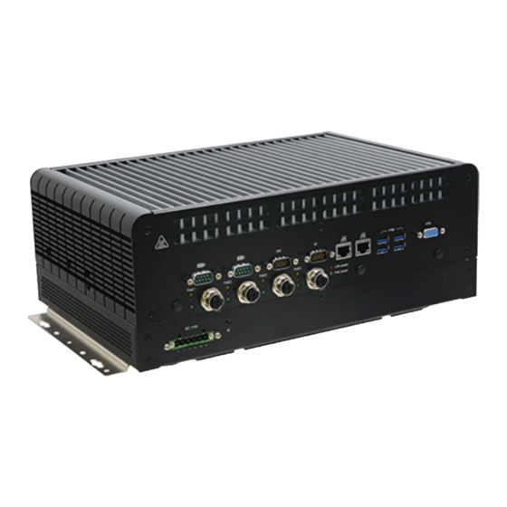
Chapter 1 Getting to Know the RC300-CS Front View Rear View GbE1~2 USB 3.0 VGA Power Button HDMI DP++ USB 2.0 DC-in 77~137V, M12 POE SSD 1~4 Line-out Mic-in 9~36V DC-in Jack Power Button Connects a DC-in power adapter. Please note the acceptable power range: 77-137V, 9~36V. -
Page 9: Mechanical Dimensions
Mechanical Dimensions RC300-CS www.dfi.com... -
Page 10: Chapter 2 - Getting Started
Installing the Operating System Make sure that a SATA drive is already installed. Refer to the following chapters for information on installing a SATA drive Refer to your operating system manual for instructions on installing an operating system. RC300-CS www.dfi.com... -
Page 11: Chapter 3 - Installing Devices
1. Turn over the machine to let the bottom side become the top. Preface RC300-CS is combined by two parts: Power part and main body. By devi- ding the power parts you can install so-dimm / m.2 / mini-PCIe modules. - Page 12 5. There’re two 2.5” hdd slots for harddisk/SSD installation. 5. If you want to change/remove/install other components, please re- 4. The power part appears. move the power part first.Remove the 4 screws in each corner circled by red. RC300-CS www.dfi.com...
- Page 13 6. Tilt up to remove the power part carefully and slowly. Please unplug 8. Remove each component by the screws circled in red. these cables first. 7. The main body appears. 9. The expansion slots appear. RC300-CS www.dfi.com...
-
Page 14: Pin Define Of M12 Poe
Pin Define of M12 PoE Assignment DC+ PoE DC+ PoE DC- PoE DC- PoE RC300-CS www.dfi.com... -
Page 15: X1 / X2 Slots For Canbus Or Mvb Connectors
On the back panel between SIM and SSD there are two slots for MVB or CANBus Connectors. Please use a solid metal screwdriver or plier to push the metal plates at- tached to remove them. Fix them on the back Connect plate. to internal ports. ST102-CS www.dfi.com... -
Page 16: Pin Define Of Di/Do
Pin Define of DI/DO Assignment Assignment Assignment Assignment GPI0_ISO GPO0_ISO GPI2_ISO GPI1_ISO GPO2_ISO GPO1_ISO ISO_POWER GPI3_ISO ISO_POWER GPO3_ISO GPI4_ISO GPI5_ISO GPO4_ISO GPO5_ISO GPI6_ISO GPI7_ISO GPO6_ISO GPO7_ISO GND_ISO GND_ISO RC300-CS www.dfi.com... -
Page 17: Pin Define Of Com1/2
5 9 4 8 3 7 2 5 9 4 8 3 7 2 Assignment Assignment Assignment Assignment MDCD1- MRTS1- MDCD2- MRTS2- MSIN1 MCTS1- MSIN2 MCTS2- MSOUT1 MRI1- MSOUT2 MRI2- MDTR1- AGND_COM MDTR2- AGND_COM AGND_COM AGND_COM MDSR1- MDSR2- RC300-CS www.dfi.com... - Page 18 12. Four slots follow the same procedure. metal marked in red to eject the buffle. 11. After the buffle has been ejected, you can insert or remove/replace the 2.5” storage devices by pulling or pushing them out/into the slots. RC300-CS www.dfi.com...
-
Page 19: Pin Define Of Dc110V
Pin Define of DC110V DC110V RC300-CS www.dfi.com... -
Page 20: Board Layout
M i n i P C I e 3 C a s e O p e n S O J 1 Power Button SYS_FAN M . 2 - M ( R 1 ) T S C N 2 12V_DC1 RC300-CS www.dfi.com... -
Page 21: Jumper Settings
SMBus Reset Reset Button Button Header Header CN37 CN37 Power Power Button SYS_FAN Button SYS_FAN 12V_DC1 12V_DC1 M.2 Socket Power M2JP2 Mini PCIe Power MPJP4 3V3 (default) 1-2 On 3V3SB (default) 1-2 On 3V3SB 2-3 On 2-3 On RC300-CS www.dfi.com... - Page 22 M2JP1 LAN1 Sim3 JP24 M2CN2 USB2_3/4 M.2-B MPCN5 MPCN3 USB3_3/4 Mini PCIe2 Mini PCIe1 SATA1(R3) USB2_1/2 CN38 USB3_1/2 12V_DC2 SATA0(R2) SMBus Reset Button Header CN37 Power Button SYS_FAN 12V_DC1 DIO Power ISJP5 5VSB (default) 1-2 On 2-3 On RC300-CS www.dfi.com...
- Page 23 Sim3 JP24 M2CN2 USB2_3/4 M.2-B MPCN5 MPCN3 USB3_3/4 Mini PCIe2 Mini PCIe1 SATA1(R3) USB2_1/2 CN38 USB3_1/2 12V_DC2 SATA0(R2) SMBus Reset Button Header CN37 Power Button SYS_FAN 12V_DC1 DI 4~7 Power ISJP3 DIO PWR (default) 1-2 On 2-3 On RC300-CS www.dfi.com...
- Page 24 Sim3 JP24 M2CN2 USB2_3/4 M.2-B MPCN5 MPCN3 USB3_3/4 Mini PCIe2 Mini PCIe1 SATA1(R3) USB2_1/2 CN38 USB3_1/2 12V_DC2 SATA0(R2) SMBus Reset Button Header CN37 Power Button SYS_FAN 12V_DC1 DI 0~3 Power ISJP4 DIO PWR (default) 1-2 On 2-3 On RC300-CS www.dfi.com...
- Page 25 SMBus Reset Reset Button Button Header Header CN37 CN37 Power Power Button SYS_FAN Button SYS_FAN 12V_DC1 12V_DC1 M.2 B KEY Power M2JP1 Mini PCIe1 Power MPJP2 3V3SB (default) 1-2 On 3V3SB (default) 1-2 On 2-3 On 2-3 On RC300-CS www.dfi.com...
- Page 26 LAN1 Sim3 JP24 M2CN2 USB2_3/4 M.2-B MPCN5 MPCN3 USB3_3/4 Mini PCIe2 Mini PCIe1 SATA1(R3) USB2_1/2 CN38 USB3_1/2 12V_DC2 SATA0(R2) SMBus Reset Button Header CN37 Power Button SYS_FAN 12V_DC1 Mini PCIe2 Power MPJP3 3V3SB (default) 1-2 On 2-3 On RC300-CS www.dfi.com...
-
Page 27: Internal Connectors
MDSR3- Sim1 MRTS3- LAN2 MCTS3- Sim2 MPJP3 MPJP2 M2JP1 LAN1 X_MRI3- Sim3 JP24 M2CN2 USB2_3/4 M.2-B MPCN5 MPCN3 USB3_3/4 Mini PCIe2 Mini PCIe1 SATA1(R3) USB2_1/2 CN38 USB3_1/2 12V_DC2 SATA0(R2) SMBus Reset Button Header CN37 Power Button SYS_FAN 12V_DC1 RC300-CS www.dfi.com... - Page 28 CN38 CN38 USB3_1/2 USB3_1/2 12V_DC2 12V_DC2 SATA0(R2) SATA0(R2) SMBus SMBus Reset Reset Button Button Header Header CN37 CN37 Power Power Button SYS_FAN Button SYS_FAN 12V_DC1 12V_DC1 Function Function X_MDCD4- +12V_SATA2 MSIN4 MSOUT4 MDTR4- 5V_SATA2 MDSR4- MRTS4- MCTS4- X_MRI4- RC300-CS www.dfi.com...
- Page 29 POE BTB Sim1 LAN2 Sim2 MPJP3 MPJP2 M2JP1 LAN1 Sim3 JP24 M2CN2 USB2_3/4 M.2-B MPCN3 MPCN5 USB3_3/4 Mini PCIe2 Mini PCIe1 SATA1(R3) USB2_1/2 CN38 USB3_1/2 12V_DC2 SATA0(R2) SMBus Reset Button Header CN37 Power Button SYS_FAN 12V_DC1 Function +12V_SATA2 5V_SATA2 RC300-CS www.dfi.com...
- Page 30 CN37 Power Power Power Power Button SYS_FAN Button Button Button SYS_FAN SYS_FAN SYS_FAN 12V_DC1 12V_DC1 12V_DC1 12V_DC1 Function Function Function Function Function LAD1 +12V_SATA1 +12V_SATA1 +12V_SATA1 RST# LAD0 FRAME# VCC3 LAD3 5V_SATA1 5V_SATA1 5V_SATA1 LAD2 N.C. SERIRQ 5VSB RC300-CS www.dfi.com...
- Page 31 Reset Reset Button Button Button Button Header Header Header Header CN37 CN37 CN37 CN37 Power Power Power Power Button Button SYS_FAN SYS_FAN Button Button SYS_FAN SYS_FAN 12V_DC1 12V_DC1 12V_DC1 12V_DC1 Function Function Function +12V_SATA1 +12V_SATA1 TACH 5V_SATA1 5V_SATA1 RC300-CS www.dfi.com...
- Page 32 M2B_WAKE# CLKOUT_mPCIE_P Button Button Header Header CN37 CN37 Power Power N.C. Button Button SYS_FAN SYS_FAN 12V_DC1 12V_DC1 N.C. N.C. N.C. N.C. N.C. N.C. Function Function N.C. N.C. 3V3_M2 M2B_SIM_DET M2B_RESET#_R 3V3_M2 N.C. 3V3_M2 M2B_CMC_USB2P 3V3_M2 M2B_CMC_USB2N M2B_LED# 3V3_M2 RC300-CS www.dfi.com...
- Page 33 12V_DC2 12V_DC2 SATA0(R2) SATA0(R2) SMBus SMBus Reset Reset N.C. 3V3_ Button Button Header Header CN37 CN37 Power Power Button Button SYS_FAN SYS_FAN 12V_DC1 12V_DC1 N.C. Function Function mPCIE_R_WAKE# N.C. N.C. N.C. SIM_PWR_ SIM_IO_ CLKOUT_mPCIE_N SIM_CLK_ CLKOUT_mPCIE_P SIM_RESET_ SIM_VPP_ RC300-CS www.dfi.com...
- Page 34 12V_DC2 12V_DC2 SATA0(R2) SATA0(R2) SMBus SMBus Reset Reset N.C. 3V3_MINI3 Button Button Header Header CN37 CN37 Power Power Button Button SYS_FAN SYS_FAN 12V_DC1 12V_DC1 N.C. Function Function mPCIE_3_R_WAKE# N.C. N.C. N.C. SIM_PWR_3 SIM_IO_3 CLKOUT_mPCIE_N3 SIM_CLK_3 CLKOUT_mPCIE_P3 SIM_RESET_3 SIM_VPP_3 RC300-CS www.dfi.com...
- Page 35 Mini PCIe1 SATA1(R3) SATA1(R3) USB2_1/2 USB2_1/2 CN38 CN38 USB3_1/2 USB3_1/2 12V_DC2 12V_DC2 SATA0(R2) SATA0(R2) SMBus SMBus Reset Reset Button Button Header Header CN37 CN37 Power Power Button Button SYS_FAN SYS_FAN 12V_DC1 12V_DC1 Function Function 3V3SB SMB_CLK_RESUME SMB_DATA_RESUME SMBALERT_PCH- RC300-CS www.dfi.com...
-
Page 36: Chapter 4 - Bios Setup
“Reset” button. You may also additional options are available for that field. To display the submenu, move the highlight to restart the system by pressing the <Ctrl> <Alt> and <Del> keys simultaneously. that field and press <Enter>. RC300-CS www.dfi.com... - Page 37 The time format is <hour>, <minute>, <second>. The time is based on the 24-hour military-time clock. For example, 1 p.m. is 13:00:00. Hour displays hours from 00 to 23. Minute displays minutes from 00 to 59. Second displays seconds from 00 to 59. RC300-CS www.dfi.com...
- Page 38 Press +/- to set the second from 0 to 59. Virtual Battery Enable or disable virtual battery, it’s for MXM RTX20xx and its above versions. If enabled, the system supports S4(Suspend to disk mode) if WIN10 PCH driver installed. RC300-CS www.dfi.com...
- Page 39 Threading, e.g. Windows and Linux. This field is not available when the equipped CPU does not support Hyper-threading. Enable or disable CPU Power Management. When enabled, the CPU is allowed to go to C states when it’s not 100% utilized. Configurable TDP Settings Configure PL1 and PL2 range. RC300-CS www.dfi.com...
- Page 40 This section is used to configure Intel(R) Active Management Technology Parameters. Please refer to the following pages. ME Unconfig on RTC Clear When disabled, ME will not be unconfigured on RTC Clear. ► Firmware Update Configuration Please refer to the following pages. RC300-CS www.dfi.com...
- Page 41 Enable or disable to hide unconfigure ME confirmation prompt when attempt- ing ME unconfiguration. Force Secure Erase Unconfigure ME Enable or disable Force Secure Erase on next boot. Enable or disable to unconfigure ME with resetting MEBx password to default. RC300-CS www.dfi.com...
- Page 42 F2: Previous Values F9: Optimized Defaults F10: Save & Exit ESC: Exit Version 2.20.1275. Copyright (C) 2021 American Megatrends, Inc. Me FW Image Re-Flash This field is used to enable or disable the Me FW Image Re-Flash function. RC300-CS www.dfi.com...
- Page 43 OS. TCG EFI protocol and INT1A interface will not be available. Pending operation Schedule an opeartion for the security device. Your computer will reboot during restart in order to change state of the security device. RC300-CS www.dfi.com...
- Page 44 Set SuperIO WatchDog Timer Timeout value. The range is from 0 (disabled) to 255. Determine the electrical interface mode. ► Serial Port 1/2/3/4 Configuration Configure the parameters of serial port 1 (COM 1) to serial port 4 (COM 4) as detailed later. RC300-CS www.dfi.com...
- Page 45 Fan Speed Count 1 field. Speed Count 1 to Speed Count 4 Set the fan speed, the value ranging from 1-100%, 100% being full speed. The fans will operate according to the specified boundary temperatures above- mentioned. RC300-CS www.dfi.com...
- Page 46 Data Bits Select data bits: 7 bits or 8 bits. Parity Select parity bits: None, Even, Odd, Mark or Space. Stop Bits Select stop bits: 1 bit or 2 bits. Flow Control Select flow control: None or Hardware RTS/CTS. RC300-CS www.dfi.com...
- Page 47 This field controls the execution of UEFI and Legacy Storage OpROM. Video This field controls the execution of UEFI and Legacy Video OpROM. Other PCI devices This field determines OpROM execution policy for devices other than Network, Storage or Video. RC300-CS www.dfi.com...
- Page 48 Set the wait time in seconds to press ESC key to abort the PXE boot. Use either +/- or numeric keys to set the value. Media detect count Set the number of times the presence of media will be checked. Use either +/- or numeric keys to set the value. RC300-CS www.dfi.com...
- Page 49 Version 2.20.1275. Copyright (C) 2021 American Megatrends, Inc. Primary Display Select a Graphics device to be the primary display — Auto, IGFX, SG Please choose SG for MXM vendor applications. (Switchable Graphics = Optimus) Internal Graphics Keep IGFX enabled based on the setup options. RC300-CS www.dfi.com...
- Page 50 Version 2.20.1275. Copyright (C) 2021 American Megatrends, Inc. Enable or disable integrated LAN to wake the system. Above 4GB MMIO BIOS assignment Switch MemoryMappedIO BIOS assignment above 4GB. Max TOLUD Assign a value or set “Dynamic” to automatically adjust TOLUD based on largest MMIO length. RC300-CS www.dfi.com...
- Page 51 Select the speed of the PCI Express root port: Auto, Gen1, Gen 2 or Gen3. This field will not appear when the root port does not support speed configuration. Hot Plug To enable or disable Hot Plug functions. RC300-CS www.dfi.com...
- Page 52 This field is only available when SATA Mode Selection is set to “Intel RST Pre- mium With Optane System Acceleration.” It is used to enable or disable to use RST Legacy OROM. Serial ATA Ports Enable or disable the Serial ATA port and its hot plug function. RC300-CS www.dfi.com...
- Page 53 Force System to User Mode and install factory default Secure Boot key data- bases. Return to Setup Mode This command is only available when the system mode is in User mode and Secure Boot Mode is set to Custom. RC300-CS www.dfi.com...
- Page 54 Select this option to save BIOS configuration settings to a USB flash device. Select the driver boot order. Restore Setting from file This field will appear only when a USB flash device is detected. Select this field to restore setting from the USB flash device. RC300-CS www.dfi.com...
- Page 55 You may refer to the how-to video “How the safety concerns, the BIOS (SPI ROM) chip cannot be removed from this system board and to update AMI BIOS in UEFI mode on DFI products?” at https://www.dfi.com/Knowledge/ used on another system board of the same model.
Need help?
Do you have a question about the RC300-CS and is the answer not in the manual?
Questions and answers