
Related Manuals for DFI EC90A-AL


Summary of Contents for DFI EC90A-AL
- Page 1 EC90A-AL Fanless Embedded System User’s Manual Preliminary Version A50000821 Chapter 1 Introduction...
- Page 2 Copyright FCC and DOC Statement on Class A This publication contains information that is protected by copyright. No part of it may be re- This equipment has been tested and found to comply with the limits for a Class B digital produced in any form or by any means or used to make any transformation/adaptation without device, pursuant to Part 15 of the FCC rules.
-
Page 3: Table Of Contents
Chapter 1 - Introduction ......6 Overview .................6 Key Features ................6 Specifications ................7 Getting to Know the EC90A-AL ..........8 Mechanical Dimensions ............9 Chapter 2 - Getting Started ...... 10 Chapter 3 - Installing Devices ....11 Removing the Chassis Cover ........... 11 Chapter 4 - Jumper Settings ..... -
Page 4: About This Manual
About this Manual Static Electricity Precautions An electronic file of this manual can be obtained from the DFI website at www.dfi.com. To It is quite easy to inadvertently damage your PC, system board, components or devices even download the user’s manual from our website, please go to Support > Download Center. On before installing them in your system unit. -
Page 5: Safety Precautions
• Unplug the power cord before removing the system chassis cover for installation or servic- ing. After installation or servicing, cover the system chassis before plugging the power cord. • One EC90A-AL system unit • One Quick Installation Guide • Danger of explosion if battery incorrectly replaced. -
Page 6: Chapter 1 - Introduction
Chapter 1 Chapter 1 - Introduction Overview Key Features Model Name EC90A-AL Processor Intel Atom ® Processor E3900 Series, BGA 1296 Two LAN ports COM/DIO One serial or digital input/output port: Front View RS-232/422/485 in DB9 connector Display One Mini DisplayPort Two USB 3.0 and one USB 2.0 Type A ports... -
Page 7: Specifications
Chapter 1 Specifications Processor Intel Atom ® Processor E3900 Series, BGA 1296 System ® Intel Atom x5-E3940 Processor, Quad Core, 2M Cache, 1.6GHz (1.8GHz), 9W ® Intel Atom x5-E3930 Processor, Dual Core, 2M Cache, 1.3GHz (1.8GHz), 6.5W Memory • 2GB/4GB Memory Down Dual Channel LPDDR4 2400MHz Graphics •... -
Page 8: Getting To Know The Ec90A-Al
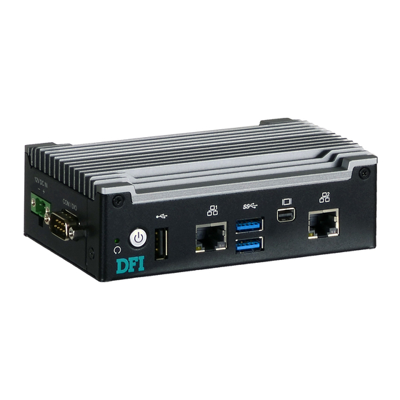
Chapter 1 Getting to Know the EC90A-AL Front View Side View Power Button with LED LAN 1 LAN 2 USB 3.0 DC-in COM / DIO ̶ + USB 2.0 Mini DP++ Reset Reset Button DC-in Connector Press to reset the system without disconnecting the system’s power. -
Page 9: Mechanical Dimensions
Chapter 1 Mechanical Dimensions Chassis Dimension 80.40 Left View Right View Top View Front View Chapter 1 Introduction... -
Page 10: Chapter 2 - Getting Started
Chapter 2 Chapter 2 - Getting Started Preparing the System Before you start using the system, you need the following items: • Power adapter (an optional item) or other means of power supply • Screwdriver Installing Devices The following devices can be installed in the system. •... -
Page 11: Chapter 3 - Installing Devices
Chapter 3 Chapter 3 - Installing Devices Lift the cover to open the system. The Mini PCIe socket is readily accessible after removing the chassis cover. Removing the Chassis Cover Please observe the following guidelines and follow the procedure to open the system. Make sure the system and all other peripheral devices connected to it have been powered off. - Page 12 Chapter 3 Installing a Mini PCIe Card The system board is equipped with one Mini PCIe slot that supports both PCIe and USB interfaces. Grasp the Mini PCIe card by its edges and align the notch in the connector of the PCIe card with the key in the connector on the system board.
-
Page 13: Chapter 4 - Jumper Settings
Chapter 4 Chapter 4 - Jumper Settings COM1/DIO Select If COM1 is configured as a serial port, its pin definition is as follows: RS232 RS422 Full Duplex RS485 TXD- DATA- TXD+ DATA+ RXD+ N.C. RXD- N.C. 10 7 N.C. N.C. N.C. -
Page 14: Chapter 5 - Ports And Connectors
Chapter 5 Chapter 5 - Ports and Connectors Panel I/O Ports USB 2.0 LAN 1 Reset USB 3.0 Mini DP LAN 2 COM1 12V DC-in The front panel I/O consists of the following ports: The left panel I/O consists of the following ports: •... -
Page 15: Rj45 Lan Ports
Chapter 5 RJ45 LAN Ports 12V DC-in LAN 2 LAN 1 Features • 2 Intel I210IT PCI Express Gigabit Ethernet controllers ® This 2-pin terminal block on the power board is considered a low power solution. It is an ex- ternal DC-in connector that accepts DC power and supplies power to the main board. -
Page 16: Usb Ports
Chapter 5 USB Ports Driver Installation You may need to install proper drivers in your operating system to use USB devices. Refer to Chapter 8 for more information. Wake-On-USB Keyboard/Mouse The Wake-On-USB Keyboard/Mouse function allows you to use a USB keyboard or USB mouse to wake up the system from the S3 (STR - Suspend To RAM) state. -
Page 17: Graphics Interface
Chapter 5 Graphics Interface Serial Port RS232/422/485 COM1 or 8-bit DIO MIni DP++ Port Mini DP++ Port Serial Port The Mini DP++ port is a digital display interface used to connect a display device such as COM 1 can be used for serial communication (RS232, RS422 or RS485) or 8-bit DIO via a computer monitor. -
Page 18: Internal I/O Connectors
Chapter 5 Internal I/O Connectors COM1 Function Pins RS422 Function Front Panel Connector (Internal) RS232 RS485 Full Duplex TXD- DATA- DIO0 TXD+ DATA+ DIO1 RXD+ N.C. DIO2 RXD- N.C. DIO3 Front Panel N.C. N.C. DIO6 N.C. N.C. DIO7 N.C. N.C. DIO4 N.C. -
Page 19: Expansion Slot
Chapter 5 Expansion Slot SMBus Connector SMBus Full-size Mni PCIe (PCIe x1/USB 2.0) Mini PCI Express Slot The System Management Bus (SMBus) connector (on the back side of the system board) is used to connect SMBus devices. It is a multiple device bus that allows multiple chips to con- The full-size Mini PCIe socket provides PCIe x1 and USB 2.0 signals and is used to install a nect to the same bus and enable each one to act as a master by initiating data transfer. -
Page 20: Battery
Chapter 5 Battery Battery +3.3V Connect to the battery connector Battery The lithium-ion battery powers the real-time clock and CMOS memory. It is an auxiliary source of power when the main power is shut off. Safety Measures • Danger of explosion if battery incorrectly replaced. •... -
Page 21: Chapter 6 - Mounting Options
Chapter 6 Chapter 6 - Mounting Options The following diagrams show the location and dimension of the wall moutning holes. Wall Mount The wall mount kit includes the following: • Two wall mount brackets • Bracket screws Align the mounting holes of the wall mount bracket with the screw holes of the system and use the provided mounting screws to secure the wall mount brackets on both sides of the system. - Page 22 Chapter 6 DIN rail Mount The system features DIN rail mount chassis that facilitates fast installation of the EC90A-AL to a DIN rail. The DIN rail mount kit includes the following: • DIN rail mount bracket • 2 screws Use the provided mounting screws to attach the DIN rail mount bracket to the rear side of the device.
-
Page 23: Chapter 7 - Bios Setup
Chapter 7 Chapter 7 - BIOS Setup Legends Overview Keys Function The BIOS is a program that takes care of the basic level of communication between the CPU Right and Left and peripherals. It contains codes for various advanced features found in this system board. Moves the highlight left or right to select a menu. - Page 24 Chapter 7 Insyde BIOS Setup Utility Advanced The Advanced menu allows you to configure your system for basic operation. Some entries are Main defaults required by the system board, while others, if enabled, will improve the performance of your system or let you set some features according to your preference. The Main menu is the first screen that you will see when you enter the BIOS Setup Utility.
- Page 25 Chapter 7 CPU Configuration ACPI Configuration This section configures the CPU. This section configures system ACPI parameters. EIST Wake on LAN Enable or disable WOL (wake-on-LAN) to wake the system through an Ethernet adapter. Enable or disable the Enhanced Intel SpeedStep Technology, which helps optimize ®...
- Page 26 Chapter 7 Video Configuration This section configures the video settings. Primary Display Select the primary display for the system from the following options: IGD: integrated graphics devices PCIe: PCIe graphics devices Integrated Graphics Device Enable or disable the integrated graphics device. Chapter 7 BIOS Setup...
- Page 27 Chapter 7 PCI Express Configuration This section configures the settings of PCI Express root ports. PCI Express Root Port PCI Express Root Port 3 Enable or disable this PCI Express root port. Controls the PCIe signal of LAN Port 1. PCI Express Root Port 4 Controls the PCIe signal of LAN Port 2.
- Page 28 Chapter 7 Console Redirection Console redirection lets you monitor and control the system from a remote station by re-direct- ing the host screen output through a serial port. Console Serial Redirect COM 1 Enable or disable the serial redirection function for COM1 port on the system and config- Enable or disable the console redirection function.
- Page 29 Chapter 7 Super I/O This section configures the system super I/O chip parameters. PC Health Status This section displays PC health status. COM Port 1 Enable or disable a serial port. Disable Disable this serial port. Enable Enable this serial port. It also shows the Base I/O address and the assigned interrupt number.
- Page 30 Chapter 7 Security This section configures the Trusted Platform Module (TPM) function. Set Supervisor Password Set the administrative password for entering the BIOS utility or upon the entering of the power-on self-test (POST) process. The length of the password must be greater than 1 character and less than or equal to 10 characters.
- Page 31 Chapter 7 Boot PXE Boot Capability Enable or disable Preboot eXecution Environment (PXE) boot through an Ethernet port. This function can only be enabled if the Network Stack support is enabled. USB Boot Enable this function to boot from a USB flash drive. Note: The BIOS supports only UEFI boot but not legacy.
- Page 32 Chapter 7 Exit Exit Saving Changes Select this field and press <Enter> to exit BIOS setup and save your changes. Load Optimal Defaults Select this field and press <Enter> to load the optimal defaults. Discard Changes Select this field and press <Enter>to exit the BIOS setup without saving your changes. Save Setting to file Select this option to save BIOS configuration settings to a USB drive.
- Page 33 Knowledge/Video/31 from the Knowledge Base of the DFI website. 2. The BIOS (SPI ROM) on this system board must be the original equipment from the factory and cannot be used to replace one which has been utilized on other system boards.
-
Page 34: Chapter 8 - Supported Software
The system requires you to install drivers for some devices to operate properly. Your product package may include a CD that contain drivers. You can also download the latest drivers from the DFI Download Center: http://www.dfi.com/DownloadCenter Once you are in the Download Center page, select your product or type the model name and click "Search"... - Page 35 1. Setup is ready to install ment for more installation tips the utility. Click “Next” to and then click “Next”. continue. 4. Click “Finish” to exit setup. 2. Read the license agreement and then click “Yes”. Chapter 8 Supported Software www.dfi.com...
- Page 36 2. Read the license agreement and then click “Yes”. 5. Click “Yes, I want to restart this computer now” and then click “Finish”. Restarting the system will allow the new software instal- lation to take effect. Chapter 8 Supported Software www.dfi.com...
- Page 37 2. Click “Yes, I want to restart my computer now” and then click “Fin- ish”. Restarting the system will allow the new software installation to take effect. 3. Select the program features you want to install and then click “Next”. Chapter 8 Supported Software www.dfi.com...
- Page 38 5. After the installation is complete, click “Finish” to exit setup. 2. Read the license agreement carefully. Click “I accept the terms in the License Agreement” if you agree with the terms in the agreement and then click “Next”. Chapter 8 Supported Software www.dfi.com...
- Page 39 3. Read the file information and then 5. Setup is now installing the driver. click “Next”. 6. Click “Finish” to exit setup. 4. Setup is ready to install the driver. Click “Next” to begin the installa- tion. Chapter 8 Supported Software www.dfi.com...
- Page 40 1. Select “I accept the terms in the License Agreement“ then click “Next.” 4. Click “Finish“ when the installation is complete. 2. The screen shows the com- ponents that will be installed. Click “Next” to continue. Chapter 8 Supported Software www.dfi.com...
Need help?
Do you have a question about the EC90A-AL and is the answer not in the manual?
Questions and answers