Table of Contents
Advertisement
Quick Links
Advertisement
Table of Contents

Related Manuals for DFI ST102-CS


Summary of Contents for DFI ST102-CS
- Page 1 ST102-CS Desktop Box PC User’s Manual ST102-CS www.dfi.com...
-
Page 2: Trademarks
Product names or trademarks appearing in this manual are for identification purpose only and ance could void the user’s authority to operate the equipment. are the properties of the respective owners. Shielded interface cables must be used in order to comply with the emission limits. ST102-CS www.dfi.com... -
Page 3: Table Of Contents
Overview ..........................8 Chipset ..........................48 Key Features ........................8 Security ..........................52 Specifications ........................9 Boot ...........................53 Getting to Know the ST102-CS .................10 Save & Exit ........................53 Mechanical Dimensions ....................11 Updating the BIOS ......................54 Motherboard Dimensions ...................11 Notice: BIOS SPI ROM ....................54 Chapter 2 - Getting Started ............10 Chapter 8 - Supported Software ..........55... -
Page 4: About This Manual
About this Manual Static Electricity Precautions An electronic file of this manual can be obtained from the DFI website at www.dfi.com. To It is quite easy to inadvertently damage your PC, system board, components or devices even download the user’s manual from our website, please go to Support > Download Center. On before installing them in your system unit. -
Page 5: About The Package
• Unplug the power cord before removing the system chassis cover for installation or servic- ing. After installation or servicing, cover the system chassis before plugging the power cord. • 1 ST102-CS system unit • 1 CPU cooler • Danger of explosion if battery incorrectly replaced. - Page 6 Adapter lockable DC Jack 5.5/2.5mm, 671-110006-100G AC/DC 256GB, mSATA SSD, SATA3, 3D TLC, PE: 3K cable length 1500mm, with DFI-JP PSE 512GB, mSATA SSD, SATA3, 3D TLC, PE: 3K Power 332-700010-201G Power Cord US 3pin 1830mm Length 1TB, mSATA SSD, SATA3, 3D TLC, PE: 3K...
-
Page 7: Before Using The System
• Memory module • Storage devices such as hard disk drive You will also need external system peripherals you intend to use which will normally include at least a keyboard, a mouse and a video display monitor. ST102-CS www.dfi.com... -
Page 8: Chapter 1 - Introduction
Chapter 1 Chapter 1 - Introduction Key Features Overview Model Name ST102-CS 8th/9th Generation Intel ® Core i7/i5/i3 processors Processor 2 LAN ports 1 HDMI, 2 DP Displays 2 USB 2.0 ports (front) 4 USB 3.0 ports (rear) Mic-in, Line-out... -
Page 9: Specifications
I211AT PCIe (10/100/1000Mbps) ® 1 x Intel I219V PCIe with iAMT11.0 (10/100/1000Mbps) Audio Realtek ALC888S-VD2-GR Power • Power type - DC-in External Power Adapter: DC output 12V 100W, Level 6 Cooling System 1 x System Fan 1 x CPU Fan ST102-CS www.dfi.com... -
Page 10: Getting To Know The St102-Cs
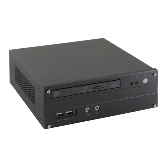
Chapter 1 Getting to Know the ST102-CS Front View Rear View Power Button DVD Drive DC-in Line-out HDMI DisplayPort LAN Ports USB 3.0 USB 2.0 HDD LED Mic-in USB 2.0 Power LED DVD RW Drive DC-in Jack A Slim Optical Disc Drive (ODD) for reading a disc. -
Page 11: Mechanical Dimensions
Chapter 1 Mechanical Dimensions Motherboard Dimensions Rear View 8.50 Right View Left View Front View ST102-CS www.dfi.com... -
Page 12: Chapter 2 - Getting Started
Refer to your operating system manual for instructions on installing an operating system. Installing the Drivers The system package includes a CD disk. The CD includes drivers that must be installed to pro- vide the best system performance. Refer to the Supported Software chapter for instructions on installing the drivers. ST102-CS www.dfi.com... -
Page 13: Chapter 3 - Installing Devices
Remove these screws and then put them in a safe place for later use. Mounting screw The SODIMM sockets and SATA drive bay are readily accessible after removing the chassis cover. SATA drive bay ODD drive bay ST102-CS www.dfi.com... - Page 14 Mounting screw HDD bracket Mounting screw Mounting screw Align the mounting holes on the SATA drive with the mounting holes on the HDD bracket. SATA mounting screws SATA mounting screws HDD bracket Mounting screw Mounting screw ST102-CS www.dfi.com...
-
Page 15: Installing A Memory Module
If installing only one memory module, please install it on the memory socket labeled DIMM 1 (the one closer to the center of the board). The SODIMM sockets can only accommodate DDR4 memory modules. Please do not install other types of memory modules. ST102-CS www.dfi.com... -
Page 16: Chapter 4 - Jumper Settings
2. Set the jumper pins 2 and 3 to On. Wait for a few seconds and set JP5 back to its default setting, pins 1 and 2 On. Note: 3. Now plug the power cord and power-on the system. Mini PCIe signal is only supported by Q370/C246. H310 only supports mSATA. ST102-CS www.dfi.com... -
Page 17: Panel Power Select
JP8 is used to select the power supplied with the LCD panel. Important: Before powering-on the system, make sure that the power settings of JP8 match the LCD panel’s specification. Selecting the incorrect voltage will seriously damage the LCD panel. ST102-CS www.dfi.com... -
Page 18: Lvds/Edp Signal Select
LVDS/eDP Signal Select ▲ 1-2 On: eDP JP10 ▲ 2-3 On: LVDS (default) JP10 is used to select the LVDS/eDP signal. ST102-CS www.dfi.com... -
Page 19: Chapter 5 - Ports And Connectors
• Audio Ports: • Ethernet Ports: Microphone & Line-out Two GbE (RJ-45) • Power and Status LED: • HDMI ports: HDD LED Status LED • Display ports: Note: Please gently press the power button to avoid possible damage. ST102-CS www.dfi.com... -
Page 20: Rj45 Lan Ports
Configure the onboard LAN ports in the Advanced menu (“ACPI Configuration” submenu) of the connector. BIOS. Refer to Chapter 7 - BIOS for more information. Driver Installation Install the LAN drivers. Refer to Chapter 8 - Supported Software for more information. ST102-CS www.dfi.com... -
Page 21: Graphics Interfaces
It is used to transmit audio and video simultaneously. The interface, which is developed by VESA, delivers higher performance features than any other digital interface. Driver Installation Install the graphics driver. Refer to Chapter 8 - Supported Software for more information. ST102-CS www.dfi.com... -
Page 22: Dc-In Jack
Configure the audio settings in the Advanced menu (“Audio Configuration” submenu) of the BIOS. Refer to Chapter 7 - BIOS for more information. Driver Installation Install the audio driver. Refer to Chapter 8 - Supported Software for more information. ST102-CS www.dfi.com... -
Page 23: I/O Connectors
ATA data cable to a SATA connector and the other end to your Serial ATA device. DIO5 DIO4 BIOS Setting DIO3 Configure the Serial ATA drives in the Advanced menu (“SATA Configuration” submenu) of the DIO2 BIOS. Refer to Chapter 7 - BIOS for more information. DIO1 DIO0 ST102-CS www.dfi.com... -
Page 24: Cooling Fan Connectors
PCB for a M.2 E Key module, and a 22x80mm socket and standoff for a M.2 M Key module. PCI Express x4 Slot Install PCI Express cards such as network cards or USB expansion cards that comply to the PCI Express specifications into the PCI Express x4 slot. ST102-CS www.dfi.com... -
Page 25: Chassis Intrusion Connector
On Suspend) state, it will blink every second. When the system is in the S3 (STR - Suspend To RAM) state, it will blink every 4 seconds. Pin Pin Assignment Pin Pin Assignment HDD Power LED Power HDD LED Signal PWR LED LED Power Ground Signal RST Signal Ground RESET SW ATX SW N.C. Signal ST102-CS www.dfi.com... -
Page 26: Smbus Connector
Safety Measures • Danger of explosion if battery incorrectly replaced. • Replace only with the same or equivalent type recommend by the manufacturer. • Dispose of used batteries according to local ordinance ST102-CS www.dfi.com... -
Page 27: Com (Serial) Ports
Make sure the colored stripe on the ribbon cable is aligned with pin 1 of the COM connector. BIOS Setting Configure the COM ports 1/2/3/4 in the Advanced menu (“NCT6116D Super IO Configuration” submenu) of the BIOS. Refer to the chapter 7 for more information. ST102-CS www.dfi.com... -
Page 28: Lvds Lcd Panel Connector
BIOS. Refer to the chapter 7 for more information. Panel Power Panel Power Note: LVDS LCD Panel Connector (DFI PN: 346-714000-204G) Description: WTB HEADER 40P, 1.25mm, M,H=4.8mm, 180D, SMT, BEIGE, 712-76-40GWE0(PRINEX) RoHS LCD/Inverter Power Connector (DFI PN: 3346-510801-100G) Description: BOX HEADER 1*8, 8P/2.0mm/180D, 721-81-08TW00(PINREX)RoHS ST102-CS www.dfi.com... -
Page 29: Chapter 6 - Mounting Options
The mounting holes are located at the side panel of the system. Fasten the mounting stand on the side of the system using the mounting screws. Mounting screws Place the system upright with the stand's support at the bottom. Desktop mounting stand ST102-CS www.dfi.com... -
Page 30: Chapter 7 - Bios Setup
“Reset” button. You may also additional options are available for that field. To display the submenu, move the highlight to restart the system by pressing the <Ctrl> <Alt> and <Del> keys simultaneously. that field and press <Enter>. ST102-CS www.dfi.com... -
Page 31: Aptio Bios Setup Utility
The time format is <hour>, <minute>, <second>. The time is based on the 24-hour military-time clock. For example, 1 p.m. is 13:00:00. Hour displays hours from 00 to 23. Minute displays minutes from 00 to 59. Second displays seconds from 00 to 59. ST102-CS www.dfi.com... - Page 32 Press +/- to set the minute from 0 to 59. what state the system is set to return to when power is re-applied after a power failure (G3 state). Wake up second Press +/- to set the second from 0 to 59. ST102-CS www.dfi.com...
- Page 33 Threading, e.g. Windows and Linux. This field is not available when the equipped CPU does not support Hyper-threading. Enable or disable CPU Power Management. When enabled, the CPU is allowed to go to C states when it’s not 100% utilized. ST102-CS www.dfi.com...
- Page 34 This section is used to configure Intel(R) Active Management Technology Parameters. Please refer to the following pages. ME Unconfig on RTC Clear When disabled, ME will not be unconfigured on RTC Clear. ► Firmware Update Configuration Please refer to the following pages. ST102-CS www.dfi.com...
- Page 35 Enable or disable to hide unconfigure ME confirmation prompt when attempt- ing ME unconfiguration. Force Secure Erase Unconfigure ME Enable or disable Force Secure Erase on next boot. Enable or disable to unconfigure ME with resetting MEBx password to default. ST102-CS www.dfi.com...
- Page 36 F2: Previous Values F9: Optimized Defaults F10: Save & Exit ESC: Exit Version 2.20.1271. Copyright (C) 2019 American Megatrends, Inc. Me FW Image Re-Flash This field is used to enable or disable the Me FW Image Re-Flash function. ST102-CS www.dfi.com...
- Page 37 Select the color depth of the LCD Panel — 18 Bit, 24 Bit, 36 Bit, 48 Bit. Backlight Type Enable or disable the serial ATA port and its hot plug function. Important: The configuration must match the specifications of your LCD Panel in order for the LCD Panel to display properly. ST102-CS www.dfi.com...
- Page 38 Set SuperIO WatchDog Timer Timeout value. The range is from 0 (disabled) to 255. Select a PCI Express root port and press “Enter” to configure. ► Serial Port 1/2/3/4 Configuration Configure the parameters of serial port 1 (COM 1) to serial port 4 (COM 4) as detailed later. ST102-CS www.dfi.com...
- Page 39 Fan Speed Count 1 field. Speed Count 1 to Speed Count 4 Set the fan speed, the value ranging from 1-100%, 100% being full speed. The fans will operate according to the specified boundary temperatures above- mentioned. ST102-CS www.dfi.com...
- Page 40 Version 2.20.1271. Copyright (C) 2019 American Megatrends, Inc. When “CPU Smart Fan Mode” is set to “Manual mode”, the following field will appear. Manual PWM Setting Set the fan speed to a fixed value, ranging from 1-100%, 100% being maximum speed. ST102-CS www.dfi.com...
- Page 41 Data Bits Select data bits: 7 bits or 8 bits. Parity Select parity bits: None, Even, Odd, Mark or Space. Stop Bits Select stop bits: 1 bit or 2 bits. Flow Control Select flow control: None or Hardware RTS/CTS. ST102-CS www.dfi.com...
- Page 42 This field controls the execution of UEFI and Legacy Storage OpROM. Video This field controls the execution of UEFI and Legacy Video OpROM. Other PCI devices This field determines OpROM execution policy for devices other than Network, Storage or Video. ST102-CS www.dfi.com...
- Page 43 Set the wait time in seconds to press ESC key to abort the PXE boot. Use either +/- or numeric keys to set the value. Media detect count Set the number of times the presence of media will be checked. Use either +/- or numeric keys to set the value. ST102-CS www.dfi.com...
-
Page 44: Chipset
F10: Save & Exit ESC: Exit Version 2.20.1271. Copyright (C) 2019 American Megatrends, Inc. Primary Display Select a Graphics device to be the primary display — Auto, IGFX, PEG, PCI. Internal Graphics Keep IGFX enabled based on the setup options. ST102-CS www.dfi.com... - Page 45 Please refer to the following pages. ► HD Audio Configuration Please refer to the following pages. LAN1(I219) Enable or disable onboard NIC. Wake on LAN Enable Version 2.20.1271. Copyright (C) 2019 American Megatrends, Inc. Enable or disable integrated LAN to wake the system. ST102-CS www.dfi.com...
- Page 46 This field is used to enable or disable the PCI express root port. PCIe Speed Select the speed of the PCI Express root port: Auto, Gen1, Gen 2 or Gen3. This field will not appear when the root port does not support speed configuration. ST102-CS www.dfi.com...
- Page 47 With Optane System Acceleration.” It is used to enable or disable to use RST Legacy OROM. Serial ATA Port 0/1/2/3 and Hot Plug Enable or disable the Serial ATA port and its hot plug function.RST Legacy OROM. ST102-CS www.dfi.com...
-
Page 48: Security
Force System to User Mode and install factory default Secure Boot key data- bases. Return to Setup Mode This command is only available when the system mode is in User mode and Secure Boot Mode is set to Custom. ST102-CS www.dfi.com... -
Page 49: Boot
Select this option to save BIOS configuration settings to a USB flash device. Select the driver boot order. Restore Setting from file This field will appear only when a USB flash device is detected. Select this field to restore setting from the USB flash device. ST102-CS www.dfi.com... -
Page 50: Updating The Bios
You may refer to the how-to video “How the safety concerns, the BIOS (SPI ROM) chip cannot be removed from this system board and to update AMI BIOS in UEFI mode on DFI products?” at https://www.dfi.com/Knowledge/ used on another system board of the same model. -
Page 51: Chapter 8 - Supported Software
CD that contain drivers. You can also download the latest drivers from the DFI Download Center: Please use the following procedure to install the “Intel Chipset Device Software”. - Page 52 1 to 2 minutes (while WinSAT is running) before the Windows 7/Windows 8.1/Windows 10 desktop appears. The “blank screen” period is the time Windows is testing the graphics performance. 2. Read the license agreement and then click “Yes”. ST102-CS www.dfi.com...
- Page 53 Restarting the system will allow the new software installation to take effect. 5. Click “Yes, I want to restart this computer now” and then click “Finish”. Restarting the system will allow the new software installation to take effect. ST102-CS www.dfi.com...
- Page 54 2. Read and License Agree- ment and click “I accept the terms in the license agreement” if you agree the terms in the agree- ment, and then click “Next”. 3. Select the program features you want to install and then click “Next”. ST102-CS www.dfi.com...
- Page 55 2. Read and License Agree- ment and click “I accept the terms in the license agreement” if you agree with the terms in the agreement, and then click “Next”. 5. After the installation is complete, click “Finish” to exit setup. ST102-CS www.dfi.com...
- Page 56 4. Setup is ready to install the driver. Click “Next” to begin the installa- tion. 2. Read the license agreement care- fully. Click “I accept the terms in the License Agreement” if you agree with the terms in the agreement and then click “Next”. ST102-CS www.dfi.com...
- Page 57 5. Setup is now installing the driver. 6. Click “Finish” to exit setup. ST102-CS www.dfi.com...
Need help?
Do you have a question about the ST102-CS and is the answer not in the manual?
Questions and answers