Advertisement
• 1 ST102-SD system unit
• Mounting screws for Mini PCIe modules
• Mounting screws for M.2 modules
• 1 Quick Installation Guide
• 1 CD disk includes:
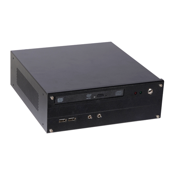
Front View
Rear View
DC-in
Notes:
The HDMI is a DP++/HDMI combo port but can only transmit HDMI signals (unless wired as a DP++ port).
Please plug in an HDMI cable with the right orientation and alignment to avoid damage to the connector.
You should feel resistance (due to a pin on the right) if the cable is not inserted correctly. Please see a video
at https://youtu.be/SUj07rfN5l8 for detailed instructions.
Aligning side
(left)
DFI reserves the right to change the specifications at any time prior to the product's release. For the latest revision and details of the
installation process, please refer to the user's manual.
ST102-SD Installation Guide
Package Contents
- Drivers / Manual
DVD Drive
USB 2.0
DVI-D
(DVI-I connector)
Angled-corner
pin
www.dfi.com
Panel
Line-out
Mic-in
HDMI
USB 3.0
Angled-corner
(up)
1
Power Button
HDD LED
Power LED
LAN Ports
Align this edge with the
left side of the connector
Advertisement
Table of Contents

Related Manuals for DFI ST102-SD


Summary of Contents for DFI ST102-SD
-
Page 1: Package Contents
(left) (up) DFI reserves the right to change the specifications at any time prior to the product's release. For the latest revision and details of the installation process, please refer to the user's manual. www.dfi.com... -
Page 2: Removing The Chassis Cover
Removing the Chassis Cover Installing internal components requires you to remove the chassis cover first. Please observe the following guidelines and follow the procedure to open the system. 1. Make sure the system and all other peripheral devices connected to it have been powered off. -
Page 3: Installing A Memory Module
Installing a Memory Module The system board is equipped with two memory slots. Please use the following procedure to install SODIMM modules. Grasp the module by its edges and align the memory’s notch with the socket’s notch; then insert the memory into the socket at an angle and push it down until you feel a click. -
Page 4: Installing A Sata Drive
Installing a SATA Drive The system can accommodate one 2.5” SATA drive. Please use the following procedure to install a 2.5” SATA drive. 1. Remove the 2 mounting screws that secure the drive bay to the system. Mounting screw HDD bracket Mounting screw 2. - Page 5 3. Use the mounting screws provided in the drive bay kit to attach the HDD bracket onto the drive bay and secure the drive in place. HDD bracket mounting screws HDD bracket mounting holes (on the drive bay’s bottom side) SATA mounting screws Mounting screw...
- Page 6 4. Place the SATA drive bay back in the chassis and install the SATA drive bay using the mounting screws you removed in step 1. SATA power/ data cable Mounting screw 5. Connect the SATA data/power cable to the SATA drive (refer to the above picture).
-
Page 7: Clear Cmos
LVDS LCD Panel COM 1 COM 2 COM 3 COM 4 Clear CMOS Data Auto Power-on Select Normal 1-2 On (default) Power-on via power button 1-2 On (default) Clear CMOS 2-3 On Power-on via AC Power 2-3 On www.dfi.com A52801917...
Need help?
Do you have a question about the ST102-SD and is the answer not in the manual?
Questions and answers