Table of Contents
Advertisement
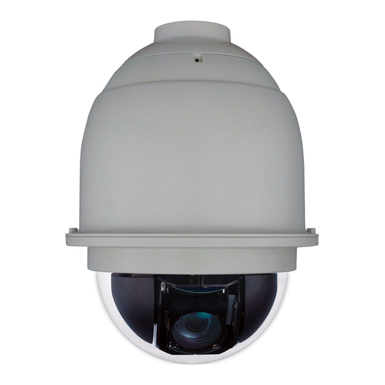
HDZ Series
Analogue PTZ Dome
HDZ30A
HDZ30AX
HDZ36AE
HDZ36AEX
User Manual
Recommended
Find the latest version of this and other HDZ Series PTZ dome camera
documents on the Honeywell Video website. Go to
http://www.honeywellvideo.com/products/cameras/pt/index.html
to find
your camera and view/download the latest documentation.
Document 800-16526 – Rev A – 07/2014
Advertisement
Table of Contents

Related Manuals for Honeywell HDZ30A


Summary of Contents for Honeywell HDZ30A
-
Page 1: User Manual
HDZ36AEX User Manual Recommended Find the latest version of this and other HDZ Series PTZ dome camera documents on the Honeywell Video website. Go to http://www.honeywellvideo.com/products/cameras/pt/index.html to find your camera and view/download the latest documentation. Document 800-16526 – Rev A – 07/2014... - Page 2 Revisions Issue Date Revisions 07/2014 New document.
-
Page 3: Cautions And Warnings
Cautions and Warnings RISK OF ELECTRIC SHOCK DO NOT OPEN CAUTION: TO REDUCE THE RISK OF ELECTRIC SHOCK, DO NOT REMOVE COVER (OR BACK). NO USER SERVICEABLE PARTS INSIDE. REFER SERVICING TO QUALIFIED SERVICE PERSONNEL. WARNING Installation and servicing should be performed only by qualified and experienced technicians to conform to all local codes and to maintain your warranty. -
Page 4: Safety Instructions
• Do not install indoor-rated models in outdoor locations. • Any wall or ceiling mounting of the product should follow the manufacturer’s instructions and use a mounting kit approved or recommended by the manufacturer. www.honeywell.com/security... -
Page 5: Warranty And Service
Honeywell will repair or replace, at its sole option, free of charge, any defective products returned prepaid. In the event you have a problem with any Honeywell product, please call Customer Service at 1.800.323.4576 for assistance or to request a Return Merchandise Authorization (RMA) number. - Page 6 6 | HDZ Series Analogue PTZ User Manual www.honeywell.com/security...
-
Page 7: Table Of Contents
Contents | 7 Contents About This Document ..........Overview of Contents. - Page 8 Exiting the Preset Menu ........67 www.honeywell.com/security...
- Page 9 Contents | 9 Setting Up a Preset Tour ........67 Selecting the Preset Tour Number .
- Page 10 Index ............109 www.honeywell.com/security...
- Page 11 Figures | 11 Figures Figure 1-1 Indoor PTZ Dome Camera Dimensions ......18 Figure 1-2 Outdoor PTZ Dome Camera Dimensions .
- Page 12 Figure D-1 In-Ceiling Bracket Dimensions ........105 www.honeywell.com/security...
- Page 13 Table 2-8 Honeywell Mounts and Adapters ........30 Table 3-1 OSD Item Descriptions .
- Page 14 14 | HDZ Series Analogue PTZ User Manual www.honeywell.com/security...
-
Page 15: About This Document
| 15 About This Document This document provides instructions for installing, configuring, and operating the HDZ Series Analogue PTZ dome camera. This document is intended for system installers, administrators, and operators. Overview of Contents This document contains the following chapters and appendixes: •... -
Page 16: Related Documents
Buttons you click to perform actions Click Exit to close the program. Italic Placeholders: words that vary depending on the Enter your user name. situation Cross-reference to external source Refer to the System Administrator Guide. Cross-reference within document Chapter 2, Installation. www.honeywell.com/security... -
Page 17: Introduction
Dimensions, page 18 Overview The Honeywell HDZ Series True Day/Night Analogue PTZ dome camera is a high resolution PTZ series camera designed for use in a wide range of video surveillance applications. This guide is intended for use with the following HDZ Series cameras: •... -
Page 18: Dimensions
4 alarm inputs, 2 alarm outputs • Electronic image stabilizer • Auto exposure • Digital slow shutter • Electronic shutter Dimensions The indoor and outdoor HDZ Series cameras have the following dimensions: Figure 1-1 Indoor PTZ Dome Camera Dimensions 7.5" (191.5 mm) www.honeywell.com/security... -
Page 19: Upgrading Analogue Ptz Dome Firmware
Upgrading the firmware on the HDZ Series Analogue PTZ Dome is typically a complicated procedure. If a firmware upgrade for your camera at a site is needed, contact Honeywell technical support at 1.800.323.4576 (North America only). Refer to the back cover of this manual for international contact information. - Page 20 20 | HDZ Series Analogue PTZ User Manual www.honeywell.com/security...
-
Page 21: Installing The Camera
Before you begin, check that you have received all of the parts listed below. If any parts are missing or damaged, contact your dealer immediately. HDZ Series Indoor Dome Honeywell logo label M4 standard Lubricant UTP Balun DIP Switch tool... -
Page 22: Accessories You Can Order Separately
Dip Switches and Cable Connections on page 25). Finish mounting the camera (see Mounting the Camera on page 30). Configure the camera with the connected keyboard/controller (refer to Chapter 4, Operation and Configuration, page 51, for detailed instructions on configuring the camera settings). www.honeywell.com/security... -
Page 23: Assembling The Camera
Installing the Camera | 23 Assembling the Camera Camera assembly is quick and easy. To assemble the camera: Take the camera and all other components out of the packaging. Rotate and remove the protective cover bag from the camera body. Use the torx driver to remove the dome cover. -
Page 24: System Configuration
However, a repeater may also be needed when the network distance is less than 1.2 km if the cables used are not CAT 5, 24-gauge cables. www.honeywell.com/security... -
Page 25: Dip Switches And Cable Connections
Installing the Camera | 25 Dip Switches and Cable Connections Before connecting the cables, take a minute to familiarize yourself with the camera’s back plate connectors, switches, and buttons, as shown in Figure 2-2 Table 2-2 below. Figure 2-2 Camera Back Plate Layout HDZ Indoor Dome Cameras HDZ Outdoor Dome Cameras Table 2-2... -
Page 26: Setting Dip Switches
Appendix C, ID Settings page Figure 2-4 ID Setting Dip Switches Note No two cameras in a network should be given the same camera ID. A communication conflict may occur. Table 2-3 ID Switch Settings Switch Setting SW10 www.honeywell.com/security... -
Page 27: Camera Control Protocol Setting
Installing the Camera | 27 Table 2-3 ID Switch Settings (cont’d) Switch Setting SW10 Camera Control Protocol Setting Define the protocol you are going to use on the devices of your surveillance system, based on the devices and protocols available. It is recommended to use one protocol on all devices, even with devices provided by different manufacturers. -
Page 28: Connecting Rs485
Connecting RS485 Refer to Figure 2-6 Table 2-5 when connecting a keyboard/controller to your camera through the RS485 connection. Honeywell UltraKey Touch (HJC4000) is recommended for use with the HDZ Analogue PTZ dome. Figure 2-6 RS485 Connector Table 2-5 RS485 Pin Definitions Definition R–... -
Page 29: Connecting Power
Installing the Camera | 29 Connecting Power WARNING To comply with EN50130-4 requirements, a UPS should be employed when powering the camera. Refer to Figure 2-7 Table 2-6 for the power connector definition before wiring power to the camera. CAUTION Check the pin definition of the power connector listed here before connecting to the power source. -
Page 30: Mounting The Camera
Corner Mount Adapter for HDXWM2 HDXPMA2 Pole Mount Adapter for HDXWM2 Note An In-ceiling mounting bracket (HDZINBKT) is available. Check with your Honeywell supplier regarding In-ceiling mounting. See Appendix D, In-Ceiling Bracket Installation, for in-ceiling bracket mounting instructions. For additional information, see Related Documents on page www.honeywell.com/security... -
Page 31: Using Safety Cable During Installation
Installing the Camera | 31 Using Safety Cable During Installation The HDZ Series PTZ camera includes an eyelet for attaching a safety cable to securely fix the camera to the mounting structure (see Figure 2-9). It is recommended that you install a safety cable (such as a 3/32-in. -
Page 32: Installing A Ceiling Mount (Indoor Only)
Check that the eyelet safety cable connection is secure, and carrying all of the load of the camera after making all cable connections. Attach the camera to the mount kit and then tightly fix the security screw on the top of the camera. www.honeywell.com/security... -
Page 33: Installing A Wall Mount
Installing the Camera | 33 Installing a Wall Mount The HDXWM2 wall mount weighs 3.2 lb. (1.45 kg) and can be installed directly to a load-bearing wall, or to a corner or pole using an appropriate adapter. The mount has a maximum load rating of 25.8 lb. -
Page 34: Installing A Parapet/Flat Roof Mount
Check that the eyelet safety cable connection is secure, and carrying all of the load of the camera after making all cable connections. Attach the camera to the mount kit and then tightly fix the security screw on the top of the camera. www.honeywell.com/security... -
Page 35: Understanding The Osd
After you have installed the PTZ dome, you are ready to begin configuring the dome settings from the OSD menu. You will need a keyboard controller and a monitor to do this. The HDZ Series Analogue PTZ Dome is compatible with Honeywell controllers: •... -
Page 36: Accessing The Main Menu
Figure 3-2. Please enter the password, select ENTER and press IRIS+ to access the OSD main menu. Figure 3-2 Enter Password Screen PLEASE ENTER PASSWORD _ _ _ _ 0123456789 DELETE ENTER EXIT www.honeywell.com/security... -
Page 37: Navigating Osd Menus
Understanding the OSD | 37 Note When first time turning the Password Function on, please enter the Master Password to setup the new password. Master Password: 9527. Navigating OSD Menus To select the setup item, use the joystick or direction keys on the keyboard to move the OSD cursor in the OSD menu. -
Page 38: Figure 3-3 Osd Display Elements
Year / Month / Day Hour : Minute XX: Facing direction of the PTZ including N, E, S, W, NE, NW, Position XX YYY / YY SE, SW Display YYY / YY: Angle of PTZ, 0 ~ 359 / 10 ~ –90 www.honeywell.com/security... -
Page 39: Osd Menu Tree
Understanding the OSD | 39 OSD Menu Tree The HDZ Series Analogue PTZ camera has an OSD menu to be used for setting up the camera options and features (presets, privacy masks, and so on). The main OSD menu is split into 3 pages that you can scroll through after opening the OSD menu (see Accessing the Main Menu on page... -
Page 40: Figure 3-5 Main Page 2 Osd Menus
Autopan Autopan Line Start Point End Point Direction Speed Run Autopan Delete Exit Mimic Tour Mimic Tour No. Record Start Record End Run Cruise Delete Exit Home Setting Home Function Select Mode Preset Point/Preset Tour/Autopan/Mimic Tour Return Time Exit www.honeywell.com/security... -
Page 41: Figure 3-6 Main Page 3 Osd Menus
Understanding the OSD | 41 Figure 3-6 Main Page 3 OSD Menus IR Function (Auto) IR Function (Manual) Threshold IR Manual Exit+Save Exit+Save Alarm Setting Alarm Pin Alarm Switch Main Page 3 Alarm Type IR Function Alarm Action Preset Point/Preset Tour/Autopan/Mimic Tour Alarm Setting Dwell Time Alarm Priority... -
Page 42: Osd Menu Structure
IRIS VALUE: F1.6 ~ F28 AE MODE AUTO IRIS EXIT+SAVE: YES BRIGHTNESS: AUTO SHUTTER SPEED PAL: 1/50 ~ 1/10000 SEC. NTSC: 1/60 ~ 1/10000 SEC. MANUAL IRIS VALUE: F1.6 ~ F28 GAIN VALUE: -3dB ~ 28dB EXIT+SAVE: YES EXIT+SAVE www.honeywell.com/security... - Page 43 Understanding the OSD | 43 Table 3-2 OSD Menu Structure (cont’d) Item Layer 1 Layer 2 Layer 3 Default AUTO (Auto White Balance) INDOOR OUTDOOR ATW (Auto-tracing WBC) WBC MODE R GAIN 000 ~ 127 MANUAL B GAIN 000 ~ 127 EXIT+SAVE: YES ZOOM SPEED MAX.
- Page 44 01 ~ 16 Press ENTER to create a title for the zone PRESET POINT 001 ~ 256 PRESET SET PT MOVE, TO SAVE PT MOVE PRESET RUN ENTER ENTER PRESET SET TITLE ENTER ENTER CLEAR TITLE ENTER ENTER EXIT ENTER www.honeywell.com/security...
- Page 45 Understanding the OSD | 45 Table 3-2 OSD Menu Structure (cont’d) Item Layer 1 Layer 2 Layer 3 Default PRESET TOUR NO. 1 ~ 16 PRESET NO. 01 ~ 32 PRESET POS. 001 ~ 255, END SPEED 01 ~ 15 PRESET TOUR DWELL TIME 000 ~ 127 SEC.
- Page 46 DETECT SWITCH ON, OFF DETECT MODE MOTION BLOCK MODE MOTION: ON, OFF MOTION DETECT FRAME SET MOTION: 1 ~ 4 FRAME SET 1-4 FRAME DISABLE MOTION: 1 ~ 4 THRESHOLD NONE, MOTION: 001 ~ 255 EXIT WDR FUNCTION ON, OFF www.honeywell.com/security...
- Page 47 Understanding the OSD | 47 Table 3-2 OSD Menu Structure (cont’d) Item Layer 1 Layer 2 Layer 3 Default PRIVACY SWITCH ON, OFF TRANSPARENCY ON, OFF BLACK, WHITE, RED, GREEN, BLUE, CYAN, YELLOW, COLOR BLACK MAGENTA, MOSAIC 1-3 H CENTER: L/R V CENTER: D/U PRIVACY MASK SET MASK...
-
Page 48: Basic Keyboard Controls
(displays: Broadcast RX Mode OFF) Opens Setup Menu 1 with the password field selected Run mimic tour 1–16 Program mimic tour MAXPRO-mode, VCL, Pelco P, Pelco D Run preset tour 1–16 Diamond, MAXPRO-mode, VCL, Pelco P, User default setting preset Pelco D www.honeywell.com/security... -
Page 49: Upgrading Analogue Ptz Firmware
Upgrading the firmware on the HDZ Series Analogue PTZ Dome is typically a complicated procedure. If a firmware upgrade for your camera at a site is needed, contact Honeywell technical support at 1.800.323.4576 (North America only) for assistance. Refer to the back cover of this manual for international contact information. - Page 50 50 | HDZ Series Analogue PTZ User Manual www.honeywell.com/security...
-
Page 51: Operation And Configuration
Operation and Configuration To operate and configure the HDZ Series Analogue PTZ dome camera, you will require a keyboard controller and monitor to connect to the PTZ dome. See System Configuration on page 24 for an overview of the devices to connect to the HDZ Series PTZ dome. Accessing the Main Menu on page 36 for information about opening the HDZ Series PTZ analogue dome OSD menus. -
Page 52: Setting The Language
There are three options available for the AF Mode, including NORMAL mode, Zoom Trigger (Z. TRIG.) mode and PTZ Trigger (PTZ TRIG) mode. The submenu of AF Mode is shown in Figure 4-2. Figure 4-2 Auto Focus Mode AF MODE NORMAL → EXIT+SAVE www.honeywell.com/security... -
Page 53: Manual Focus
Operation and Configuration | 53 Normal Mode In this mode, the camera will keep in focus automatically and continuously in any condition. Zoom Trigger Mode In this mode, auto focusing is activated at the time when the zoom value is changed. The camera will still auto focus once at the beginning of pan/tilt movement (no auto focusing during pan/tilt movement or when pan/tilt movement stops). -
Page 54: Exiting Ae Mode Sub Menu
Kelvin (K). You can select one of the White Balance Control modes according to this condition. The following table shows the color temperature of some general light sources. Table 4-1 Color Temperatures by Light Source Light Sources Color Temperature in K Cloudy Sky 6,000 to 8,000 Noon Sun and Clear Sky 6,500 www.honeywell.com/security... -
Page 55: Setting Auto Wbc
Operation and Configuration | 55 Table 4-1 Color Temperatures by Light Source (cont’d) Light Sources Color Temperature in K Household Lighting 2,500 to 3,000 75-watt Bulb 2,820 Candle Flame 1,200 to 1,500 Setting Auto WBC In this mode, white balance works within its color temperature range. This mode computes the white balance value output using color information from the entire screen. -
Page 56: Setup Menu Page 1 Settings
On the other hand, Digital zoom takes a portion of an image and expands the partial image to the full size of the original image; therefore, the image quality will be reduced. The Digital Zoom ratio is adjustable from 2x to 12x. The default setting is OFF. www.honeywell.com/security... -
Page 57: Setting The Slow Shutter
Operation and Configuration | 57 Setting the Slow Shutter The shutter speed setting determines how long the image sensor is exposed to light. To see a clear image in a dark environment, it is recommended you enable the Digital Slow Shutter function and select a slower shutter speed. -
Page 58: Enabling The Freeze Option
If the image stabilizer function is turned on, it will also set the WDR function to OFF, Digital Slow Shutter to no function and will limit the Digital Zoom capability. Exiting the Setup Menu 1 Exit the SETUP MENU 1 and go back to the MAIN PAGE 1 to continue setting other camera functions. www.honeywell.com/security... -
Page 59: Setup Menu Page 2 Settings
Operation and Configuration | 59 Setup Menu Page 2 Settings In Setup Menu 2 (see Figure 4-8), users can set the Flip, Angle Adjuster and PT Position settings, and choose whether to activate optional functions, including Speed by Zoom, Auto Calibration, Password, OSD Auto Closing and System Reset. -
Page 60: Mechanical Flip)
190 DEG → EXIT+SET Setting the PT Position PT Position can display the Pan/Tilt position of the Analogue PTZ Dome on the screen. See On-Screen Display Overview on page 37 for the on-screen location the PT position is displayed. www.honeywell.com/security... -
Page 61: Setting Pt Display
Operation and Configuration | 61 Figure 4-11 PT Position Options PT POSITION PT DISPLAY → SET PAN ZERO PT MOVE ↓ EXIT+SET Setting PT Display Turn this item to ON to display the pan/tilt position on the screen. The display format will be PXXX, TYY. -
Page 62: Using The Osd Password To Login
IRIS+ to access the OSD main menu. Figure 4-13 Enter Password Screen PLEASE ENTER PASSWORD _ _ _ _ 0123456789 DELETE ENTER EXIT Note When the Password Function on, please enter the Master Passport if the manually entered password has been forgotten. Master Password: 9527. www.honeywell.com/security... -
Page 63: Setting The Osd To Close Automatically
Operation and Configuration | 63 Setting the OSD to Close Automatically Users can specify the duration for OSD menu to stay open before automatically closing after a period of inactivity. Time selection ranges from 10 to 30 seconds. To keep the OSD menu on the screen until manually exited, set this option to OFF. -
Page 64: Setting The Id Display
Use the pan, tilt and zoom controls to operate the camera and move it to view the area (zone) that you want to set the title for. Turn on the OSD, and press the joystick or direction key down to go to MAIN PAGE 2. www.honeywell.com/security... -
Page 65: Setting Up A Preset Position
Operation and Configuration | 65 Select the ZONE TITLE option. Select a number to represent the current viewing area (zone). Press the IRIS+ key (ENTER) on the keyboard to open the title editing page (see Figure 4-15) Figure 4-15 Camera Title Editing ZONE TITLE: 01 0 1 2 3 4 5 6 7 8 9 EXIT... -
Page 66: Running A Programmed Preset
To delete a character, move the cursor to the LEFT or RIGHT command and press IRIS+ until you have selected a character in the entry field to be deleted. Select DELETE and press IRIS+ to delete the selected character. www.honeywell.com/security... -
Page 67: Deleting A Preset Title
Operation and Configuration | 67 When the title is complete, move the cursor to SAVE and press IRIS+. The new title will now display when viewing the preset it was set for. Deleting a Preset Title To delete the title for a preset point, select the preset to delete the title of in the PRESET POINT field, then move the cursor to CLEAR TITLE and press IRIS+. -
Page 68: Setting The Preset Position
IRIS+ key (ENTER) to execute the selected Preset Tour (see Selecting the Preset Tour Number on page 67 for more information). Note Users can also execute the Preset Tour function through a keyboard/controller. Please refer to the keyboard’s documentation for more information about executing PTZ commands. www.honeywell.com/security... -
Page 69: Deleting A Preset Tour
Operation and Configuration | 69 Deleting a Preset Tour Users can command the HDZ Series Analogue PTZ Dome to delete the selected Preset Tour. Move the cursor to DELETE and press the IRIS+ key (ENTER) to delete the selected Preset Tour (see Selecting the Preset Tour Number on page 67 for more information on selecting the... -
Page 70: Setting The Autopan Direction
Users can command the HDZ Series Analogue PTZ Dome to delete the selected Autopan Line. Move the cursor to DELETE and press the IRIS+ key (ENTER) to delete the selected Autopan Line (see Selecting an Autopan Line on page 69 for more information on selecting the Autopan to be deleted). www.honeywell.com/security... -
Page 71: Exiting The Autopan Menu
Operation and Configuration | 71 Exiting the Autopan Menu Exit the AUTOPAN setup menu and go back to the MAIN PAGE 2 to carry on setup of the camera. Setting Up a Mimic Tour A Mimic Tour is a route formulated by manual operation of the HDZ Series Analogue PTZ Dome. The user runs through a path by adjusting pan, tilt and zoom parameters, which will be stored by the camera and can be recalled to execute at any time. -
Page 72: Running A Mimic Tour
The HOME function allows constant and accurate monitoring to avoid the Analogue PTZ Dome idling or missing events. Figure 4-22 Home Setting Menu HOME SETTING HOME FUNCTION → SELECT MODE PRESET → PRESET POINT → RETURN TIME 001MIN → ENTER ↓ EXIT www.honeywell.com/security... -
Page 73: Enabling The Home Function
Operation and Configuration | 73 Enabling the Home Function This option is used to enable or disable the HOME function. Use the joystick or LEFT/RIGHT direction keys to change the setting. Selecting the Home Setting Mode Select the type of action that the HDZ Series Analogue PTZ Dome should execute when the HOME function is enabled and the RETURN TIME expires. -
Page 74: Setting The Return Time
During the day time, the IR cut filter will be on to block the infrared light for a clear image. During the night time, the IR cut filter will be removed to let the camera catch infrared light, and the displayed images will become black and white. www.honeywell.com/security... -
Page 75: Setting Auto Ir Function
Operation and Configuration | 75 Setting Auto IR Function With the Auto IR Function, the Internal circuit will automatically decide the occasion to remove the IR cut filter according to the value of light condition, as calculated by the internal light algorithm. -
Page 76: Enabling/Disabling The Alarm Switch
The preset point(s) should be setup in the PRESET setup menu or through the keyboard prior to using with the Alarm function (see Setting Up a Preset Position on page 65 for more information on setting up preset points). www.honeywell.com/security... -
Page 77: Setting The Dwell Time
Operation and Configuration | 77 Selecting a Preset Tour PRESET TOUR (P. TOUR) must be selected as the ALARM ACTION for this option to be available (see Selecting the Alarm Action on page 76). Select a preset tour that the Analogue PTZ Dome should execute when the selected alarm is triggered. -
Page 78: Configuring The Alarm Output
In Motion Detect mode, users can set Block Mode as ON or OFF. When BLOCK MODE is turned on, if there are any variations (caused by intrusion, for example) in the sections of the monitoring image, the affected parts will be dynamically highlighted. www.honeywell.com/security... -
Page 79: Setting The Motion Frame
Operation and Configuration | 79 Setting the Motion Frame In a monitored field, users can define specific areas as motion detection target zones. Up to four frames can be set as motion detection target zones. Please refer to the instructions as follows to configure parameters for each motion detection zone, called a Frame. -
Page 80: Disabling A Frame
WDR function. Enabling WDR Activate the WDR function by selecting ON for this option. In this mode, the HDZ Series Analogue PTZ Dome will operate the WDR function automatically. www.honeywell.com/security... -
Page 81: Disabling Wdr
Operation and Configuration | 81 Disabling WDR Deactivate the WDR function by selecting this OFF for this option. Setting Up Privacy Masks The Privacy Mask function aims to block any intrusive monitoring. Users can adjust the camera view position by moving the camera with the joystick, and adjust the mask size and area with the direction keys on the control keyboard. -
Page 82: Setting Up The Mask
Exit the Mask Menu and go back to the Privacy Mask menu to continue setting the privacy mask options. Clearing a Mask Users can delete a preset mask zone with this option. Please follow the steps below: Select the mask zone that will be erased (01, for example). Press IRIS+ to confirm the selection. www.honeywell.com/security... -
Page 83: Exiting The Privacy Mask Menu
Operation and Configuration | 83 Exiting the Privacy Mask Menu Exit the PRIVACY MASK menu and go back to the MAIN PAGE 3 to carry on setting up other camera settings. Setting Up the Time The time setting menu (see Figure 4-30) is used to set the time related options for the HDZ Series Analogue PTZ dome. -
Page 84: Enabling/Disabling Schedules
Users can select PRESET TOUR mode to assign a preset tour to the schedule point. A preset tour number must also be selected when this mode is selected. The preset tour must be previously configured to be available to select (see Setting Up a Preset Tour on page 67). www.honeywell.com/security... -
Page 85: Reseting A Schedule
Operation and Configuration | 85 AUTOPAN Users can select AUTOPAN mode to assign an autopan path to the schedule point. A autopan number must also be selected when this mode is selected. The autopan path must be previously configured to be available to select (see Setting Up an Autopan Path on page 69). - Page 86 86 | HDZ Series Analogue PTZ User Manual www.honeywell.com/security...
-
Page 87: Appendix A Hdz Camera Specifications
HDZ Camera Specifications Table A-1 HDZ30A(X) Series Camera Specifications Specification Description Camera Specifications Scanning System NTSC / PAL Image Sensor 1/4" Sony 960H CCD Optical Zoom Digital Zoom 1–12x variable Effective Pixels NTSC: 480K; PAL: 570K Horizontal Resolution 650 TVL Video Output 1.0 Vp-p @ 75 ohms (BNC) - Page 88 88 | HDZ Series Analogue PTZ User Manual Table A-1 HDZ30A(X) Series Camera Specifications (cont’d) Specification Description Operation Specifications (cont’d) Preset Speed 5° to 400°/s Preset Tour 16 tours with up to 32 presets per tour Auto Pan Mimic Tour...
-
Page 89: Table A-2 Hdz36Ae(X) Series Camera Specifications
HDZ Camera Specifications | 89 Table A-1 HDZ30A(X) Series Camera Specifications (cont’d) Specification Description Regulatory Emissions EN55022, FCC Part 15B Immunity EN50130-4 NA: UL/CSA 60950-1 Safety EU: EN60950-1 RoHS EN50581 Protecting the dome from direct sunlight in high temperature environments is advised. - Page 90 Outdoor (with sunshield): ø 7.5" x 10.7" (ø 191.5 mm x 270.5 mm) Weight 5.73 lb (2.6 kg), with sunshield Operating Temperature –40°F to 122°F (–40°C to 50°C) Relative Humidity 10% to 90%, non-condensing Waterproof Standard IP66 standard and NEMA 4X (HDZ Outdoor) www.honeywell.com/security...
- Page 91 HDZ Camera Specifications | 91 Table A-2 HDZ36AE(X) Series Camera Specifications (cont’d) Specification Description General Specifications (con’t) Power Source 24 V AC ± 10% Power Consumption 50 W (with Heater) Regulatory Emissions CE EN55022, FCC Part 15B Immunity CE EN50130-4 NA: UL/CSA 60950-1, UL/CSA 60950-22 Safety EU: EN60950-1, EN60950-22...
- Page 92 92 | HDZ Series Analogue PTZ User Manual www.honeywell.com/security...
-
Page 93: Appendix B Troubleshooting
Analogue PTZ Dome. Technical Support Prior to calling Honeywell technical support, refer to the following topics for possible solutions to problems with your HDZ Series Analogue PTZ Dome. To contact the Honeywell Video Systems technical support team, call 1-800-323-4576 (North America only) or fill out the form at https://www.honeywellsystems.com/ss/techsupp/index.html... -
Page 94: Problem: Communication Between Dome And Keyboard
Problem: Communication Between Dome and Keyboard To control the PTZ dome, users will need to connect the dome to a keyboard/controller (such as Honeywell’s HJC4000). If you are having problems with the communication between the dome and controller, check the following:... -
Page 95: Table B-1 Recommended Wdr And Dnr Settings By Scene Type
Troubleshooting | 95 Table B-1 Recommended WDR and DNR Settings by Scene Type (cont’d) Analogue HDZ Setting Day/Night Type of Scene Remark Mode 2D NR 3D NR Outdoor night time, with street lighting Color, B/W (Default setting) Turn on 3D NR for better static object identification in darkness, Outdoor night time, with dim lighting but a trail might be seen behind... - Page 96 96 | HDZ Series Analogue PTZ User Manual www.honeywell.com/security...
-
Page 97: Appendix C Id Settings
ID Settings This appendix covers all of the possible ID settings that can be set for the HDZ Series Analogue PTZ Dome (see Table C-1). Table C-1 ID Switch Settings Switch Setting SW10 800-16526 - A - 07/2014... - Page 98 98 | HDZ Series Analogue PTZ User Manual Table C-1 ID Switch Settings (cont’d) Switch Setting SW10 www.honeywell.com/security...
- Page 99 ID Settings | 99 Table C-1 ID Switch Settings (cont’d) Switch Setting SW10 800-16526 - A - 07/2014...
- Page 100 100 | HDZ Series Analogue PTZ User Manual Table C-1 ID Switch Settings (cont’d) Switch Setting SW10 www.honeywell.com/security...
- Page 101 ID Settings | 101 Table C-1 ID Switch Settings (cont’d) Switch Setting SW10 800-16526 - A - 07/2014...
- Page 102 102 | HDZ Series Analogue PTZ User Manual Table C-1 ID Switch Settings (cont’d) Switch Setting SW10 www.honeywell.com/security...
- Page 103 ID Settings | 103 Table C-1 ID Switch Settings (cont’d) Switch Setting SW10 800-16526 - A - 07/2014...
- Page 104 104 | HDZ Series Analogue PTZ User Manual www.honeywell.com/security...
-
Page 105: Appendix D In-Ceiling Bracket Installation
In-Ceiling Bracket Installation This document describes how to install an HDZ Series camera in a suspended ceiling using the HDZINBKT in-ceiling bracket. CAUTION Installation and servicing should be performed only by qualified and experienced technicians to conform to all local codes and to maintain your warranty. -
Page 106: Package Contents
Ceiling Support Plate, Honeywell Part Number 517082-7130 (not supplied) Installing the In-Ceiling Bracket It is recommended that you use a ceiling support plate (Honeywell part number 517082-7130) when installing the HDZINBKT in-ceiling bracket in a suspended ceiling. Step 1: Cut a hole in the ceiling Select the location where you want to install the camera. - Page 107 In-Ceiling Bracket Installation | 107 Do one of the following: Installation with Ceiling Support Plate Installation without Ceiling Support Plate Remove the ceiling tile at the selected Place the supplied ceiling template on the location and fit the ceiling tile inside ceiling at the selected location and cut the ceiling support plate.
- Page 108 Attach the trim ring to the ceiling support ring by lining up the two magnets on the trim ring with the two thumb screws on the ceiling support ring. Note No screws are needed to attach the trim ring. www.honeywell.com/security...
-
Page 109: Index
| 109 Index password preset point alarm output preset tour alarm settings privacy masks angle adjuster PT position aperture schedules auto calibration slow shutter auto exposure speed by zoom auto focus system reset autopan time settings WBC mode WDR function zone title backlight compensation zoom speed... - Page 110 OSD menu PT position regulatory statements alarm setup related documents angle adjuster setup resetting system aperture setup roof mount auto calibration setup auto close setup auto exposure setup autopan setup safety instructions backlight compensation setup schedules basic controls securing camera www.honeywell.com/security...
- Page 111 | 111 setup menu page 1 setup menu page 2 upgrading firmware slow shutter special presets specifications speed by zoom wall mount warnings warranty white balance control technical support wide dynamic range time settings title, zone zoom speed 800-16526 - A - 07/2014...
- Page 112 112 | HDZ Series Analogue PTZ User Manual www.honeywell.com/security...
-
Page 114: Document 800-16526 – Rev A
Document 800-16526 – Rev A – 07/2014 © 2014 Honeywell International Inc. All rights reserved. No part of this publication may be reproduced by any means without written permission from Honeywell. The information in this publication is believed to be accurate in all respects. However, Honeywell cannot assume responsibility for any consequences resulting from the use thereof.
Need help?
Do you have a question about the HDZ30A and is the answer not in the manual?
Questions and answers