
Related Manuals for FLIR ThermaCAM P65 HS


Summary of Contents for FLIR ThermaCAM P65 HS
- Page 1 99 Washington Street Melrose, MA 02176 Phone 781-665-1400 Toll Free 1-800-517-8431 Visit us at www.TestEquipmentDepot.com ThermaCAM™ P65 HS User’s manual Publ. No. 1558240 Rev. a156 – ENGLISH (EN) – March 1, 2006...
- Page 2 FLIR Systems or this warranty will not apply. FLIR Systems will, at its option, repair or replace any such defective product free of charge if, upon inspection, it proves to be defective in material or workmanship and provided that it is returned to FLIR Systems within the said one-year period.
- Page 3 Designation Status Reg. No. Germany Patent 60004227.8 Great Britain Design Patent 106017 Great Britain Design Patent 3006596 Great Britain Design Patent 3006597 Great Britain Patent 1188086 International Design Patent DM/057692 International Design Patent DM/061609 Japan Application 2000-620406 Japan Application 2002-588123 Japan Application 2002-588070...
- Page 4 Designation Status Reg. No. U.S. Pending 29/233,400 Publ. No. 1558240 Rev. a156 – ENGLISH (EN) – March 1, 2006 Test Equipment Depot - 800.517.8431 - 99 Washington Street Melrose, MA 02176 FAX 781.665.0780 - TestEquipmentDepot.com...
-
Page 5: Table Of Contents
Table of contents Warnings & cautions ........................Important note about this manual ....................Welcome! ............................About FLIR Systems ......................3.1.1 A few images from our facilities ................Comments & questions ......................Packing list ............................System overview ..........................Connecting system components .................... - Page 6 7.7.2 Rain showers ......................7.7.3 Emissivity ......................7.7.4 Reflected apparent temperature ................7.7.5 Object too far away ....................Tutorials ............................Switching on & switching off the camera ................Working with images & folders ..................... 8.2.1 Acquiring an image ....................8.2.2 Opening an image ....................
- Page 7 Keypad buttons & functions ....................Autofocus ..........................IrDA infrared communication link ..................Camera status LCD ......................Laser LocatIR ........................Visual camera ........................10 Camera program ..........................10.1 Screen objects ........................10.1.1 Result table ......................10.1.2 Status bar ......................10.1.3 Temperature scale ....................10.1.4 System messages ....................
- Page 8 10.2.5.6 Bluetooth® ..................10.2.5.7 Power ....................10.2.5.8 Status bar ..................10.2.5.9 Buttons ....................10.2.5.10 Date/time ................... 10.2.5.11 Local settings ..................10.2.5.12 Camera info ..................10.2.5.13 Profile ....................10.2.5.14 Factory default ................... 11 Folder and file structure ....................... 12 Electrical power system ......................... 12.1 Internal battery charging ......................
- Page 9 18.1 Introduction .......................... 18.2 Emissivity ..........................18.2.1 Finding the emissivity of a sample ............... 18.2.1.1 Step 1: Determining reflected apparent temperature ....... 18.2.1.2 Step 2: Determining the emissivity ........... 18.3 Reflected apparent temperature ..................18.4 Distance ..........................18.5 Relative humidity ........................18.6 Other parameters ........................
- Page 10 Publ. No. 1558240 Rev. a156 – ENGLISH (EN) – March 1, 2006 Test Equipment Depot - 800.517.8431 - 99 Washington Street Melrose, MA 02176 FAX 781.665.0780 - TestEquipmentDepot.com...
-
Page 11: Warnings & Cautions
Each camera from FLIR Systems is calibrated prior to shipping. It is advisable that ■ the camera is sent in for calibration once a year. - Page 12 1 – Warnings & cautions harmful interference in a residential installation.This equipment generates, uses and can radiate radio frequency energy and, if not installed and used in accordance with the instructions, may cause harmful interference to radio communications. However, there is no guarantee that interference will not occur in a particular instal- lation.
-
Page 13: Important Note About This Manual
Important note about this manual As far as it is practically possible, FLIR Systems configures each manual to reflect each customer’s particular camera configuration. However, please note the following exceptions: The packing list is subject to specific customer configuration and may contain more ■... - Page 14 2 – Important note about this manual INTENTIONALLY LEFT BLANK Publ. No. 1558240 Rev. a156 – ENGLISH (EN) – March 1, 2006...
-
Page 15: Welcome
The images can be analyzed either in the field by using the real- time measurement markers built into the camera software, or in a PC by using FLIR Systems's software for infrared analysis and reporting. -
Page 16: About Flir Systems
Figure 3.2 Indigo Operations, Niceville, USA, and Indigo Operations, Santa Barbara, USA. Indigo Operations is a division of FLIR Systems. As pioneers in the IR industry, FLIR Systems has a long list of ‘firsts’ the world of in- frared thermography: 1965: 1st thermal imaging system for predictive maintenance (Model 650). - Page 17 10 L (2.6 US gallon) jar with liquid nitrogen. To the left of the oscilloscope the Polaroid attachment (6 kg/13 lb) can be seen. RIGHT: FLIR Systems ThermaCAM Model E2 from 2002 – weight: 0.7 kg (1.54 lb), including battery.
-
Page 18: A Few Images From Our Facilities
3 – Welcome! 3.1.1 A few images from our facilities 10401303;a1 Figure 3.4 LEFT: Development of system electronics; RIGHT: Testing of an FPA detector 10401403;a1 Figure 3.5 LEFT: Diamond turning machine; RIGHT: Lens polishing Publ. No. 1558240 Rev. a156 – ENGLISH (EN) – March 1, 2006... - Page 19 3 – Welcome! 10401503;a1 Figure 3.6 LEFT: Testing of IR cameras in the climatic chamber; RIGHT: Robot for camera testing and calibration Publ. No. 1558240 Rev. a156 – ENGLISH (EN) – March 1, 2006...
-
Page 20: Comments & Questions
3 – Welcome! Comments & questions FLIR Systems is committed to a policy of continuous development, and although we have tested and verified the information in this manual to the best of our ability, you may find that features and specifications have changed since the time of printing. -
Page 21: Packing List
The ThermaCAM™ P65 HS and its accessories are delivered in a hard transport case which typically contains the items below. On receipt of the transport case, inspect all items and check them against the delivery note. Any damaged items must be reported to the local FLIR Systems representative immediately. Description Part number 4"... - Page 22 4 – Packing list INTENTIONALLY LEFT BLANK Publ. No. 1558240 Rev. a156 – ENGLISH (EN) – March 1, 2006...
-
Page 23: System Overview
System overview This system overview shows all accessories that are possible to order for a Therma- CAM™ P65 HS. 10570903;a3 Figure 5.1 System overview Publ. No. 1558240 Rev. a156 – ENGLISH (EN) – March 1, 2006... - Page 24 5 – System overview Figure 5.2 Explanations of callouts Callout Part No. Description of part 194 560 Protective plastic window 1 194 977 Protective window 194 579 124 mm IR lens 194 176 72 mm IR lens 194 401 18 mm IR lens 194 702 9.0 mm IR lens 194 533...
- Page 25 5 – System overview Callout Part No. Description of part One of the following Headset with Bluetooth® wireless technology part numbers: ➲ Depending on your camera configuration, this 1 910 218 feature may be an extra option. ■ 1 910 219 ■...
- Page 26 5 – System overview INTENTIONALLY LEFT BLANK Publ. No. 1558240 Rev. a156 – ENGLISH (EN) – March 1, 2006...
-
Page 27: Connecting System Components
Connecting system components Front connectors 10569403;a2 Figure 6.1 How to connect system components: Front connectors Figure 6.2 Explanations of callouts Callout Explanation USB or RS-232 cable. The connector on the camera is also used as a connector for the video lamp. Bluetooth®... -
Page 28: Rear Connectors
6 – Connecting system components Rear connectors 10438603;a2 Figure 6.3 How to connect system components: Rear connectors Figure 6.4 Explanations of callouts Callout Explanation FireWire cable CompactFlash card Power supply cable CVBS cable (i.e. composite video) Remote control cable Publ. No. 1558240 Rev. a156 – ENGLISH (EN) – March 1, 2006... -
Page 29: Finding The Ip Address For Cameras Connected Via Firewire: Method 1
6 – Connecting system components Finding the IP address for cameras connected via FireWire: Method 1 Step Action On the camera, look for the serial number and write it down. The address for the camera is ircamXXXXX, where XXXXX are the five last figures in the serial number. -
Page 30: Finding The Ip Address For Cameras Connected Via Firewire: Method
6 – Connecting system components Finding the IP address for cameras connected via FireWire: Method 2 Step Action In the command window, type ipconfig. This will typically display two networks – the camera network and the PC network: 10415703;a1 Look for the Default Gateway number for Connection specific DNS suffix: IN- FRARED and write it down. -
Page 31: Introduction To Thermographic Inspections Of Electrical Installations
Introduction to thermographic inspections of electrical installations Important note All camera functions and features that are described in this section may not be sup- ported by your particular camera configuration. Electrical regulations differ from country to country. For that reason, the electrical procedures described in this section may not be the standard of procedure in your particular country. -
Page 32: General Equipment Data
7 – Introduction to thermographic inspections of electrical installations and for the climatic zones. The measurement periods may also differ depending on the type of plant to be inspected, whether they are hydroelectric, nuclear, coal-based or oil-based plants. In the industry the inspections are—at least in Nordic countries with clear seasonal differences—carried out during spring or autumn or before longer stops in the oper- ation. -
Page 33: Inspection
7 – Introduction to thermographic inspections of electrical installations The more the IR camera operator knows about the equipment that he or she is about to inspect, the higher the quality of the inspection. But it is virtually impossible for an IR thermographer to have detailed knowledge about all the different types of equipment that can be controlled. -
Page 34: Priority
7 – Introduction to thermographic inspections of electrical installations The classification of the defects gives a more detailed meaning that not only takes into account the situation at the time of inspection (which is certainly of great impor- tance), but also the possibility to normalize the over-temperature to standard load and ambient temperature conditions. -
Page 35: Control
7 – Introduction to thermographic inspections of electrical installations However, the most common result of the identification and classification of the detected faults is a recommendation to repair immediately or as soon as it is practically possible. It is important that the repair crew is aware of the physical principles for the identifica- tion of defects. -
Page 36: Measurement Technique For Thermographic Inspection Of Electrical Installations
7 – Introduction to thermographic inspections of electrical installations Measurement technique for thermographic inspection of electrical installations 7.3.1 How to correctly set the equipment A thermal image may show high temperature variations: 10712803;a4 Figure 7.2 Temperature variations in a fusebox In the images above, the fuse to the right has a maximum temperature of +61°C (+142°F), whereas the one to the left is maximum +32°C (+90°F) and the one in the middle somewhere in between. - Page 37 7 – Introduction to thermographic inspections of electrical installations to be in for the moment. It might be so that you measure heat, which has been con- ducted over some distance, whereas the ‘real’ hot spot is hidden from you. An example is shown in the image below.
-
Page 38: Comparative Measurement
7 – Introduction to thermographic inspections of electrical installations 7.3.3 Comparative measurement For thermographic inspections of electrical installations a special method is used, which is based on comparison of different objects, so-called measurement with a reference. This simply means that you compare the three phases with each other. This method needs systematic scanning of the three phases in parallel in order to assess whether a point differs from the normal temperature pattern. -
Page 39: Normal Operating Temperature
7 – Introduction to thermographic inspections of electrical installations 10713303;a4 Figure 7.7 A profile (line) in an infrared image and a graph displaying the increasing temperature 7.3.4 Normal operating temperature Temperature measurement with thermography usually gives the absolute temperature of the object. In order to correctly assess whether the component is too hot, it is necessary to know its operating temperature, that is, its normal temperature if we consider the load and the temperature of its environment. -
Page 40: Classification Of Faults
7 – Introduction to thermographic inspections of electrical installations 10713503;a4 Figure 7.9 An infrared image of indoor electrical equipment (2) The two left phases are considered as normal, whereas the right phase shows a very clear excess temperature. Actually, the operating temperature of the left phase is +68°C (+154°F), that is, quite a substantial temperature, whereas the faulty phase to the right shows a temperature of +86°C (+187°F). - Page 41 7 – Introduction to thermographic inspections of electrical installations < 5°C (9°F) The start of the overheat condi- tion. This must be carefully monitored. 5–30°C (9–54°F) Developed overheating. It must be repaired as soon as possible (but think about the load situa- tion before a decision is made).
-
Page 42: Reporting
The program, which has been used for creating the report page shown below, is called ThermaCAM™ Reporter. It is adapted to several types of infrared cameras from FLIR Systems. A professional report is often divided into two sections: Front pages, with facts about the inspection, such as: ■... - Page 43 7 – Introduction to thermographic inspections of electrical installations 10713603;a3 Figure 7.10 A report example Publ. No. 1558240 Rev. a156 – ENGLISH (EN) – March 1, 2006...
-
Page 44: Different Types Of Hot Spots In Electrical Installations
7 – Introduction to thermographic inspections of electrical installations Different types of hot spots in electrical installations 7.5.1 Reflections The thermographic camera sees any radiation that enters the lens, not only originating from the object that you are looking at, but also radiation that comes from other sources and has been reflected by the target. -
Page 45: Inductive Heating
7 – Introduction to thermographic inspections of electrical installations 10713803;a3 Figure 7.12 An infrared image of a circuit breaker 7.5.3 Inductive heating 10713903;a3 Figure 7.13 An infrared image of hot stabilizing weights Eddy currents can cause a hot spot in the current path. In cases of very high currents and close proximity of other metals, this has in some cases caused serious fires. -
Page 46: Varying Cooling Conditions
7 – Introduction to thermographic inspections of electrical installations 10714003;a3 Figure 7.14 Examples of infrared images of load variations The image to the left shows three cables next to each other. They are so far apart that they can be regarded as thermally insulated from each other. The one in the middle is colder than the others. -
Page 47: Resistance Variations
7 – Introduction to thermographic inspections of electrical installations 7.5.6 Resistance variations Overheating can have many origins. Some common reasons are described below. Low contact pressure can occur when mounting a joint, or through wear of the mate- rial, for example, decreasing spring tension, worn threads in nuts and bolts, even too much force applied at mounting. - Page 48 7 – Introduction to thermographic inspections of electrical installations 10714303;a3 Figure 7.17 Overheating in a circuit breaker The overheating of this circuit breaker is most probably caused by bad contact in the near finger of the contactor. Thus, the far finger carries more current and gets hotter. The component in the infrared image and in the photo is not the same, however, it is similar).
-
Page 49: Disturbance Factors At Thermographic Inspection Of Electrical Installations
7 – Introduction to thermographic inspections of electrical installations Disturbance factors at thermographic inspection of electrical installations During thermographic inspections of different types of electrical installations, distur- bance factors such as wind, distance to object, rain or snow often influence the measurement result. -
Page 50: Distance To Object
7 – Introduction to thermographic inspections of electrical installations snow or rain and reliable measurement is no longer possible. This is mainly because a heavy snowfall as well as heavy rain is impenetrable to infrared radiation and it is rather the temperature of the snowflakes or raindrops that will be measured. 7.6.3 Distance to object This image is taken from a helicopter 20 meters (66 ft.) away from this faulty connec-... -
Page 51: Object Size
The reason for this effect is that there is a smallest object size, which gives correct temperature measurement. This smallest size is indicated to the user in all FLIR Sys- tems cameras. The image below shows what you see in the viewfinder of camera model 695. - Page 52 7 – Introduction to thermographic inspections of electrical installations 10714703;a3 Figure 7.21 Image from the viewfinder of a ThermaCAM 695 This effect is due to imperfections in the optics and to the size of the detector elements. It is typical for all infrared cameras and can not be avoided. Publ.
-
Page 53: Practical Advice For The Thermographer
7 – Introduction to thermographic inspections of electrical installations Practical advice for the thermographer Working in a practical way with a camera, you will discover small things that make your job easier. Here are ten of them to start with. 7.7.1 From cold to hot You have been out with the camera at +5°C (+41°F). -
Page 54: Reflected Apparent Temperature
7 – Introduction to thermographic inspections of electrical installations 7.7.4 Reflected apparent temperature You are in a measurement situation where there are several hot sources that influence your measurement. You need to have the right value for the reflected apparent tem- perature to input into the camera and thus get the best possible correction. -
Page 55: Tutorials
Tutorials Switching on & switching off the camera Step Action Insert a battery into the battery compartment. For information about inserting a battery, see section 8.8.6 – Inserting & removing the battery on page 61. Briefly press the green ON/OFF button to switch on the camera. Press and hold down the green on/off button for a few seconds to switch off the camera. -
Page 56: Working With Images & Folders
8 – Tutorials Working with images & folders 8.2.1 Acquiring an image Step Action Briefly press the green ON/OFF button to switch on the camera. Point the camera at a warm object, like a face or a hand. Press and hold down the A button for one second to adjust the focus. Briefly press the A button to autoadjust the camera. -
Page 57: Navigating In Folders
8 – Tutorials Step Action Do one of the following: To go to the external CompactFlash™ card, select the CompactFlash™ card ■ symbol and press the joystick. To go to the internal camera memory, select the camera symbol and press the ■... -
Page 58: Freezing & Unfreezing An Image
8 – Tutorials 8.2.7 Freezing & unfreezing an image Step Action Press and hold down the A button for one second to adjust the focus. Briefly press the A button to autoadjust the camera. Briefly press the S button to freeze the image. To unfreeze the image, press the S button once again. -
Page 59: Laying Out & Moving A Circle
8 – Tutorials Step Action Point to Add box on the Analysis menu and press the joystick. A box will now appear on the screen. The measured temperature will be displayed in the result table in the top right corner of the screen. You are now in edit mode and can move the box in any direction by pressing and moving the joystick. -
Page 60: Resizing A Measurement Marker
8 – Tutorials Step Action Point to Add isotherm on the Analysis menu and press the joystick. An isotherm will now be added to your image. The isotherm levels will be displayed in the result table in the top right corner of the screen. You are now in edit mode and can change the isotherm levels by moving the joy- stick up/down. - Page 61 8 – Tutorials Step Action To move the box, move the joystick any direction. Press the C button three times to leave the edit mode. Publ. No. 1558240 Rev. a156 – ENGLISH (EN) – March 1, 2006...
-
Page 62: Working With Alarms
Press the joystick up/down to go to Shutter period. Although the shutter period works independently of other functions described in this document, FLIR Systems recommends that Short is selected when using the camera for detection of face temperature. ➲ Selecting Normal will calibrate the camera at least every 15th minute, while se- lecting Short will calibrate the camera at least every 3rd minute. -
Page 63: Setting Up A Silent Alarm
8 – Tutorials Step Action After having carried out the same procedure on the following 9 persons, you can do one of the following: Actively continue to sample every new person by the F1 or F2 button, and let ■ the camera update the reference temperature Stop sampling and let the camera trigger an alarm as soon as the alarm condi- ■... - Page 64 8 – Tutorials Step Action Select Function by pressing the joystick left/right. This setting defines what mea- surement function should be used to trigger the alarm. Select Identity by pressing the joystick left/right to assign an identity to the function selected above.
-
Page 65: Creating A Text Comment File
Using any ASCII text editor (Notepad, Wordpad etc), type the first label within brackets: <Company> On the next line, type the value, but this time without brackets: FLIR Systems The final result should look like this: <Company> FLIR Systems If you want to add more labels and values, simply repeat the procedure – like this: <Company>... -
Page 66: Changing Level & Span
8 – Tutorials Changing level & span 8.6.1 Changing the level Step Action Press the joystick to display the horizontal menu bar. If the camera is in continuous adjust mode, point to Manual adjust on the Image menu and press the joystick. Change the level by moving the joystick up/down. -
Page 67: Changing System Settings
8 – Tutorials Changing system settings 8.7.1 Changing the language Step Action Press the joystick to display the horizontal menu bar. Point to Local settings on the Setup menu and press the joystick. Move the joystick up/down to select Language. Move the joystick left/right to change the language. -
Page 68: Changing Date & Time
8 – Tutorials Step Action Move the joystick left/right to change the time format. Press the joystick to confirm your changes and leave the dialog box. 8.7.5 Changing date & time Step Action Press the joystick to display the horizontal menu bar. Point to Date/time on the Setup menu and press the joystick. -
Page 69: Working With The Camera
8 – Tutorials Working with the camera 8.8.1 Mounting an additional lens ➲ Before trying to remove fingerprints or other marks on the lens elements, see section 14.2 – Lenses on page 137. 10396903;a2 Figure 8.3 Mounting an additional lens Step Action Make sure the index mark on the IR lens is lined up with the index mark on the... -
Page 70: Camera Setup When Using The Protective Window (P/N 1 194 977)
Enter a transmission value of 0.83 in the Optics transmission text box by moving the joystick left/right. This value has been measured at FLIR Systems AB, Sweden. Enter an external temperature for the lens in the Optics temperature text box by moving the joystick left/right. -
Page 71: Inserting & Removing The Battery
8 – Tutorials Step Action Adjust the zoom factor by moving the joystick left/right. An indicator will be dis- played on the left side of the screen when zooming. 8.8.6 Inserting & removing the battery ➲ The camera is shipped with charged batteries. To increase battery life, the battery should be fully discharged and charged a couple of times. -
Page 72: Removing & Attaching The Remote Control From The Camera Handle
8 – Tutorials Step Action Open the lid of the battery compartment by pressing its locking mechanism. The battery release spring will push out the battery from the battery compartment. Close the lid of the battery compartment. For more information about the battery system, see section 12 – Electrical power system on page 129. - Page 73 8 – Tutorials 10397303;a3 Figure 8.7 Attaching the remote control Step Action Firmly hold the camera in your left hand and hold the remote control in your right hand. Align the remote control handle with the camera handle so that the rear end of the remote control handle mates with the rear spring-loaded latch.
- Page 74 8 – Tutorials INTENTIONALLY LEFT BLANK Publ. No. 1558240 Rev. a156 – ENGLISH (EN) – March 1, 2006...
-
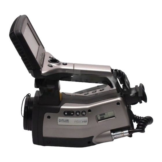
Page 75: Camera Overview
Camera overview Camera parts 10394103;a4 Figure 9.1 Camera parts, 1 Callout Description of part +/– buttons For more information about the functionality of this button, see section 9.2 – Keypad buttons & functions on page 75. F1 button For more information about the functionality of this button, see section 9.2 – Keypad buttons &... - Page 76 9 – Camera overview Callout Description of part F2 button For more information about the functionality of this button, see section 9.2 – Keypad buttons & functions on page 75. Camera status LCD For more information about the LCD, see section 9.5 – Camera status LCD on page 79.
- Page 77 9 – Camera overview 10568603;a1 Figure 9.2 Camera parts, 2 Callout Description of part C button For more information about the C button, see section 9.2 – Keypad buttons & functions on page 75. Lid of the battery compartment S button For more information about the S button, see section 9.2 –...
- Page 78 9 – Camera overview Callout Description of part Bluetooth® antenna For information about connecting a headset featuring Bluetooth® wireless tech- nology, see section 10.2.5.6 – Bluetooth® on page 120. ➲ Depending on your camera configuration, this feature may be an extra option. Lens Publ.
- Page 79 9 – Camera overview 10563403;a1 Figure 9.3 Video lamp, to be inserted in the RS-232/USB connector. The video lamp will automatically be switched on when the user switches to visual mode. Publ. No. 1558240 Rev. a156 – ENGLISH (EN) – March 1, 2006...
- Page 80 9 – Camera overview 10394403;a4 Figure 9.4 Camera parts, 3 Callout Description of part Cover for additional connectors Joystick For more information about the joystick, see section 9.2 – Keypad buttons & functions on page 75. ON/OFF button (green) For more information about the ON/OFF button, see section 9.2 – Keypad buttons &...
- Page 81 9 – Camera overview Callout Description of part IrDA infrared communication link (to communicate with the camera using a PDA, laptop computer etc.) For more information about using IrDA, see section 9.4 – IrDA infrared communi- cation link on page 78. Publ.
- Page 82 9 – Camera overview 10394603;a4 Figure 9.5 Camera parts, 4 Callout Description of part Spring-loaded locking latch for the remote control Publ. No. 1558240 Rev. a156 – ENGLISH (EN) – March 1, 2006...
- Page 83 9 – Camera overview Callout Description of part Laser LocatIR with lens cap ➲ Please note the following: A laser icon appears on the screen when the Laser LocatIR is switched on. ■ Since the distance between the laser beam and the image center will vary by ■...
- Page 84 9 – Camera overview 10395003;a3 Figure 9.6 Removable remote control Callout Description of part S button For more information about the S button, see section 9.2 – Keypad buttons & functions on page 75. C button For more information about the C button, see section 9.2 – Keypad buttons & functions on page 75.
-
Page 85: Keypad Buttons & Functions
9 – Camera overview Keypad buttons & functions Figure 9.7 Camera buttons – explanations Button Comments ON/OFF Press briefly to switch on the camera ■ Press and hold down for a few seconds to switch off the camera ■ Press briefly to autoadjust the camera ■... - Page 86 9 – Camera overview Button Comments Programmable functions: None ■ Adjust once ■ Auto focus ■ Reverse palette ■ Next palette ■ Visual/IR ■ Update ref temp ■ Button for Laser LocatIR Press to switch on Laser LocatIR Publ. No. 1558240 Rev. a156 – ENGLISH (EN) – March 1, 2006...
-
Page 87: Autofocus
9 – Camera overview Autofocus To focus the camera using the autofocus feature, press and hold down the A button for one second. ➲ Please note the following: The area that the camera uses when autofocusing is a 80 × 60 pixel box, centered ■... -
Page 88: Irda Infrared Communication Link
9 – Camera overview IrDA infrared communication link If you have access to a PDA or a laptop computer equipped with an IrDA infrared communication link, you can beam files to the internal flash memory in ThermaCAM™ P65 HS: If you beam a text comment file (*.tcf), it will be used as labels and values when ■... -
Page 89: Camera Status Lcd
9 – Camera overview Camera status LCD The camera status LCD on the left side of the camera displays information about battery status, communication status, memory status etc. 10346003;a3 Figure 9.8 Camera status LCD Figure 9.9 Camera status LCD – explanations Callout Comments Battery status bar. -
Page 90: Laser Locatir
9 – Camera overview Laser LocatIR The ThermaCAM™ P65 HS infrared camera features a laser pointer located at the front of the camera handle. To display the laser dot, press the Laser LocatIR button on left side of the handle. The laser dot will appear approx. 91 mm/3.6" above the target. -
Page 91: Visual Camera
9 – Camera overview Visual camera The ThermaCAM™ P65 HS infrared camera features a visual camera located at the front of the camera handle. The visual camera has no motorized focus and you will need to occasionally focus the camera by rotating the lens manually. Publ. - Page 92 9 – Camera overview INTENTIONALLY LEFT BLANK Publ. No. 1558240 Rev. a156 – ENGLISH (EN) – March 1, 2006...
-
Page 93: Camera Program
Camera program 10.1 Screen objects 10.1.1 Result table The results of measurement markers are displayed in a result table in the top right- hand corner of the screen. Figure 10.1 Explanation of measurement markers appearing in the result table Icon Explanation Spot Box 1, maximum temperature... -
Page 94: Status Bar
10 – Camera program 10.1.2 Status bar 10388403;a2 Figure 10.2 Status bar, showing atmospheric temperature, relative humidity, distance to target, zoom factor, date & time, temperature range, emissivity, and reflected ambient temperature. Information about an image and the current conditions appear on the first and second bottom lines of the screen. -
Page 95: Warning Messages
10 – Camera program Message Explanation Saving as Message is displayed while an image is being saved. 10.1.4.2 Warning messages Warning messages are displayed in the center of the screen. Here you will find impor- tant information about battery status, etc. Figure 10.5 Critical camera information –... -
Page 96: Menu System
10 – Camera program 10.2 Menu system 10.2.1 Navigating in the menu system Press the joystick to display the horizontal menu bar ■ Press the joystick to confirm selections in menus and dialog boxes ■ Press the C button to exit the menu system ■... -
Page 97: File Menu
10 – Camera program 10.2.2 File menu 10.2.2.1 Images 10565703;a2 Figure 10.6 Images folder Point to Images and press the joystick to display a thumbnail view of the files on the CompactFlash® card, or in the internal camera memory. The following files are dis- played: infrared images ■... -
Page 98: Save
10 – Camera program 10565803;a4 Figure 10.7 Images folder, showing the context menu In the Images folder you can do the following: Open an image by selecting the image using the joystick, then pressing the joystick. ■ For more information, see see section 8.2.2 – Opening an image on page 46. Create a new folder by selecting an image, then pressing and holding down the ■... -
Page 99: Copy To Card
10 – Camera program 10.2.2.3 Copy to card Point to Copy to card to copy the contents of the internal image folder to a automati- cally created folder on a CompactFlash® card 10.2.2.4 Periodic save 10389603;a3 Figure 10.8 Periodic save dialog box Point to Periodic save and press the joystick to display the Periodic save dialog box. - Page 100 10 – Camera program save specific frames as infrared images ■ play back the sequence backward and forward ■ set stop and start frames in a sequence to save a part of the sequence ■ choose between looped or linear recording mode ■...
-
Page 101: Voice Comment
10 – Camera program Callout Explanation As File type, select AVI (non-radiometric) or SEQ (radiometric). ■ As Record mode, select Circular or Linear. Circular means that the recording ■ will automatically start over when the internal RAM memory is full. This may be useful when it is extremely important that the beginning of an event is recorded, and it is difficult to start the recording at the exact time. -
Page 102: Text Comment
Point to Text comment and press the joystick to display the Text comment dialog box. Using the text comment feature, you can annotate images by using a file with predefined text strings. Such a file can be created and edited in FLIR Systems's PC software – for example, in ThermaCAM Reporter 7.0. - Page 103 Follow this procedure to beam a text comment file to the camera: Step Action ThermaCAM Reporter 7.0 – a reporting software from FLIR Systems – provides a user-friendly interface to create text comment files. For more information about using the text comment editor in ThermaCAM Reporter 7.0, consult any of the following manuals:...
- Page 104 10 – Camera program 10.2.2.7.2 Creating a text comment Figure 10.16 Creating a text comment Step Action Point to Text comment on the File menu and press the joystick. A dialog box with a number of tabs will appear on the screen. Move the joystick up/down to select a label on the first tab, and then press the joystick.
- Page 105 10 – Camera program 10.2.2.7.3 Creating a numerical value to be used in a text comment Follow this procedure to create a numerical value to be used in a text comment: Step Action Point to Text comment on the File menu and press the joystick. A dialog box with four tabs will appear on the screen.
- Page 106 10 – Camera program Step Action Move the joystick up/down and left/right to specify a numerical value. Spaces before and after the value will be deleted. 10566303;a3 To keep the text comment for future use, select Yes on the Settings tab. 10566403;a2 To include the numerical value in your text comment, go back to the first tab and select the value.
-
Page 107: Image Description
Using the image description feature, you can add a brief description to an image by using a Pocket PC and the IrDA infrared communication link on the camera. The image description can then be read out by other software – e.g. FLIR Systems ThermaCAM™ QuickView. -
Page 108: Analysis Menu
10 – Camera program 10.2.3 Analysis menu 10.2.3.1 Edit mode Point to Edit mode and press the joystick to enter the edit mode of the camera. When the camera is in edit mode you can select, move, and resize measurement markers as well as changing levels of isotherms etc. - Page 109 You can use this emissivity table to find emissivities for a number of different materials. An emissivity table can be created and edited in FLIR Systems’s PC software. ➲ The emissivity file can be stored at root level or at directory level.
-
Page 110: Add Box
10 – Camera program 10.2.3.3 Add box Point to Add box and press the joystick to add a box. A box will now appear on the screen. Press and hold down the joystick for one second when the box is selected to display a shortcut menu. - Page 111 You can use this emissivity table to find emissivities for a number of different materials. An emissivity table can be created and edited in FLIR Systems’s PC software. ➲ The emissivity file can be stored at root level or at directory level.
-
Page 112: Add Circle
10 – Camera program Label Value Comments Result To change how the measurement results will be ■ displayed, select Max, Min, or Avg. ■ ■ Show Max/Min To display two moving cursors inside the box, ■ continuously indicating the maximum and mini- ■... - Page 113 You can use this emissivity table to find emissivities for a number of different materials. An emissivity table can be created and edited in FLIR Systems’s PC software. ➲ The emissivity file can be stored at root level or at directory level.
-
Page 114: Add Line
10 – Camera program Label Value Comments Result To change how the circle displays the measure- ■ ment results, select Max, Min, or Avg. ■ ■ Show Max/Min To display two moving cursors inside the circle, ■ continuously indicating the maximum and mini- ■... - Page 115 10 – Camera program Command Explanation Point to Avg and press the joystick to display the average tempera- ture along the line. Settings See below. Point to Settings and press the joystick to display a Line settings dialog box where you can change the settings for the line.
- Page 116 You can use this emissivity table to find emissivities for a number of different materials. An emissivity table can be created and edited in FLIR Systems’s PC software. ➲ The emissivity file can be stored at root level or at directory level.
-
Page 117: Add Isotherm
10 – Camera program 10.2.3.6 Add isotherm The isotherm command colors all pixels with a temperature above, dual above, below, dual below or between one or more preset temperature levels. 10390903;a2 Figure 10.34 Temperature scale showing an isotherm set to above +62 °C Point to Add isotherm and press the joystick to add an isotherm. - Page 118 10 – Camera program Command Explanation Below All pixels with a temperature lower than a set temperature will be colored with the same preset isotherm color. Interval All pixels with a temperature within the set interval will be colored with the same preset isotherm color. Dual Above All pixels in two consecutive temperature ranges above a set temper- ature will be colored with two different preset isotherm colors.
-
Page 119: Add Diff
10 – Camera program Label Value Comments Attribute Transparent Selecting Transparent will add some transparency ■ to an isotherm color, making it easier for you to Solid ■ see objects through the color. To make the isotherm colors appear solid, select Solid. -
Page 120: Obj Par
Click Emissivity table to display an emissivity table on the screen. You can use this emissivity table to find emissivities for a number of different materials. An emissivity table can be created and edited in FLIR Systems’s PC software. ➲ Please note the following: The emissivity file can be stored at root level or at directory level. -
Page 121: Image Menu
10 – Camera program 10.2.4 Image menu 10.2.4.1 Visual/IR Point to Visual/IR and press the joystick to switch between visual mode and IR mode. 10.2.4.2 Freeze/Live Point to Freeze/Live and press the joystick to switch between freeze image mode and live image mode. It has the same effect as if you briefly press the S button. 10.2.4.3 Range 10391903;a6... -
Page 122: Manual Adjust / Continuous Adjust
■ Custom palettes (*.pal) can be used by the camera. For more information about how to create custom palettes, contact FLIR Systems. 10.2.4.7 Hide graphics Point to Hide graphics and press the joystick to hide all on-screen graphics (e.g. result table, status bar etc.). -
Page 123: Setup Menu
10 – Camera program 10.2.5 Setup menu ➲ Depending on camera configuration, some menu items on the Setup menu may be displayed in a different order, or on a submenu. 10.2.5.1 Image 10568403;a2 Figure 10.45 Image Setup dialog box Figure 10.46 Explanations of the Image Setup dialog box Label Value Comments... - Page 124 10 – Camera program Label Value Comments Lock scale Move the joystick left/right to lock the temperature ■ scale to maximum temperature, minimum temper- ■ atur or a certain temperature span. After having ■ set Lock scale to Max, Min or Span you will need Span ■...
- Page 125 ➲ Please note the following: Although the shutter period works independent- ■ ly of other functions described in this publica- tion, FLIR Systems recommends that Short is selected when using the camera for detection of face temperature. Selecting Normal will calibrate the camera at ■...
-
Page 126: Difference
10 – Camera program 10.2.5.2 Difference 10393203;a3 Figure 10.47 Difference settings dialog box Difference is a command that calculates the temperature difference between two measurement markers, or the reference temperature and a measurement marker. Figure 10.48 Explanations of the Difference settings dialog box Label Value Comments... -
Page 127: Save
10 – Camera program 10.2.5.3 Save 10568003;a2 Figure 10.49 Save Setup dialog box Figure 10.50 Explanations of the Save Setup dialog box Label Value Comments Prompt text comment If Yes is selected, the text comment dialog box will ■ appear when you save an image. This function ■... - Page 128 10 – Camera program Example IR_0003.jpg Comment The counter will be reset when exceeding 9999, or when you point to Factory default on the Setup menu and press the joystick. Figure 10.52 Naming based on current date – explanations Typical syntax: IR_YYMMDD_nnn.jpg IR or DC or SEQ or AVI IR = infrared image ■...
-
Page 129: Alarm
10 – Camera program 10.2.5.4 Alarm 10439703;a2 Figure 10.54 Alarm Setup dialog box Figure 10.55 Explanations of the Alarm setup dialog box Label Value Explanation Type Select Off to disable the alarm. ■ ■ Above Select Above to assign an alarm color to all ■... -
Page 130: Digital Video
10 – Camera program 10.2.5.5 Digital video ➲ Depending on your camera configuration, one of the digital video modes (DV or DCAM) may be an extra option. 10402903;a2 Figure 10.56 Digital video dialog box Figure 10.57 Explanations of the Digital video dialog box Label Value Comments... -
Page 131: Power
10 – Camera program Step Action Enter the pin code for the headset. You will find the pin code by consulting the documentation for the headset, but it is most likely 0000. After having entered the pin code, the dialog box will be closed. Now click Voice Comment on the File menu. -
Page 132: Status Bar
10 – Camera program 10.2.5.8 Status bar 10392803;a3 Figure 10.61 Status bar dialog box Figure 10.62 Explanations of the Status bar dialog box Label Value Comments Date/time Move the joystick left/right to enable/disable this ■ label on the status bar. ■... -
Page 133: Buttons
10 – Camera program 10.2.5.9 Buttons 10393103;a3 Figure 10.63 Buttons Settings dialog box Figure 10.64 Explanations of the Buttons Setting dialog box Label Value Comments None Move the joystick left/right to specify the function ■ of the F1 button on the left side of the camera. Adjust once ■... -
Page 134: Date/Time
10 – Camera program 10.2.5.10 Date/time 10393803;a3 Figure 10.65 Date/Time dialog box Figure 10.66 Explanations of the Date/Time dialog box Label Value Year 1970–2036 Month 1–12 1 –31 Hour 12 a.m.–12 p.m. ■ 1–24 ■ The format depends on the settings in the Local settings dialog box. Minute 00–59 Second... -
Page 135: Camera Info
10 – Camera program Label Value Video output NTSC ■ ■ Temp unit °C ■ °F ■ Distance unit Feet ■ Meters ■ Date format YYYY-MM-DD ■ YY-MM-DD ■ MM/DD/YY ■ DD/MM/YY ■ Time format 24 hour ■ AM/PM ■ 10.2.5.12 Camera info The Camera info dialog box shows information about memory usage, battery status,... - Page 136 10 – Camera program INTENTIONALLY LEFT BLANK Publ. No. 1558240 Rev. a156 – ENGLISH (EN) – March 1, 2006...
-
Page 137: Folder And File Structure
Folder and file structure The figure below shows the typical folder and file structure on a camera with an external CompactFlash™ card and internal camera memory, as it is appears using Windows® Explorer. The camera is the top node in the folder structure (Ircam01195) The external CompactFlash™... - Page 138 11 – Folder and file structure INTENTIONALLY LEFT BLANK Publ. No. 1558240 Rev. a156 – ENGLISH (EN) – March 1, 2006...
-
Page 139: Electrical Power System
Electrical power system The camera’s electrical power system consists of the following parts: a removable battery ■ a power supply ■ an internal battery charger ■ a stand-alone, external battery charger ■ The camera may powered either by using the battery, or by using the power supply. When using the power supply, the battery will –... -
Page 140: Internal Battery Charging
12 – Electrical power system 12.1 Internal battery charging To charge the battery internally, follow the instructions below. Step Action Make sure that the battery is correctly inserted into the camera. Connect the power supply cable to the camera. The message Charging battery will appear on the screen. While charging, the battery status symbol will pulse until the battery is fully charged. -
Page 141: External Battery Charging
12 – Electrical power system 12.2 External battery charging The battery status while charging is indicated by a number of LEDs. See the figure below. 10346203;a4 Figure 12.1 LED indicators on the stand-alone battery charger. Figure 12.2 LED indicators – explanations Situation Indicator # Color &... -
Page 142: Battery Safety Warnings
12 – Electrical power system 12.3 Battery safety warnings Do not place the battery in fire or heat the battery. ■ Do not install the battery backwards so that the polarity is reversed. ■ Do not connect the positive terminal and the negative terminal of the battery to ■... - Page 143 12 – Electrical power system The temperature range over which the battery can be discharged is -15–+45 °C ■ (+18.8–+113 °F). Use of the battery outside of this temperature range may damage the performance of the battery or may reduce its life expectancy. Publ.
- Page 144 12 – Electrical power system INTENTIONALLY LEFT BLANK Publ. No. 1558240 Rev. a156 – ENGLISH (EN) – March 1, 2006...
-
Page 145: Note On Lemo Connectors
A note on LEMO connectors 13.1 How to connect & disconnect LEMO connectors The male LEMO connectors used on the camera cables are designed to lock securely to the female connectors on the camera body. A connector consists of a fixed inner tube and a sliding outer tube. - Page 146 13 – A note on LEMO connectors 10403003;a1 Figure 13.2 Unlocking a LEMO connector Publ. No. 1558240 Rev. a156 – ENGLISH (EN) – March 1, 2006...
-
Page 147: Maintenance & Cleaning
Maintenance & cleaning 14.1 Camera body, cables & accessories The camera body, cables and accessories may be cleaned by wiping with a soft cloth. To remove stains, wipe with a soft cloth moistened with a mild detergent solution and wrung dry, then wipe with a dry soft cloth. ➲... - Page 148 14 – Maintenance & cleaning INTENTIONALLY LEFT BLANK Publ. No. 1558240 Rev. a156 – ENGLISH (EN) – March 1, 2006...
-
Page 149: Troubleshooting
Troubleshooting Problem Possible reason Solution The LCD on the remote The camera may have been switched off Press ON/OFF to switch on control, or the viewfinder, automatically due the settings in the Power the camera. displays no image at all. setup dialog box. - Page 150 15 – Troubleshooting Problem Possible reason Solution The LCD/viewfinder dis- The target may be out of focus. Focus the camera by plays an infrared image, but pressing and holding down it is blurry. the A button for a few sec- onds.
-
Page 151: Technical Specifications & Dimensional Drawings
Technical specifications & dimensional drawings ➲ FLIR Systems reserves the right to discontinue models, parts and accessories, and other items, or change specifications at any time without prior notice. 16.1 Imaging performance Spatial resolution 1.3 mrad Accuracy ± 2 °C/± 3.6 °F or ± 2 % of reading... -
Page 152: Correction Parameters
16 – Technical specifications & dimensional drawings 16.5 Correction parameters Emissivity correction Set by number, or by selection in predefined list Atmospheric transmission correction Automatic, based on input from distance, atmo- spheric temperature, and relative humidity. Optics transmission correction Automatic, based on signals from internal sensors Reflected ambient temperature correction External optics correction 16.6... -
Page 153: Physical Specifications
16 – Technical specifications & dimensional drawings 16.9 Physical specifications Total weight, including battery & remote control Camera type 218: 2.17 kg (4.78 lb) Camera type 234: 2.18 kg (4.80 lb) Camera type 253: 2.16 kg (4.76 lb) The three-digit camera type number is the three first digits in the camera S/N. -
Page 154: Pin Configurations
16 – Technical specifications & dimensional drawings 16.11 Pin configurations 16.11.1 RS-232/USB connector 10402703;a1 Figure 16.1 Pin configuration for RS-232/USB connector (on camera – operator’s side) Connector type: LEMO 1B, 6 pins Signal name Type Pin number USB_D+ USB_D- USB_POWER RS232_TX1 RS232_RX1 10563403;a1... -
Page 155: Remote Control Connector
16 – Technical specifications & dimensional drawings Luminous intensity: 35 000 mcd in the middle of the light beam; 20 000 mcd ■ measured at an angle of ±10° from the light beam, and 5 000 mcd measured at an angle of ±20° from the light beam. Connector type: LEMO 1B, 6 pins. -
Page 156: Power Connector
16 – Technical specifications & dimensional drawings 16.11.3 Power connector 10402503;a1 Figure 16.4 Pin configuration for power connector (on camera – operator’s side). A: Center pin; B: Chassis Connector type: 2.5 mm DC Signal name Type Pin number +12V POWER CENTER PIN POWER CHASSIS... - Page 157 16 – Technical specifications & dimensional drawings Connector type: FireWire, 4 pins Signal name Type Pin number TPB0- TPB0+ TPA0- TPA1+ Publ. No. 1558240 Rev. a156 – ENGLISH (EN) – March 1, 2006...
-
Page 158: Relationship Between Fields Of View And Distance
16 – Technical specifications & dimensional drawings 16.12 Relationship between fields of view and distance 10401803;a1 Figure 16.7 Relationship between fields of view and distance. 1: Distance to target; 2: VFOV = vertical field of view; 3: HFOV = horizontal field of view, 4: IFOV = instantaneous field of view (size of one detector element). - Page 159 16 – Technical specifications & dimensional drawings 10586503;a2 Figure 16.9 Horizontal, vertical and instantaneous fields of view for certain distances to targets. 124 mm lens / camera type 234. Publ. No. 1558240 Rev. a156 – ENGLISH (EN) – March 1, 2006...
- Page 160 16 – Technical specifications & dimensional drawings 10586603;a2 Figure 16.10 Horizontal, vertical and instantaneous fields of view for certain distances to targets. 124 mm lens / camera type 253. Publ. No. 1558240 Rev. a156 – ENGLISH (EN) – March 1, 2006...
- Page 161 16 – Technical specifications & dimensional drawings 10586703;a2 Figure 16.11 Horizontal, vertical and instantaneous fields of view for certain distances to targets. 72 mm lens / camera type 218. Publ. No. 1558240 Rev. a156 – ENGLISH (EN) – March 1, 2006...
- Page 162 16 – Technical specifications & dimensional drawings 10586803;a2 Figure 16.12 Horizontal, vertical and instantaneous fields of view for certain distances to targets. 72 mm lens / camera type 234. Publ. No. 1558240 Rev. a156 – ENGLISH (EN) – March 1, 2006...
- Page 163 16 – Technical specifications & dimensional drawings 10586903;a2 Figure 16.13 Horizontal, vertical and instantaneous fields of view for certain distances to targets. 72 mm lens / camera type 253. Publ. No. 1558240 Rev. a156 – ENGLISH (EN) – March 1, 2006...
- Page 164 16 – Technical specifications & dimensional drawings 10587003;a2 Figure 16.14 Horizontal, vertical and instantaneous fields of view for certain distances to targets. 36 mm lens / camera type 218. Publ. No. 1558240 Rev. a156 – ENGLISH (EN) – March 1, 2006...
- Page 165 16 – Technical specifications & dimensional drawings 10587103;a3 Figure 16.15 Horizontal, vertical and instantaneous fields of view for certain distances to targets. 36 mm lens / camera type 234 & 281. Publ. No. 1558240 Rev. a156 – ENGLISH (EN) – March 1, 2006...
- Page 166 16 – Technical specifications & dimensional drawings 10587203;a2 Figure 16.16 Horizontal, vertical and instantaneous fields of view for certain distances to targets. 36 mm lens / camera type 253. Publ. No. 1558240 Rev. a156 – ENGLISH (EN) – March 1, 2006...
- Page 167 16 – Technical specifications & dimensional drawings 10587303;a2 Figure 16.17 Horizontal, vertical and instantaneous fields of view for certain distances to targets. 18 mm lens / camera type 218. Publ. No. 1558240 Rev. a156 – ENGLISH (EN) – March 1, 2006...
- Page 168 16 – Technical specifications & dimensional drawings 10587403;a2 Figure 16.18 Horizontal, vertical and instantaneous fields of view for certain distances to targets. 18 mm lens / camera type 234. Publ. No. 1558240 Rev. a156 – ENGLISH (EN) – March 1, 2006...
- Page 169 16 – Technical specifications & dimensional drawings 10587503;a2 Figure 16.19 Horizontal, vertical and instantaneous fields of view for certain distances to targets. 18 mm lens / camera type 253. Publ. No. 1558240 Rev. a156 – ENGLISH (EN) – March 1, 2006...
- Page 170 16 – Technical specifications & dimensional drawings 10587603;a2 Figure 16.20 Horizontal, vertical and instantaneous fields of view for certain distances to targets. 9 mm lens / camera type 218. Publ. No. 1558240 Rev. a156 – ENGLISH (EN) – March 1, 2006 Test Equipment Depot - 800.517.8431 - 99 Washington Street Melrose, MA 02176 FAX 781.665.0780 - TestEquipmentDepot.com...
- Page 171 16 – Technical specifications & dimensional drawings 10587703;a2 Figure 16.21 Horizontal, vertical and instantaneous fields of view for certain distances to targets. 9 mm lens / camera type 234. Publ. No. 1558240 Rev. a156 – ENGLISH (EN) – March 1, 2006...
- Page 172 16 – Technical specifications & dimensional drawings 10587803;a2 Figure 16.22 Horizontal, vertical and instantaneous fields of view for certain distances to targets. 9 mm lens / camera type 253. Figure 16.23 F-number and close focus limits for various lenses Lens → 124 mm 72 mm 36 mm...
-
Page 173: Basic Dimensions - Battery Charger
16 – Technical specifications & dimensional drawings 16.13 Basic dimensions – battery charger 10388003;a4 Figure 16.24 Overall dimensions of the battery charger Publ. No. 1558240 Rev. a156 – ENGLISH (EN) – March 1, 2006... -
Page 174: Basic Dimensions - Battery
16 – Technical specifications & dimensional drawings 16.14 Basic dimensions – battery 10388103;a4 Figure 16.25 Overall dimensions of the battery Publ. No. 1558240 Rev. a156 – ENGLISH (EN) – March 1, 2006... -
Page 175: Basic Dimensions - Remote Control
16 – Technical specifications & dimensional drawings 16.15 Basic dimensions – remote control 10394003;a4 Figure 16.26 Overall dimensions of the remote control Publ. No. 1558240 Rev. a156 – ENGLISH (EN) – March 1, 2006... -
Page 176: Basic Dimensions - Camera
16 – Technical specifications & dimensional drawings 16.16 Basic dimensions – camera 10346503;a4 Figure 16.27 Overall dimensions of the camera. For camera type 253, replace 234 mm / 9.21" with 241 mm / 9.49". Three-digit camera type number is stated on configuration label. Publ. -
Page 177: Basic Dimensions - Camera
16 – Technical specifications & dimensional drawings 16.17 Basic dimensions – camera 10563203;a2 Figure 16.28 Overall dimensions of the camera, when the video lamp is mounted Publ. No. 1558240 Rev. a156 – ENGLISH (EN) – March 1, 2006... -
Page 178: Basic Dimensions - Camera
16 – Technical specifications & dimensional drawings 16.18 Basic dimensions – camera 10352203;a4 Figure 16.29 Location of the standard tripod mount (1/4"-20). For camera type 253, replace 100 mm / 3.94" with 107 mm / 4.21". Three-digit camera type number is stated on configuration label. Publ. -
Page 179: Basic Dimensions - Video Lamp
16 – Technical specifications & dimensional drawings 16.19 Basic dimensions – video lamp 10563303;a2 Figure 16.30 Overall dimensions of the video lamp Publ. No. 1558240 Rev. a156 – ENGLISH (EN) – March 1, 2006... - Page 180 16 – Technical specifications & dimensional drawings INTENTIONALLY LEFT BLANK Publ. No. 1558240 Rev. a156 – ENGLISH (EN) – March 1, 2006...
-
Page 181: Glossary
Glossary Term or expression Explanation absorption (absorption factor) The amount of radiation absorbed by an object relative to the received radiation. A number between 0 and 1. ambient Objects and gases that emit radiation towards the object being measured. atmosphere The gases between the object being measured and the camera, normally air. - Page 182 17 – Glossary Term or expression Explanation estimated atmospheric transmission A transmission value, supplied by a user, replacing a calculated external optics Extra lenses, filters, heat shields etc. that can be put between the camera and the object being measured. filter A material transparent only to some of the infrared wavelengths.
- Page 183 17 – Glossary Term or expression Explanation object signal A non-calibrated value related to the amount of radiation re- ceived by the camera from the object. palette The set of colors used to display an IR image. pixel Stands for picture element. One single spot in an image. radiance Amount of energy emitted from an object per unit of time, area and angle (W/m...
- Page 184 17 – Glossary Term or expression Explanation transmission (or transmittance) factor Gases and materials can be more or less transparent. Transmis- sion is the amount of IR radiation passing through them. A number between 0 and 1. transparent isotherm An isotherm showing a linear spread of colors, instead of cover- ing the highlighted parts of the image.
-
Page 185: Thermographic Measurement Techniques
Thermographic measurement techniques 18.1 Introduction An infrared camera measures and images the emitted infrared radiation from an object. The fact that radiation is a function of object surface temperature makes it possible for the camera to calculate and display this temperature. However, the radiation measured by the camera does not only depend on the tem- perature of the object but is also a function of the emissivity. -
Page 186: Finding The Emissivity Of A Sample
18 – Thermographic measurement techniques 18.2.1 Finding the emissivity of a sample 18.2.1.1 Step 1: Determining reflected apparent temperature Use one of the following two methods to determine reflected apparent temperature: 18.2.1.1.1 Method 1: Direct method Step Action Look for possible reflection sources, considering that the incident angle = reflection angle (a = b). - Page 187 18 – Thermographic measurement techniques Step Action Measure the radiation intensity (= apparent temperature) from the reflecting source using the following settings: Emissivity: 1.0 ■ ■ You can measure the radiation intensity using one of the following two methods: 10589003;a2 Figure 18.3 1 = Reflection source ➲...
-
Page 188: Step 2: Determining The Emissivity
18 – Thermographic measurement techniques Step Action Measure the apparent temperature of the aluminum foil and write it down. 10727003;a2 Figure 18.4 Measuring the apparent temperature of the aluminum foil 18.2.1.2 Step 2: Determining the emissivity Step Action Select a place to put the sample. Determine and set reflected apparent temperature according to the previous pro- cedure. -
Page 189: Reflected Apparent Temperature
50 %. 18.6 Other parameters In addition, some cameras and analysis programs from FLIR Systems allow you to compensate for the following parameters: Atmospheric temperature – i.e. the temperature of the atmosphere between the ■...
Need help?
Do you have a question about the ThermaCAM P65 HS and is the answer not in the manual?
Questions and answers