Table of Contents
Advertisement
Quick Links
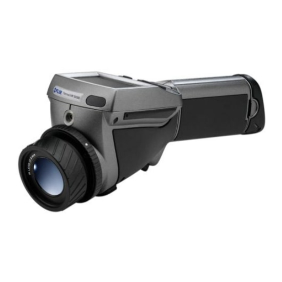
ThermaCAM™ EX300
Benutzerhandbuch
User's manual –
Benutzerhandbuch
nual –
–
ználói kézikönyv – Käyttäjän opas –
dning
– Brukerveiledning – Instrukcja obsługi –
Kılavuzu – Uživatelská příručka –
Publ. No.
Revision
Language
Issue date
–
Manual del usuario
Manuel de l'utilisateur
–
Manual del usuario
Betjeningsvejledning
Bruksanvisning
Gebruikershandleiding
1558439
a156
English (EN)
February 28, 2006
Manuel de l'utilisateur
–
Manual do utilizador
– Manuale dell'utente –
– Brukerveiledning – Instrukcja obsługi –
– Kullanım Kılavuzu – Uživatelská příručka –
User's manual
Manual do utilizador
– Manuale dell'utente –
– Felhasználói kézikönyv – Käyttäjän opas –
Bruksanvisning
Gebruikershandleiding
– Felhas-
Betjenings-
– Kullanım
Advertisement
Table of Contents

Related Manuals for FLIR ThermaCAM EX300


Summary of Contents for FLIR ThermaCAM EX300
- Page 1 ThermaCAM™ EX300 Benutzerhandbuch Manuel de l’utilisateur Manual do utilizador User’s manual – – – – Manuale dell’utente – – Felhas- Manual del usuario Betjenings- Benutzerhandbuch Manuel de l’utilisateur Manual do utilizador nual – – – – Manuale dell’utente – – Felhasználói kézikönyv – Käyttäjän opas – Manual del usuario Bruksanvisning Betjeningsvejledning...
- Page 3 Warnings & cautions Important note about this manual Welcome! Packing list System overview Connecting system components Introduction to thermographic inspections of electrical installations Tutorials Camera overview Camera program Electrical power system Maintenance & cleaning Troubleshooting Technical specifications & dimensional drawings Glossary...
- Page 5 Thermographic measurement techniques History of infrared technology Theory of thermography Emissivity tables...
- Page 7 ThermaCAM™ EX300 User’s manual Publ. No. 1558439 Rev. a156 – ENGLISH (EN) – February 28, 2006...
- Page 8 FLIR Systems or this warranty will not apply. FLIR Systems will, at its option, repair or replace any such defective product free of charge if, upon inspection, it proves to be defective in material or workmanship and provided that it is returned to FLIR Systems within the said one-year period.
- Page 9 Designation Status Reg. No. Germany Patent 60004227.8 Great Britain Design Patent 106017 Great Britain Design Patent 3006596 Great Britain Design Patent 3006597 Great Britain Patent 1188086 International Design Patent DM/057692 International Design Patent DM/061609 Japan Application 2000-620406 Japan Application 2002-588123 Japan Application 2002-588070...
- Page 10 Designation Status Reg. No. U.S. Pending 29/233,400 Publ. No. 1558439 Rev. a156 – ENGLISH (EN) – February 28, 2006...
-
Page 11: Table Of Contents
Table of contents Warnings & cautions ........................Important note about this manual ....................Welcome! ............................About FLIR Systems ......................3.1.1 A few images from our facilities ................Comments & questions ......................Packing list ............................System overview ..........................Connecting system components .................... - Page 12 Tutorials ............................Switching on & switching off the camera ................8.1.1 Switching on the camera ..................8.1.2 Switching off the camera ..................Working with images ......................8.2.1 Acquiring an image ....................8.2.2 Freezing an image ....................8.2.3 Saving an image ....................8.2.4 Deleting one or several images ................
- Page 13 10.4.6 Range (extra option) ..................... 10.4.7 Hide graphics / Show graphics ................10.4.8 File ......................... 10.4.9 Setup ........................10.4.9.1 Settings ..................... 10.4.9.2 Date/time ................... 10.4.9.3 Local settings ..................10.4.9.4 Camera info ..................10.4.9.5 Factory default ................... 11 Electrical power system ......................... 11.1 Internal battery charging ......................
- Page 14 18.3.1 Planck’s law ......................18.3.2 Wien’s displacement law ..................18.3.3 Stefan-Boltzmann's law ..................18.3.4 Non-blackbody emitters ..................18.4 Infrared semi-transparent materials ..................19 Emissivity tables ..........................19.1 References ..........................19.2 Important note about the emissivity tables ................19.3 Tables ............................ Index ..............................
-
Page 15: Warnings & Cautions
Each camera from FLIR Systems is calibrated prior to shipping. It is advisable that ■ the camera is sent in for calibration once a year. - Page 16 1 – Warnings & cautions INTENTIONALLY LEFT BLANK Publ. No. 1558439 Rev. a156 – ENGLISH (EN) – February 28, 2006...
-
Page 17: Important Note About This Manual
Important note about this manual As far as it is practically possible, FLIR Systems configures each manual to reflect each customer’s particular camera configuration. However, please note the following exceptions: The packing list is subject to specific customer configuration and may contain more ■... - Page 18 2 – Important note about this manual INTENTIONALLY LEFT BLANK Publ. No. 1558439 Rev. a156 – ENGLISH (EN) – February 28, 2006...
-
Page 19: Welcome
The images can be analyzed either in the field by using the real-time measurement functions built into the camera, or in a PC using FLIR Systems ThermaCAM Reporter software by downloading the images from the camera using ThermaCAM™ QuickView. -
Page 20: About Flir Systems
Figure 3.2 Indigo Operations, Niceville, USA, and Indigo Operations, Santa Barbara, USA. Indigo Operations is a division of FLIR Systems. As pioneers in the IR industry, FLIR Systems has a long list of ‘firsts’ the world of in- frared thermography: 1965: 1st thermal imaging system for predictive maintenance (Model 650). - Page 21 10 L (2.6 US gallon) jar with liquid nitrogen. To the left of the oscilloscope the Polaroid attachment (6 kg/13 lb) can be seen. RIGHT: FLIR Systems ThermaCAM Model E2 from 2002 – weight: 0.7 kg (1.54 lb), including battery.
-
Page 22: A Few Images From Our Facilities
3 – Welcome! 3.1.1 A few images from our facilities 10401303;a1 Figure 3.4 LEFT: Development of system electronics; RIGHT: Testing of an FPA detector 10401403;a1 Figure 3.5 LEFT: Diamond turning machine; RIGHT: Lens polishing Publ. No. 1558439 Rev. a156 – ENGLISH (EN) – February 28, 2006... - Page 23 3 – Welcome! 10401503;a1 Figure 3.6 LEFT: Testing of IR cameras in the climatic chamber; RIGHT: Robot for camera testing and calibration Publ. No. 1558439 Rev. a156 – ENGLISH (EN) – February 28, 2006...
-
Page 24: Comments & Questions
3 – Welcome! Comments & questions FLIR Systems is committed to a policy of continuous development, and although we have tested and verified the information in this manual to the best of our ability, you may find that features and specifications have changed since the time of printing. -
Page 25: Packing List
The ThermaCAM™ EX300 and its accessories are delivered in a hard transport case which typically contains the items below. On receipt of the transport case, inspect all items and check them against the delivery note. Any damaged items must be reported to the local FLIR Systems representative immediately. Description Part Number Qty. - Page 26 4 – Packing list INTENTIONALLY LEFT BLANK Publ. No. 1558439 Rev. a156 – ENGLISH (EN) – February 28, 2006...
-
Page 27: System Overview
System overview This system overview shows all accessories that are possible to order for a Therma- CAM™ EX300. 10582303;a2 Figure 5.1 System overview Publ. No. 1558439 Rev. a156 – ENGLISH (EN) – February 28, 2006... - Page 28 5 – System overview INTENTIONALLY LEFT BLANK Publ. No. 1558439 Rev. a156 – ENGLISH (EN) – February 28, 2006...
-
Page 29: Connecting System Components
Connecting system components 10438203;a2 Figure 6.1 How to connect system components Figure 6.2 Explanations of callouts Callout Explanation Power supply cable (11–16 VDC) USB / RS-232 cable Video cable (CVBS, i.e. composite video) Publ. No. 1558439 Rev. a156 – ENGLISH (EN) – February 28, 2006... - Page 30 6 – Connecting system components INTENTIONALLY LEFT BLANK Publ. No. 1558439 Rev. a156 – ENGLISH (EN) – February 28, 2006...
-
Page 31: Introduction To Thermographic Inspections Of Electrical Installations
Introduction to thermographic inspections of electrical installations Important note All camera functions and features that are described in this section may not be sup- ported by your particular camera configuration. Electrical regulations differ from country to country. For that reason, the electrical procedures described in this section may not be the standard of procedure in your particular country. -
Page 32: General Equipment Data
7 – Introduction to thermographic inspections of electrical installations and for the climatic zones. The measurement periods may also differ depending on the type of plant to be inspected, whether they are hydroelectric, nuclear, coal-based or oil-based plants. In the industry the inspections are—at least in Nordic countries with clear seasonal differences—carried out during spring or autumn or before longer stops in the oper- ation. -
Page 33: Inspection
7 – Introduction to thermographic inspections of electrical installations The more the IR camera operator knows about the equipment that he or she is about to inspect, the higher the quality of the inspection. But it is virtually impossible for an IR thermographer to have detailed knowledge about all the different types of equipment that can be controlled. -
Page 34: Priority
7 – Introduction to thermographic inspections of electrical installations The classification of the defects gives a more detailed meaning that not only takes into account the situation at the time of inspection (which is certainly of great impor- tance), but also the possibility to normalize the over-temperature to standard load and ambient temperature conditions. -
Page 35: Control
7 – Introduction to thermographic inspections of electrical installations However, the most common result of the identification and classification of the detected faults is a recommendation to repair immediately or as soon as it is practically possible. It is important that the repair crew is aware of the physical principles for the identifica- tion of defects. -
Page 36: Measurement Technique For Thermographic Inspection Of Electrical Installations
7 – Introduction to thermographic inspections of electrical installations Measurement technique for thermographic inspection of electrical installations 7.3.1 How to correctly set the equipment A thermal image may show high temperature variations: 10712803;a4 Figure 7.2 Temperature variations in a fusebox In the images above, the fuse to the right has a maximum temperature of +61°C (+142°F), whereas the one to the left is maximum +32°C (+90°F) and the one in the middle somewhere in between. - Page 37 7 – Introduction to thermographic inspections of electrical installations to be in for the moment. It might be so that you measure heat, which has been con- ducted over some distance, whereas the ‘real’ hot spot is hidden from you. An example is shown in the image below.
-
Page 38: Comparative Measurement
7 – Introduction to thermographic inspections of electrical installations 7.3.3 Comparative measurement For thermographic inspections of electrical installations a special method is used, which is based on comparison of different objects, so-called measurement with a reference. This simply means that you compare the three phases with each other. This method needs systematic scanning of the three phases in parallel in order to assess whether a point differs from the normal temperature pattern. -
Page 39: Normal Operating Temperature
7 – Introduction to thermographic inspections of electrical installations 10713303;a4 Figure 7.7 A profile (line) in an infrared image and a graph displaying the increasing temperature 7.3.4 Normal operating temperature Temperature measurement with thermography usually gives the absolute temperature of the object. In order to correctly assess whether the component is too hot, it is necessary to know its operating temperature, that is, its normal temperature if we consider the load and the temperature of its environment. -
Page 40: Classification Of Faults
7 – Introduction to thermographic inspections of electrical installations 10713503;a4 Figure 7.9 An infrared image of indoor electrical equipment (2) The two left phases are considered as normal, whereas the right phase shows a very clear excess temperature. Actually, the operating temperature of the left phase is +68°C (+154°F), that is, quite a substantial temperature, whereas the faulty phase to the right shows a temperature of +86°C (+187°F). - Page 41 7 – Introduction to thermographic inspections of electrical installations < 5°C (9°F) The start of the overheat condi- tion. This must be carefully monitored. 5–30°C (9–54°F) Developed overheating. It must be repaired as soon as possible (but think about the load situa- tion before a decision is made).
-
Page 42: Reporting
The program, which has been used for creating the report page shown below, is called ThermaCAM™ Reporter. It is adapted to several types of infrared cameras from FLIR Systems. A professional report is often divided into two sections: Front pages, with facts about the inspection, such as: ■... - Page 43 7 – Introduction to thermographic inspections of electrical installations 10713603;a3 Figure 7.10 A report example Publ. No. 1558439 Rev. a156 – ENGLISH (EN) – February 28, 2006...
-
Page 44: Different Types Of Hot Spots In Electrical Installations
7 – Introduction to thermographic inspections of electrical installations Different types of hot spots in electrical installations 7.5.1 Reflections The thermographic camera sees any radiation that enters the lens, not only originating from the object that you are looking at, but also radiation that comes from other sources and has been reflected by the target. -
Page 45: Inductive Heating
7 – Introduction to thermographic inspections of electrical installations 10713803;a3 Figure 7.12 An infrared image of a circuit breaker 7.5.3 Inductive heating 10713903;a3 Figure 7.13 An infrared image of hot stabilizing weights Eddy currents can cause a hot spot in the current path. In cases of very high currents and close proximity of other metals, this has in some cases caused serious fires. -
Page 46: Varying Cooling Conditions
7 – Introduction to thermographic inspections of electrical installations 10714003;a3 Figure 7.14 Examples of infrared images of load variations The image to the left shows three cables next to each other. They are so far apart that they can be regarded as thermally insulated from each other. The one in the middle is colder than the others. -
Page 47: Resistance Variations
7 – Introduction to thermographic inspections of electrical installations 7.5.6 Resistance variations Overheating can have many origins. Some common reasons are described below. Low contact pressure can occur when mounting a joint, or through wear of the mate- rial, for example, decreasing spring tension, worn threads in nuts and bolts, even too much force applied at mounting. - Page 48 7 – Introduction to thermographic inspections of electrical installations 10714303;a3 Figure 7.17 Overheating in a circuit breaker The overheating of this circuit breaker is most probably caused by bad contact in the near finger of the contactor. Thus, the far finger carries more current and gets hotter. The component in the infrared image and in the photo is not the same, however, it is similar).
-
Page 49: Disturbance Factors At Thermographic Inspection Of Electrical Installations
7 – Introduction to thermographic inspections of electrical installations Disturbance factors at thermographic inspection of electrical installations During thermographic inspections of different types of electrical installations, distur- bance factors such as wind, distance to object, rain or snow often influence the measurement result. -
Page 50: Distance To Object
7 – Introduction to thermographic inspections of electrical installations snow or rain and reliable measurement is no longer possible. This is mainly because a heavy snowfall as well as heavy rain is impenetrable to infrared radiation and it is rather the temperature of the snowflakes or raindrops that will be measured. 7.6.3 Distance to object This image is taken from a helicopter 20 meters (66 ft.) away from this faulty connec-... -
Page 51: Object Size
The reason for this effect is that there is a smallest object size, which gives correct temperature measurement. This smallest size is indicated to the user in all FLIR Sys- tems cameras. The image below shows what you see in the viewfinder of camera model 695. - Page 52 7 – Introduction to thermographic inspections of electrical installations 10714703;a3 Figure 7.21 Image from the viewfinder of a ThermaCAM 695 This effect is due to imperfections in the optics and to the size of the detector elements. It is typical for all infrared cameras and can not be avoided. Publ.
-
Page 53: Practical Advice For The Thermographer
7 – Introduction to thermographic inspections of electrical installations Practical advice for the thermographer Working in a practical way with a camera, you will discover small things that make your job easier. Here are ten of them to start with. 7.7.1 From cold to hot You have been out with the camera at +5°C (+41°F). -
Page 54: Reflected Apparent Temperature
7 – Introduction to thermographic inspections of electrical installations 7.7.4 Reflected apparent temperature You are in a measurement situation where there are several hot sources that influence your measurement. You need to have the right value for the reflected apparent tem- perature to input into the camera and thus get the best possible correction. -
Page 55: Tutorials
Tutorials Switching on & switching off the camera 8.1.1 Switching on the camera Step Action Insert the battery into the battery compartment. Press PWR/NO to switch on the camera. 8.1.2 Switching off the camera Step Action To switch off the camera, press and hold down PWR/NO until the message Shutting down... -
Page 56: Working With Images
8 – Tutorials Working with images 8.2.1 Acquiring an image Step Action Point the camera at a warm object, like a face or a hand. Adjust the focus by turning the focus ring at the front of the lens. ➲ Please note what is the locking ring and what is the focus ring in the figure on page 49. -
Page 57: Deleting One Or Several Images
8 – Tutorials 8.2.4 Deleting one or several images Step Action Press MENU/YES to display the vertical menu bar. Point to File on the vertical menu bar and press the MENU/YES. Point to Delete image or Delete all images and press MENU/YES to delete one or several images. -
Page 58: Working With Measurements
8 – Tutorials Working with measurements 8.3.1 Laying out a spot ➲ The camera requires a warm-up time of 5 minutes before accurate measurements can be expected. Step Action Press MENU/YES to display the vertical menu bar. Point to Meas. mode on the vertical menu bar and press MENU/YES. Select Spot in the Meas. -
Page 59: Working With Alarms
8 – Tutorials Working with alarms 8.4.1 Setting up a color alarm 8.4.1.1 Setting a color alarm using the menu system Step Action Press MENU/YES to display the vertical menu bar. Point to Meas. mode on the vertical menu bar and press MENU/YES. Enable the color alarm and select its mode –... -
Page 60: Changing Level & Span
8 – Tutorials Changing level & span 8.5.1 Changing level Step Action Press MENU/YES to display the vertical menu bar. Point to Manual adjust on the vertical menu bar and press MENU/YES. Press the navigation pad up/down to change the level. An arrow pointing upwards or downwards will be displayed. -
Page 61: Changing System Settings
8 – Tutorials Changing system settings 8.6.1 Changing language Step Action Press MENU/YES to display the vertical menu bar. Point to Local Settings on the Setup menu and press MENU/YES. Press the navigation pad up/down to select Language. Press the navigation pad left/right to change the language. Press MENU/YES to confirm your changes and leave the dialog box. -
Page 62: Changing Date & Time
8 – Tutorials Step Action Press MENU/YES to confirm your changes and leave the dialog box. 8.6.5 Changing date & time Step Action Press MENU/YES to display the vertical menu bar. Point to Date/time on the Setup menu and press MENU/YES. Press the navigation pad up/down to select year, month, day, hour, minute and second. -
Page 63: Working With The Camera
8 – Tutorials Working with the camera 8.7.1 Removing the lens ➲ Please note the following: Before trying to remove fingerprints or other marks on the lens elements, see section ■ 12.2 – Lenses on page 79. Removing an IR lens will expose very sensitive camera parts. Do not touch any ■... -
Page 64: Adjusting The Focus
8 – Tutorials 10396303;a3 Figure 8.2 Removing a lens Step Action Rotate the locking ring on the camera 30° counter-clock-wise until the index mark is lined up with the laser window. Carefully pull out the lens. Do not use excessive force. 8.7.2 Adjusting the focus ➲... -
Page 65: Inserting The Battery
8 – Tutorials 8.7.3.1 Inserting the battery 10396403;a2 Figure 8.3 Inserting the battery Step Action Remove lid of the battery compartment by pressing the locking mechanism. Insert the battery with the connectors facing the rear end of the camera and the arrow symbol facing the front end of the camera. -
Page 66: Electrical Power System
8 – Tutorials For more information about the battery system, see section 11 – Electrical power system on page 73. Publ. No. 1558439 Rev. a156 – ENGLISH (EN) – February 28, 2006... -
Page 67: Camera Overview
Camera overview Camera parts 10581503;a1 Figure 9.1 Camera parts – front view Callout Description of part – Lid of the battery compartment Ring for hand strap Publ. No. 1558439 Rev. a156 – ENGLISH (EN) – February 28, 2006... - Page 68 9 – Camera overview Callout Description of part Laser LocatIR with lens cap ➲ Please note the following: A laser icon appears on the screen when the Laser LocatIR is switched on. ■ Since the distance between the laser beam and the image center will vary by ■...
- Page 69 9 – Camera overview 10581903;a1 Figure 9.2 Camera parts – view from below Callout Description of part Tripod mount Trigger Lid of the battery compartment Publ. No. 1558439 Rev. a156 – ENGLISH (EN) – February 28, 2006...
- Page 70 9 – Camera overview 10310603;a5 Figure 9.3 Camera parts – view from above Callout Description of part SEL button For more information about the functionality of this button, see section 9.2 – Keypad buttons & functions on page 57 SAVE/FRZ button For more information about the functionality of this button, see section 9.2 –...
-
Page 71: Keypad Buttons & Functions
9 – Camera overview Keypad buttons & functions Button Comments SAVE/FRZ button Briefly press SAVE/FRZ to freeze the current image and display ■ a dialog box where you can choose to save or cancel the image Press and hold down SAVE/FRZ for more than one second to ■... - Page 72 9 – Camera overview Button Comments Trigger Pull the trigger to do one of the following: Save the image ■ Switch on or switch off the Laser LocatIR ■ Autoadjust the camera ■ The function of the trigger depends on the trigger settings in the Settings dialog box.
-
Page 73: Laser Locatir
9 – Camera overview Laser LocatIR By pulling the trigger on the bottom side of the camera body, a laser dot appears approx. 40 mm/1.57" above the target. ➲ Please note the following: A laser icon appears on the screen when the Laser LocatIR is switched on. ■... -
Page 74: Led Indicator On Keypad
9 – Camera overview LED indicator on keypad Figure 9.6 Explanations of the LED indicator on the keypad Indicator mode Explanation Continuous green light Powering up or operating. Flashing green light Battery charging in standby mode. (0.25 sec. switched on + 0.25 sec. switched off) Flashing green light Battery charging in power-on mode. -
Page 75: Camera Program
Camera program 10.1 Result table The results of measurement markers are displayed in a result table in the top right- hand corner of the screen. Figure 10.1 Explanation of measurement markers appearing in the result table Icon Explanation Spot Area, maximum temperature Area, minimum temperature Area, average temperature Color alarm above... -
Page 76: System Messages
10 – Camera program 10.2 System messages 10.2.1 Status messages Status messages are displayed at the bottom of the screen, or in the top left part of the screen. Here you will find information about the current status of the camera. Figure 10.2 Status messages –... -
Page 77: Selecting Screen Objects
10 – Camera program 10.3 Selecting screen objects 10.3.1 Selecting screen objects Some screen objects – e.g. the scale, the information field, a spot etc. – can be se- lected by pressing SEL repeatedly until the object is either highlighted or surrounded by small brackets. - Page 78 10 – Camera program 10383403;a3 Figure 10.6 A selected color alarm. Press the navigation pad up/down at this stage to increase/decrease the color alarm temperature. 10383803;a3 Figure 10.7 A selected emissivity field. Press the navigation pad up/down at this stage to increase/decrease the emissivity.
-
Page 79: Menu System
10 – Camera program 10.4 Menu system 10.4.1 Navigating the menu system Press MENU/YES to display the vertical menu bar ■ Press MENU/YES to confirm selections in menus and dialog boxes ■ Press PWR/NO to exit the menu system ■ Press PWR/NO to cancel selections in menus and dialog boxes ■... -
Page 80: Emissivity
10 – Camera program Press the navigation pad left/right to change the span (indicated by two arrows ■ pointing away from each other or towards each other) 10392103;a3 Figure 10.9 Symbols in the temperature scale, indicating (1) increasing span; (2) decreasing span; (3) increasing level, and (4) decreasing level Point to Automatic adjust and press MENU/YES to put the camera in automatic mode, continuously optimizing the image for best level and span. -
Page 81: Palette
10 – Camera program 10.4.5 Palette 10382603;a4 Figure 10.11 Palette dialog box Point to Palette on the vertical menu bar and press MENU/YES to display the Palette dialog box. To select another palette, press the navigation pad left/right ■ To confirm the choice, press MENU/YES ■... -
Page 82: File
10 – Camera program 10.4.8 File 10568803;a2 Figure 10.12 File menu Figure 10.13 Explanations of the File menu Command Explanation Images Point to Images and press the joystick to display a thumbnail view of the images in the internal camera memory. Open an image by selecting the image using the joystick, then pressing MENU/YES. -
Page 83: Setup
10 – Camera program 10.4.9 Setup 10383003;a4 Figure 10.14 Setup menu 10.4.9.1 Settings 10382003;a4 Figure 10.15 Settings dialog box Figure 10.16 Explanations of the Settings dialog box Label Value Explanation Scale Select On to display the scale on the screen ■... -
Page 84: Date/Time
10 – Camera program Label Value Explanation Auto power off None If the camera is switched on but currently not used, ■ it will automatically be switched off after a specified 2 min ■ time. 5 min ■ 10 min ■... -
Page 85: Local Settings
10 – Camera program 10.4.9.3 Local settings 10567103;a2 Figure 10.19 Local settings dialog box Figure 10.20 Explanations of the Local settings dialog box Label Explanation Language Configuration-dependent Video output NTSC ■ ■ Temp unit °C – degrees Celsius or ■ °F –... - Page 86 10 – Camera program INTENTIONALLY LEFT BLANK Publ. No. 1558439 Rev. a156 – ENGLISH (EN) – February 28, 2006...
-
Page 87: Electrical Power System
Electrical power system The camera’s electrical power system consists of the following parts: a removable battery ■ a power supply ■ an internal battery charger ■ The camera may powered either by using the battery, or by using the power supply. When using the power supply, the battery will –... - Page 88 11 – Electrical power system Callout Description of part Battery Battery cover Release button The removable battery gives an operation time of approx. 1.5–2 hours. When Battery low is displayed on the screen it is time to charge the battery. ➲...
-
Page 89: Internal Battery Charging
11 – Electrical power system 11.1 Internal battery charging To charge the battery using the internal battery charger, follow the instructions below: Step Action Make sure that the battery is correctly inserted into the camera. Connect the power cable to the camera. While charging, the battery status symbol will pulse until the battery is fully charged. -
Page 90: External Battery Charging
11 – Electrical power system 11.2 External battery charging ➲ External battery charger is an extra option. You can also charge the battery by using the external battery charger. The battery status during charging is indicated by a number of LEDs. 10379603;a4 Figure 11.3 LED indicators on the external battery charger Figure 11.4 LED indicators –... -
Page 91: Battery Safety Warnings
11 – Electrical power system 11.3 Battery safety warnings Do not place the battery in fire or heat the battery. ■ Do not install the battery backwards so that the polarity is reversed. ■ Do not connect the positive terminal and the negative terminal of the battery to ■... - Page 92 11 – Electrical power system The temperature range over which the battery can be discharged is -15–+45 °C ■ (+18.8–+113 °F). Use of the battery outside of this temperature range may damage the performance of the battery or may reduce its life expectancy. Publ.
-
Page 93: Maintenance & Cleaning
Maintenance & cleaning 12.1 Camera body, cables & accessories The camera body, cables and accessories may be cleaned by wiping with a soft cloth. To remove stains, wipe with a soft cloth moistened with a mild detergent solution and wrung dry, then wipe with a dry soft cloth. ➲... - Page 94 12 – Maintenance & cleaning INTENTIONALLY LEFT BLANK Publ. No. 1558439 Rev. a156 – ENGLISH (EN) – February 28, 2006...
-
Page 95: Troubleshooting
Troubleshooting Problem Possible reason Solution The LCD displays no image The camera may have been switched off Press PWR/NO to switch on at all. automatically due the settings in the Set- the camera. tings dialog box. The LCD may have been switched off auto- Press PWR/NO to switch on matically due to the settings in the Settings the camera. - Page 96 13 – Troubleshooting Problem Possible reason Solution The trigger button does not The function of the trigger button may have Change the function of the work as expected. accidently been changed. trigger button. The trigger button does not The trigger button may have accidentally Enable the trigger button.
-
Page 97: Technical Specifications & Dimensional Drawings
Technical specifications & dimensional drawings ➲ FLIR Systems reserves the right to discontinue models, parts and accessories, and other items, or change specifications at any time without prior notice. 14.1 Imaging performance Focus Manual Start-up time Approx. 15 seconds Start-up time from stand-by <... -
Page 98: Electrical Power System
14 – Technical specifications & dimensional drawings 14.5 Electrical power system Battery type Rechargeable Li/Ion battery Battery operating time 1.5 hours. Display shows battery status Battery charging Internal, AC adapter, or 12 VDC car adapter. 2-bay desktop charger. AC operation AC adapter, 90–260 VAC, 50/60 Hz, 12 VDC out Voltage 11–16 VDC... -
Page 99: Physical Specifications
14 – Technical specifications & dimensional drawings 14.7 Physical specifications Weight 0.8 kg (1.76 lb), including battery and 27.4 mm lens Size (L × W × H) 259 × 80 × 135 mm (10.2 × 3.2 × 5.3") with 27.4 mm lens Tripod mount Standard, 1/4"-20... -
Page 100: Power Connector
14 – Technical specifications & dimensional drawings 14.9.2 Power connector 10402503;a1 Figure 14.3 Pin configuration for power connector (on camera – operator’s side). A: Center pin; B: Chassis Connector type: 2.5 mm DC Signal name Type Pin number +12V POWER CENTER PIN POWER CHASSIS... -
Page 101: Relationship Between Fields Of View And Distance
14 – Technical specifications & dimensional drawings 14.10 Relationship between fields of view and distance 10583303;a4 Figure 14.5 Horizontal, vertical and instantaneous fields of view for certain distances to targets. 46.2 mm lens / camera type 252. Publ. No. 1558439 Rev. a156 – ENGLISH (EN) – February 28, 2006... - Page 102 14 – Technical specifications & dimensional drawings 10583403;a4 Figure 14.6 Horizontal, vertical and instantaneous fields of view for certain distances to targets. 27.4 mm lens / camera type 252. Publ. No. 1558439 Rev. a156 – ENGLISH (EN) – February 28, 2006...
- Page 103 14 – Technical specifications & dimensional drawings 10583503;a4 Figure 14.7 Horizontal, vertical and instantaneous fields of view for certain distances to targets. 14.7 mm lens / camera type 252. Publ. No. 1558439 Rev. a156 – ENGLISH (EN) – February 28, 2006...
- Page 104 14 – Technical specifications & dimensional drawings 10726503;a2 Figure 14.8 Horizontal, vertical and instantaneous fields of view for certain distances to targets. 46.2 mm lens / camera type 301. Publ. No. 1558439 Rev. a156 – ENGLISH (EN) – February 28, 2006...
- Page 105 14 – Technical specifications & dimensional drawings 10726603;a2 Figure 14.9 Horizontal, vertical and instantaneous fields of view for certain distances to targets. 27.4 mm lens / camera type 301. Publ. No. 1558439 Rev. a156 – ENGLISH (EN) – February 28, 2006...
- Page 106 14 – Technical specifications & dimensional drawings 10726703;a2 Figure 14.10 Horizontal, vertical and instantaneous fields of view for certain distances to targets. 14.7 mm lens / camera type 301. Figure 14.11 F-number and close focus limits for various lenses IR lens → 46.2 mm 27.4 mm 14.7 mm...
-
Page 107: Camera - Dimensional Drawings
14 – Technical specifications & dimensional drawings 14.11 Camera – dimensional drawings 10583203;a2 Figure 14.12 Overall dimensions of the camera with a 46.2 mm IR lens. Publ. No. 1558439 Rev. a156 – ENGLISH (EN) – February 28, 2006... - Page 108 14 – Technical specifications & dimensional drawings 10583003;a2 Figure 14.13 Overall dimensions of the camera with a 27.4 mm IR lens. Publ. No. 1558439 Rev. a156 – ENGLISH (EN) – February 28, 2006...
- Page 109 14 – Technical specifications & dimensional drawings 10583103;a2 Figure 14.14 Overall dimensions of the camera with a 14.7 mm IR lens. Publ. No. 1558439 Rev. a156 – ENGLISH (EN) – February 28, 2006...
-
Page 110: Battery Charger - Dimensional Drawing
14 – Technical specifications & dimensional drawings 14.12 Battery charger – dimensional drawing 10387403;a4 Figure 14.15 Overall dimensions of the battery charger Publ. No. 1558439 Rev. a156 – ENGLISH (EN) – February 28, 2006... -
Page 111: Battery - Dimensional Drawing
14 – Technical specifications & dimensional drawings 14.13 Battery – dimensional drawing 10387503;a4 Figure 14.16 Overall dimensions of the battery Publ. No. 1558439 Rev. a156 – ENGLISH (EN) – February 28, 2006... - Page 112 14 – Technical specifications & dimensional drawings INTENTIONALLY LEFT BLANK Publ. No. 1558439 Rev. a156 – ENGLISH (EN) – February 28, 2006...
-
Page 113: Glossary
Glossary Term or expression Explanation absorption (absorption factor) The amount of radiation absorbed by an object relative to the received radiation. A number be- tween 0 and 1. ambient Objects and gases that emit radiation towards the object being measured. atmosphere The gases between the object being measured and the camera, normally air. - Page 114 15 – Glossary Term or expression Explanation emissivity (emissivity factor) The amount of radiation coming from an object, compared to that of a blackbody. A number be- tween 0 and 1. emittance Amount of energy emitted from an object per unit of time and area (W/m estimated atmospheric transmission A transmission value, supplied by a user, replacing...
- Page 115 15 – Glossary Term or expression Explanation level The center value of the temperature scale, usually expressed as a signal value. manual adjust A way to adjust the image by manually changing certain parameters. NETD Noise equivalent temperature difference. A mea- sure of the image noise level of an IR camera.
- Page 116 15 – Glossary Term or expression Explanation saturation color The areas that contain temperatures outside the present level/span settings are colored with the saturation colors. The saturation colors contain an ‘overflow’ color and an ‘underflow’ color. There is also a third red saturation color that marks everything saturated by the detector indicating that the range should probably be changed.
-
Page 117: Thermographic Measurement Techniques
Thermographic measurement techniques 16.1 Introduction An infrared camera measures and images the emitted infrared radiation from an object. The fact that radiation is a function of object surface temperature makes it possible for the camera to calculate and display this temperature. However, the radiation measured by the camera does not only depend on the tem- perature of the object but is also a function of the emissivity. -
Page 118: Finding The Emissivity Of A Sample
16 – Thermographic measurement techniques 16.2.1 Finding the emissivity of a sample 16.2.1.1 Step 1: Determining reflected apparent temperature Use one of the following two methods to determine reflected apparent temperature: 16.2.1.1.1 Method 1: Direct method Step Action Look for possible reflection sources, considering that the incident angle = reflection angle (a = b). - Page 119 16 – Thermographic measurement techniques Step Action Measure the radiation intensity (= apparent temperature) from the reflecting source using the following settings: Emissivity: 1.0 ■ ■ You can measure the radiation intensity using one of the following two methods: 10589003;a2 Figure 16.3 1 = Reflection source ➲...
-
Page 120: Step 2: Determining The Emissivity
16 – Thermographic measurement techniques Step Action Measure the apparent temperature of the aluminum foil and write it down. 10727003;a2 Figure 16.4 Measuring the apparent temperature of the aluminum foil 16.2.1.2 Step 2: Determining the emissivity Step Action Select a place to put the sample. Determine and set reflected apparent temperature according to the previous pro- cedure. -
Page 121: Reflected Apparent Temperature
16 – Thermographic measurement techniques Step Action Write down the emissivity. ➲ Please note the following: Avoid forced convection ■ Look for a thermally stable surrounding that will not generate spot reflections ■ Use high quality tape that you know is not transparent, and has a high emissivity ■... - Page 122 16 – Thermographic measurement techniques INTENTIONALLY LEFT BLANK Publ. No. 1558439 Rev. a156 – ENGLISH (EN) – February 28, 2006...
-
Page 123: History Of Infrared Technology
History of infrared technology Less than 200 years ago the existence of the infrared portion of the electromagnetic spectrum wasn’t even suspected. The original significance of the infrared spectrum, or simply ‘the infrared’ as it is often called, as a form of heat radiation is perhaps less obvious today than it was at the time of its discovery by Herschel in 1800. - Page 124 17 – History of infrared technology however, who was the first to recognize that there must be a point where the heating effect reaches a maximum, and that measurements confined to the visible portion of the spectrum failed to locate this point. 10398903;a1 Figure 17.2 Marsilio Landriani (1746–1815) Moving the thermometer into the dark region beyond the red end of the spectrum,...
- Page 125 17 – History of infrared technology 10399103;a1 Figure 17.3 Macedonio Melloni (1798–1854) Thermometers, as radiation detectors, remained unchallenged until 1829, the year Nobili invented the thermocouple. (Herschel’s own thermometer could be read to 0.2°C (0.036°F), and later models were able to be read to 0.05°C (0.09°F). Then a breakthrough occurred;...
- Page 126 17 – History of infrared technology The improvement of infrared-detector sensitivity progressed slowly. Another major breakthrough, made by Langley in 1880, was the invention of the bolometer. This consisted of a thin blackened strip of platinum connected in one arm of a Wheatstone bridge circuit upon which the infrared radiation was focused and to which a sensitive galvanometer responded.
-
Page 127: Theory Of Thermography
Theory of thermography 18.1 Introduction The subjects of infrared radiation and the related technique of thermography are still new to many who will use an infrared camera. In this section the theory behind ther- mography will be given. 18.2 The electromagnetic spectrum The electromagnetic spectrum is divided arbitrarily into a number of wavelength re- gions, called bands, distinguished by the methods used to produce and detect the radiation. -
Page 128: Blackbody Radiation
Such cavity radiators are commonly used as sources of radiation in temperature reference standards in the laboratory for calibrating thermo- graphic instruments, such as a FLIR Systems camera for example. Publ. No. 1558439 Rev. a156 – ENGLISH (EN) – February 28, 2006... -
Page 129: Planck's Law
18 – Theory of thermography If the temperature of blackbody radiation increases to more than 525 °C (977 °F), the source begins to be visible so that it appears to the eye no longer black. This is the incipient red heat temperature of the radiator, which then becomes orange or yellow as the temperature increases further. -
Page 130: Wien's Displacement Law
18 – Theory of thermography Planck’s formula, when plotted graphically for various temperatures, produces a family of curves. Following any particular Planck curve, the spectral emittance is zero at λ = 0, then increases rapidly to a maximum at a wavelength λ and after passing it approaches zero again at very long wavelengths. - Page 131 18 – Theory of thermography 10399403;a1 Figure 18.5 Wilhelm Wien (1864–1928) The sun (approx. 6 000 K) emits yellow light, peaking at about 0.5 μm in the middle of the visible light spectrum. At room temperature (300 K) the peak of radiant emittance lies at 9.7 μm, in the far infrared, while at the temperature of liquid nitrogen (77 K) the maximum of the almost insignificant amount of radiant emittance occurs at 38 μm, in the extreme infrared wavelengths.
-
Page 132: Stefan-Boltzmann's Law
18 – Theory of thermography 18.3.3 Stefan-Boltzmann's law By integrating Planck’s formula from λ = 0 to λ = ∞, we obtain the total radiant emittance (W ) of a blackbody: This is the Stefan-Boltzmann formula (after Josef Stefan, 1835–1893, and Ludwig Boltzmann, 1844–1906), which states that the total emissive power of a blackbody is proportional to the fourth power of its absolute temperature. - Page 133 18 – Theory of thermography There are three processes which can occur that prevent a real object from acting like a blackbody: a fraction of the incident radiation α may be absorbed, a fraction ρ may be reflected, and a fraction τ may be transmitted. Since all of these factors are more or less wavelength dependent, the subscript λ...
- Page 134 18 – Theory of thermography For highly polished materials ε approaches zero, so that for a perfectly reflecting λ material (i.e. a perfect mirror) we have: For a graybody radiator, the Stefan-Boltzmann formula becomes: This states that the total emissive power of a graybody is the same as a blackbody at the same temperature reduced in proportion to the value of ε...
-
Page 135: Infrared Semi-Transparent Materials
18 – Theory of thermography 10327303;a3 Figure 18.9 Spectral emissivity of three types of radiators. 1: Spectral emissivity; 2: Wavelength; 3: Blackbody; 4: Graybody; 5: Selective radiator. 18.4 Infrared semi-transparent materials Consider now a non-metallic, semi-transparent body – let us say, in the form of a thick flat plate of plastic material. - Page 136 18 – Theory of thermography INTENTIONALLY LEFT BLANK Publ. No. 1558439 Rev. a156 – ENGLISH (EN) – February 28, 2006...
-
Page 137: Emissivity Tables
Emissivity tables This section presents a compilation of emissivity data from the infrared literature and measurements made by FLIR Systems. 19.1 References Mikaél A. Bramson: Infrared Radiation, A Handbook for Applications, Plenum press, N.Y. William L. Wolfe, George J. Zissis: The Infrared Handbook, Office of Naval Research, Department of Navy, Washington, D.C. - Page 138 19 – Emissivity tables Aluminum anodized, light 0.97 gray, dull Aluminum anodized, light 0.61 gray, dull Aluminum anodized sheet 0.55 Aluminum as received, plate 0.09 Aluminum as received, sheet 0.09 Aluminum cast, blast cleaned 0.46 Aluminum cast, blast cleaned 0.47 Aluminum dipped in HNO 0.05...
- Page 139 19 – Emissivity tables Aluminum oxide pure, powder (alu- 0.16 mina) Asbestos board 0.96 Asbestos fabric 0.78 Asbestos floor tile 0.94 Asbestos paper 40–400 0.93–0.95 Asbestos powder 0.40–0.60 Asbestos slate 0.96 Asphalt paving 0.967 Brass dull, tarnished 20–350 0.22 Brass oxidized 0.04–0.09 Brass...
- Page 140 19 – Emissivity tables Brick fireclay 1000 0.75 Brick fireclay 1200 0.59 Brick masonry 0.94 Brick masonry, plas- 0.94 tered Brick red, common 0.93 Brick red, rough 0.88–0.93 Brick refractory, corun- 1000 0.46 Brick refractory, magne- 1000–1300 0.38 site Brick refractory, strongly 500–1000 0.8–0.9...
- Page 141 19 – Emissivity tables Chromium polished 0.10 Chromium polished 500–1000 0.28–0.38 Clay fired 0.91 Cloth black 0.98 Concrete 0.92 Concrete 0.95 Concrete rough 0.97 Concrete walkway 0.974 Copper commercial, bur- 0.07 nished Copper electrolytic, careful- 0.018 ly polished Copper electrolytic, pol- –34 0.006 ished...
- Page 142 19 – Emissivity tables Ebonite 0.89 Emery coarse 0.85 Enamel Enamel lacquer 0.85–0.95 Fiber board hard, untreated 0.85 Fiber board masonite 0.88 Fiber board masonite 0.75 Fiber board particle board 0.89 Fiber board particle board 0.77 Fiber board porous, untreated 0.85 Gold polished...
- Page 143 19 – Emissivity tables Iron, cast oxidized at 600 °C 200–600 0.64–0.78 Iron, cast polished 0.21 Iron, cast polished 0.21 Iron, cast polished 0.21 Iron, cast unworked 900–1100 0.87–0.95 Iron and steel cold rolled 0.09 Iron and steel cold rolled 0.20 Iron and steel covered with red...
- Page 144 19 – Emissivity tables Iron and steel polished 400–1000 0.14–0.38 Iron and steel polished sheet 750–1050 0.52–0.56 Iron and steel rolled, freshly 0.24 Iron and steel rolled sheet 0.56 Iron and steel rough, plane sur- 0.95–0.98 face Iron and steel rusted, heavily 0.96 Iron and steel...
- Page 145 19 – Emissivity tables Lacquer heat–resistant 0.92 Lacquer white 40–100 0.8–0.95 Lacquer white 0.92 Lead oxidized, gray 0.28 Lead oxidized, gray 0.28 Lead oxidized at 200 °C 0.63 Lead shiny 0.08 Lead unoxidized, pol- 0.05 ished Lead red 0.93 Lead red, powder 0.93 Leather tanned...
- Page 146 19 – Emissivity tables Nickel bright matte 0.041 Nickel commercially 0.045 pure, polished Nickel commercially 200–400 0.07–0.09 pure, polished Nickel electrolytic 0.04 Nickel electrolytic 0.06 Nickel electrolytic 0.07 Nickel electrolytic 0.10 Nickel electroplated, pol- 0.05 ished Nickel electroplated on 0.045 iron, polished Nickel electroplated on...
- Page 147 19 – Emissivity tables Paint 8 different colors 0.92–0.94 and qualities Paint 8 different colors 0.88–0.96 and qualities Paint Aluminum, various 50–100 0.27–0.67 ages Paint cadmium yellow 0.28–0.33 Paint chrome green 0.65–0.70 Paint cobalt blue 0.7–0.8 Paint 0.87 Paint oil, black flat 0.94 Paint oil, black gloss...
- Page 148 19 – Emissivity tables Paper white, 3 different 0.88–0.90 glosses Paper white, 3 different 0.76–0.78 glosses Paper white bond 0.93 Paper yellow 0.72 Plaster 0.86 Plaster plasterboard, un- 0.90 treated Plaster rough coat 0.91 Plastic glass fibre lami- 0.91 nate (printed circ. board) Plastic glass fibre lami-...
- Page 149 19 – Emissivity tables Platinum wire 50–200 0.06–0.07 Platinum wire 500–1000 0.10–0.16 Platinum wire 1400 0.18 Porcelain glazed 0.92 Porcelain white, shiny 0.70–0.75 Rubber hard 0.95 Rubber soft, gray, rough 0.95 Sand 0.60 Sand 0.90 Sandstone polished 0.909 Sandstone rough 0.935 Silver polished...
- Page 150 19 – Emissivity tables Stainless steel sheet, untreated, 0.28 somewhat scratched Stainless steel sheet, untreated, 0.30 somewhat scratched Stainless steel type 18-8, buffed 0.16 Stainless steel type 18-8, oxi- 0.85 dized at 800 °C Stucco rough, lime 10–90 0.91 Styrofoam insulation 0.60 0.79–0.84...
- Page 151 19 – Emissivity tables Wallpaper slight pattern, light 0.85 gray Wallpaper slight pattern, red 0.90 Water distilled 0.96 Water frost crystals –10 0.98 Water ice, covered with 0.98 heavy frost Water ice, smooth –10 0.96 Water ice, smooth 0.97 Water layer >0.1 mm 0–100 0.95–0.98...
- Page 152 19 – Emissivity tables Zinc polished 200–300 0.04–0.05 Zinc sheet 0.20 Publ. No. 1558439 Rev. a156 – ENGLISH (EN) – February 28, 2006...
-
Page 153: Index
1 195 221: 11 internally: 75 1 909 528: 11 battery system: 73 1 909 775: 11 behavior, temperature: 18 blackbody construction: 114 about FLIR Systems: 6 explanation: 114 accessories practical application: 114 cleaning: 79 breakers: 18 accuracy: 83 buttons... - Page 154 Index – D camera parts (continued) commands location (continued) Automatic adjust: 65 LED indicator: 56 Camera info: 71 lens cap: 54 Date/time: 70 MENU/YES: 56 Delete all images: 68 navigation pad: 56 Delete image: 68 PWR/NO: 56 Emissivity: 66 ring for hand strap: 53 Factory default: 71 SAVE/FRZ: 56 Hide graphics: 67...
- Page 155 65 file Display power off deleting: 43 label: 70 opening: 43 distance: 36 saving: 42 disturbance factors FLIR Systems distance: 36 about: 6 object size: 37 copyright: viii rain: 36 history: 6 snow: 36 E series: 7 wind: 35...
- Page 156 Index – G inserting battery: 51 general equipment data: 18 inspection: 19 glossary: 102 insulation, cable: 18 graybody: 119 interfaces Gustav Robert Kirchhoff: 114 RS-232: 85 USB: 85 internal battery charger: 73 hand strap ISO 9001: viii in packing list: 11 heating inductive: 31 James Dewar: 112...
- Page 157 Index – M Language measurement label: 71 comparative: 24 Laser LocatIR temperature: 22 classification: 83 measurement area description: 59 laying out: 44 distance: 59 measurement mode: 65 output power: 59 measuring temperature: 44 overriding: 67 Melloni, Macedonio: 110 type: 83 MENU/YES warning: 59 function: 57...
- Page 158 Index – P packing list: 11 radiators battery: 11 cavity radiator: 114 battery charger: 11 graybody radiators: 119 hand strap: 11 selective radiators: 119 lens cap camera body: 11 rain: 36, 39 power supply: 11 range TrainIR CD: 11 changing: 67 USB cable: 11 Range video cable: 11...
- Page 159 Index – T selections technical support: 10 canceling: 65 temperature confirming: 65 excess: 25 semi-transparent body: 121 measuring: 44 Settings normal operating: 25 command: 69 temperature, reflected apparent: 40 dialog box: 69 temperature behavior: 18 Setup temperature measurement: 22 command: 69 temperature range: 83 menu: 69 operating: 84...
- Page 160 Index – U tutorials (continued) warnings (continued) changing (continued) radio frequency energy: 1 time format: 47 warranty: viii deleting weight: 85 file: 43 Wien, Wilhelm: 116 image: 43 Wilhelm Wien: 116 freezing William Herschel: 109 image: 42 wind: 35 inserting wind speed: 19 battery: 51 working with camera...
- Page 161 A note on the technical production of this manual This manual was produced using XML – eXtensible Markup Language. For more information about XML, point your browser to: http://www.w3.org/XML/ Readers interested in the history & theory of markup languages may also want to visit the following sites: ▪...
- Page 162 Publ. No. 1558439 Rev. a156 – ENGLISH (EN) – February 28, 2006...
- Page 164 ■ BELGIUM ■ CHINA ■ ITALY FLIR Systems FLIR Systems FLIR Systems Uitbreidingstraat 60–62 Guangzhou Representative Office Via L. Manara, 2 B-2600 Berchem 1105 Main Tower, Guang Dong 20051 Limbiate (MI) BELGIUM International Hotel ITALY Phone: +32 (0)3 287 87 11...
Need help?
Do you have a question about the ThermaCAM EX300 and is the answer not in the manual?
Questions and answers