FLIR Ex Series User Manual
Hide thumbs
Also See for Ex Series:
- Getting started (122 pages) ,
- User manual (118 pages) ,
- Getting started manual (114 pages)
Table of Contents
Advertisement
Quick Links
Download this manual
See also:
User Manual
Advertisement
Table of Contents

Related Manuals for FLIR Ex Series


Summary of Contents for FLIR Ex Series
- Page 1 User’s manual FLIR Ex series...
- Page 3 User’s manual FLIR Ex series #T559828; r. AO/56381/56381; en-US...
-
Page 5: Table Of Contents
6.4.2 Explanation..............11 Operation ..................12 Charging the battery ..............12 7.1.1 Charging the battery using the FLIR power supply ....12 7.1.2 Charging the battery using the FLIR stand-alone battery charger..............12 7.1.3 Charging the battery using a USB cable ......12 Turning on and turning off the camera.......... - Page 6 Table of contents 7.5.2 Procedure ..............14 Deleting all images..............14 7.6.1 General..............14 7.6.2 Procedure ..............14 Measuring a temperature using a spotmeter ......... 14 7.7.1 General..............14 7.7.2 Procedure ..............14 Measuring the hottest temperature within an area ......14 7.8.1 General..............
- Page 7 13.1 Introduction ................40 13.2 Definition—what is calibration? ..........40 13.3 Camera calibration at FLIR Systems ........... 40 13.4 The differences between a calibration performed by a user and that performed directly at FLIR Systems........41 13.5 Calibration, verification and adjustment........41 13.6...
-
Page 9: Disclaimers
GRANT OF SOFTWARE LICENSE. This EULA grants you the following 1.4 Copyright license: © 2019, FLIR Systems, Inc. All rights reserved worldwide. No parts of the ◦ You may use the SOFTWARE only on the DEVICE. software including source code may be reproduced, transmitted, transcribed ◦... -
Page 10: Safety Information
WARNING Applicability: Digital devices subject to 15.21. NOTICE: Changes or modifications made to this equipment not expressly approved by FLIR Systems may void the FCC authorization to operate this equipment. WARNING Applicability: Digital devices subject to 2.1091/2.1093/OET Bulletin 65. - Page 11 High temperatures can cause damage to the camera. CAUTION Do not attach the batteries directly to a car’s cigarette lighter socket, unless FLIR Systems supplies a specific adapter to connect the batteries to a cigarette lighter socket. Damage to the batteries can occur.
- Page 12 Safety information CAUTION Do not use the battery if, when you use, charge, or put the battery in storage, there is an unusual smell from the battery, the battery feels hot, changes color, changes shape, or is in an unusual condition. Speak with your sales office if one or more of these problems occurs.
-
Page 13: Notice To User
To access the latest manuals, translations of manuals, and notifications, go to the Down- load tab at: http://support.flir.com It only takes a few minutes to register online. In the download area you will also find the latest releases of manuals for our other products, as well as manuals for our historical and obsolete products. -
Page 14: Important Note About This Manual
Notice to user 3.6 Important note about this manual FLIR Systems issues generic manuals that cover several cameras within a model line. This means that this manual may contain descriptions and explanations that do not apply to your particular camera model. -
Page 15: Customer Help
• The communication protocol, or method, between the camera and your device (for ex- ample, SD card reader, HDMI, Ethernet, USB, or FireWire) • Device type (PC/Mac/iPhone/iPad/Android device, etc.) • Version of any programs from FLIR Systems • Full name, publication number, and revision number of the manual 4.3 Downloads... -
Page 16: Quick Start Guide
• Charge the battery using a USB cable connected to a computer. Note Charging the camera using a USB cable connected to a computer takes considerably longer than using the FLIR power supply or the FLIR stand-alone battery charger. 2. Push the On/off button to turn on the camera. -
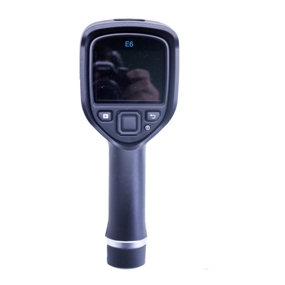
Page 17: Description
Description 6 Description 6.1 Camera parts 6.1.1 Figure 6.1.2 Explanation 1. Digital camera lens. 2. Infrared lens. 3. Lever to open and close the lens cap. 4. Trigger to save images. 5. Battery. #T559828; r. AO/56381/56381; en-US... -
Page 18: Keypad
Description 6.2 Keypad 6.2.1 Figure 6.2.2 Explanation 1. Camera screen. 2. Archive button Function: • Push to open the image archive. 3. Navigation pad. Function: • Push left/right or up/down to navigate in menus, submenus, and dialog boxes. • Push the center to confirm. 4. -
Page 19: Connectors
FLIR power supply or the FLIR stand-alone battery charger. • Moving images from the camera to a computer for further analysis in FLIR Tools. Note Install FLIR Tools on your computer before you move the images. -
Page 20: Operation
To charge the camera, the computer must be turned on. • Charging the camera using a USB cable connected to a computer takes considerably longer than using the FLIR power supply or the FLIR stand-alone battery charger. #T559828; r. AO/56381/56381; en-US... -
Page 21: Turning On And Turning Off The Camera
Operation 7.2 Turning on and turning off the camera • Push the button to turn on the camera. • Push and hold the button for less than 5 seconds to put the camera in standby mode. The camera then automatically turns off after 48 hours. •... -
Page 22: Deleting An Image
Operation 7.5 Deleting an image 7.5.1 General You can delete one or more images from the internal camera memory. 7.5.2 Procedure Follow this procedure: 1. Push the Archive button 2. Push the navigation pad left/right or up/down to select the image you want to view. 3. -
Page 23: Procedure
Operation 7.8.2 Procedure Follow this procedure: 1. Push the center of the navigation pad. This displays a toolbar. 2. On the toolbar, select Measurement . This displays a toolbar. 3. On the toolbar, select Hot spot 7.9 Measuring the coldest temperature within an area 7.9.1 General You can measure the coldest temperature within an area. -
Page 24: Image Examples
Operation 7.12.2 Image examples This table explains the different color alarms (isotherms). Image Color alarm Below alarm Above alarm 7.12.3 Procedure Follow this procedure: 1. Push the center of the navigation pad. This displays a toolbar. 2. On the toolbar, select Color . -
Page 25: Changing Image Mode
Operation 7.13 Changing image mode 7.13.1 General The camera can operate in five different image modes: • Thermal MSX (Multi Spectral Dynamic Imaging): The camera displays an infrared im- age where the edges of the objects are enhanced. • Thermal: The camera displays a fully thermal image. •... -
Page 26: Procedure
Operation • Digital camera: The camera displays a digital camera image. To display a good fusion image (Thermal MSX, Picture-in-picture, and Thermal blending modes), the camera must make adjustments to compensate for the small difference in position between the digital camera lens and the infrared lens. To adjust the image accu- rately, the camera requires the alignment distance (i.e., the distance to the object). -
Page 27: Procedure
Operation Automatic Manual 7.14.2.2 Example 2 Here are two infrared images of an isolator in a power line. To make it easier to analyze the temperature variations in the isolator, the temperature scale in the right image has been changed to values close to the temperature of the isolator. Automatic Manual 7.14.3 Procedure... -
Page 28: Procedure
Operation Note For more information, see section 13 About calibration, page 40. 7.15.2 Procedure Follow this procedure: 1. Push the navigation pad to display the menu system. 2. Select (Settings) and push the navigation pad. This displays the Settings menu. 3. -
Page 29: Changing The Emissivity As A Custom Value
Operation 6. In the list, select the material. 7.18 Changing the emissivity as a custom value 7.18.1 General For very precise measurements, you may need to set the emissivity, instead of selecting a surface property or a custom material. You also need to understand how emissivity and reflectivity affect measurements, rather than just simply selecting a surface property. -
Page 30: Changing The Distance Between The Object And The Camera
Operation 7.20 Changing the distance between the object and the camera 7.20.1 General To measure temperatures accurately, the camera requires the distance between the camera and the object. 7.20.2 Procedure Follow this procedure: 1. Push the center of the navigation pad. This displays a toolbar. 2. -
Page 31: Connecting The Camera To A Wireless Local Area Network (Less Common Use)
Operation 4. Select Wi-Fi and push the center of the navigation pad. 5. Select Share and push the center of the navigation pad. 6. (Optional step.) To display and change the parameters, select Settings and push the center of the navigation pad. •... -
Page 32: Procedure
1. Start FLIR Tools. 2. Start the camera. 3. Connect the camera to the computer using the USB cable. 4. On the Help menu in FLIR Tools, click Check for updates. 5. Follow the on-screen instructions. #T559828; r. AO/56381/56381; en-US... -
Page 33: Mechanical Drawings
Mechanical drawings [See next page] #T559828; r. AO/56381/56381; en-US... -
Page 36: Ce Declaration Of Conformity
CE Declaration of conformity [See next page] #T559828; r. AO/56381/56381; en-US... -
Page 38: Cleaning The Camera
Cleaning the camera 10 Cleaning the camera 10.1 Camera housing, cables, and other items 10.1.1 Liquids Use one of these liquids: • Warm water • A weak detergent solution 10.1.2 Equipment A soft cloth 10.1.3 Procedure Follow this procedure: 1. Soak the cloth in the liquid. 2. -
Page 39: Application Examples
Application examples 11 Application examples 11.1 Moisture & water damage 11.1.1 General It is often possible to detect moisture and water damage in a house by using an infrared camera. This is partly because the damaged area has a different heat conduction prop- erty and partly because it has a different thermal capacity to store heat than the sur- rounding material. -
Page 40: Oxidized Socket
Application examples 11.3 Oxidized socket 11.3.1 General Depending on the type of socket and the environment in which the socket is installed, ox- ides may occur on the socket's contact surfaces. These oxides can lead to locally in- creased resistance when the socket is loaded, which can be seen in an infrared image as local temperature increase. -
Page 41: Insulation Deficiencies
Application examples 11.4 Insulation deficiencies 11.4.1 General Insulation deficiencies may result from insulation losing volume over the course of time and thereby not entirely filling the cavity in a frame wall. An infrared camera allows you to see these insulation deficiencies because they either have a different heat conduction property than sections with correctly installed insulation, and/or show the area where air is penetrating the frame of the building. - Page 42 Application examples #T559828; r. AO/56381/56381; en-US...
-
Page 43: Thermographic Measurement Techniques
Thermographic measurement techniques 12 Thermographic measurement techniques 12.1 Introduction An infrared camera measures and images the emitted infrared radiation from an object. The fact that radiation is a function of object surface temperature makes it possible for the camera to calculate and display this temperature. However, the radiation measured by the camera does not only depend on the tempera- ture of the object but is also a function of the emissivity. - Page 44 Thermographic measurement techniques 12.2.1.1.1 Method 1: Direct method Follow this procedure: 1. Look for possible reflection sources, considering that the incident angle = reflection angle (a = b). Figure 12.1 1 = Reflection source 2. If the reflection source is a spot source, modify the source by obstructing it using a piece if cardboard.
- Page 45 Thermographic measurement techniques 3. Measure the radiation intensity (= apparent temperature) from the reflection source using the following settings: • Emissivity: 1.0 • D You can measure the radiation intensity using one of the following two methods: Figure 12.3 1 = Reflection source Figure 12.4 1 = Reflection source You can not use a thermocouple to measure reflected apparent temperature, because a thermocouple measures temperature, but apparent temperatrure is radiation intensity.
- Page 46 Thermographic measurement techniques 5. Measure the apparent temperature of the aluminum foil and write it down. The foil is considered a perfect reflector, so its apparent temperature equals the reflected appa- rent temperature from the surroundings. Figure 12.5 Measuring the apparent temperature of the aluminum foil. 12.2.1.2 Step 2: Determining the emissivity Follow this procedure: 1.
-
Page 47: Reflected Apparent Temperature
50%. 12.6 Other parameters In addition, some cameras and analysis programs from FLIR Systems allow you to com- pensate for the following parameters: • Atmospheric temperature – i.e. the temperature of the atmosphere between the cam- era and the target •... -
Page 48: About Calibration
13.3 Camera calibration at FLIR Systems Without calibration, an infrared camera would not be able to measure either radiance or temperature. At FLIR Systems, the calibration of uncooled microbolometer cameras with a measurement capability is carried out during both production and service. Cooled cam- eras with photon detectors are often calibrated by the user with special software. -
Page 49: The Differences Between A Calibration Performed By A User And That Performed Directly At Flir Systems
The calibration information, no matter if the calibration is done by FLIR Systems or the user, is stored in calibration curves, which are expressed by mathematical functions. As... -
Page 50: Non-Uniformity Correction
About calibration Calibration is also a prerequisite for adjustment, which is the set of operations carried out on a measuring system such that the system provides prescribed indications corre- sponding to given values of quantities to be measured, typically obtained from measure- ment standards. -
Page 51: About Flir Systems
• Prox Dynamics (2016) Figure 14.1 Patent documents from the early 1960s FLIR Systems has three manufacturing plants in the United States (Portland, OR, Boston, MA, Santa Barbara, CA) and one in Sweden (Stockholm). Since 2007 there is also a manufacturing plant in Tallinn, Estonia. -
Page 52: More Than Just An Infrared Camera
14.1 More than just an infrared camera At FLIR Systems we recognize that our job is to go beyond just producing the best infra- red camera systems. We are committed to enabling all users of our infrared camera sys- tems to work more productively by providing them with the most powerful camera–... -
Page 53: Supporting Our Customers
About FLIR Systems 14.3 Supporting our customers FLIR Systems operates a worldwide service network to keep your camera running at all times. If you discover a problem with your camera, local service centers have all the equipment and expertise to solve it within the shortest possible time. Therefore, there is no need to send your camera to the other side of the world or to talk to someone who does not speak your language. - Page 54 #T559828; r. AO/56381/56381; en-US...
- Page 56 Disclaimer Specifications subject to change without further notice. Models and accessories subject to regional market considerations. License procedures may apply. Products described herein may be subject to US Export Regulations. Please refer to exportquestions@flir.com with any questions. Publ. No.: T559828...
Need help?
Do you have a question about the Ex Series and is the answer not in the manual?
Questions and answers