
Subscribe to Our Youtube Channel
Related Manuals for Toshiba VN-M150HE


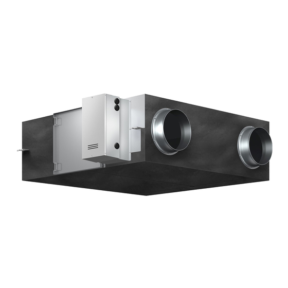
Summary of Contents for Toshiba VN-M150HE
-
Page 1: Service Manual
FILE No. A10-021 Air to Air Heat Exchanger SERVICE MANUAL Concealed microcomputer control type Model name: VN-M150HE VN-M250HE VN-M350HE VN-M500HE VN-M650HE VN-M800HE VN-M1000HE... -
Page 2: Table Of Contents
Contents 1 Features ............10 2 Specifications . -
Page 3: Original Instruction
• The qualified service person is a person who installs, repairs, maintains, relocates and removes the Air to Air Heat Exchanger made by Toshiba Carrier Corporation. He or she has been trained to install, repair, maintain, relocate and remove the Air to Air Heat Exchanger made by Toshiba Carrier... - Page 4 Definition of Protective Gear When the Air to Air Heat Exchanger is to be transported, installed, maintained, repaired or removed, wear protective gloves and ‘safety’ work clothing. In addition to such normal protective gear, wear the protective gear described below when undertaking the special work detailed in the table below.
- Page 5 Warning Indications on the Air to Air Heat Exchanger Unit [Confirmation of warning label on the main unit] Confirm that labels are indicated on the specified positions. If removing the label during parts replace, stick it as the original. Warning indication Description WARNING WARNING...
- Page 6 Precautions for Safety The manufacturer shall not assume any liability for the damage caused by not observing the description of this manual. DANGER Before carrying out the installation, maintenance, repair or removal work, be sure to set the circuit breaker for Air to Air Heat Exchanger to the OFF position.
- Page 7 WARNING Before starting to repair the Air to Air Heat Exchanger, read carefully through the Service Manual, and repair the Air to Air Heat Exchanger by following its instructions. Only qualified service person (*1) is allowed to repair the Air to Air Heat Exchanger. Repair of the Air to Air Heat Exchanger by unqualified person may give rise to a fire, electric shocks, injury, water leaks and/or other problems.
- Page 8 If, in the course of carrying out repairs, it becomes absolutely necessary to check out the electrical parts with the electrical control cover of one or more of the Air to Air Heat Exchanger removed in order to find out exactly where the trouble lies, put a sign in place so that no-one will approach the work location before proceeding with the work.
- Page 9 Relocation • Only a qualified installer (*1) or qualified service person (*1) is allowed to relocate the Air to Air Heat Exchanger. It is dangerous for the Air to Air Heat Exchanger to be relocated by an unqualified individual since a fire, electric shocks, injury, water leakage, noise and/or vibration may result.
- Page 10 VN-M800HE VN-M1000HE Commercial name: TOSHIBA Air to Air Heat Exchanger Complies with the provisions of the “Machinery” Directive (Directive 2006/42/EC) and the regulations transposing into national law. Must not be put into service until the final machinery into which it is to be incorporated has been declared in conformity with the provisions of Machinery Directive, where appropriate.
-
Page 11: Features
Features Main features The ventilation balance of air supplying and air exhausting can be changed. The filter inspection display function calculates the total ◆ Power saving ventilation running time and prompts you through the remote controller to inspect the filter. The cost of cooling and heating is reduced thanks to The cold mode function automatically makes the air the unit efficiently retrieving thermal energy (outdoor... -
Page 12: Specifications
Specifications Concealed microcomputer control type Model No. Item M150HE M250HE M350HE M500HE M650HE M800HE M1000HE Fan Speed Type Concealed type Power Supply (V) Single phase 220-240V~,50Hz 220V~,60Hz 50Hz 68-78 123-138 165-182 214-238 262-290 360-383 532-569 (Extra high) 60Hz Heat 50Hz 59-67 99-111 135-145... - Page 13 Model No. Item M150HE M250HE M350HE M500HE M650HE M800HE M1000HE Fan Speed 50Hz 1000 (Extra high) 60Hz 1000 50Hz 1000 Air Volume (m High 60Hz 1000 50Hz 60Hz 50Hz 82-102 80-98 114-125 134-150 91-107 142-158 130-150 (Extra high) 60Hz Heat 50Hz 52-78 34-65...
- Page 14 Model No. Item M150HE M250HE M350HE M500HE M650HE M800HE M1000HE Fan Speed Frame Zinc steel sheets Motor 4-pole capacitor dielectric motor (E type) PP resin Heat exchanger Special paper + Resin Filter Nonwoven fabric (Collection effect weighing method 82%) Adapter Zinc steel sheets External dimensions (Length x Width x Height) 900 x 900 x 290...
-
Page 15: Model List
Electrical control base Galvanized steel sheet Heat exchange Fire-resistant paper + Air to air heat Fixing lever SUS304 element Resin exchanger Applicable duct Model name nominal diameter VN-M150HE Ø98 Ø110 Ø100 VN-M250HE Ø145 Ø158 Ø150 VN-M350HE Ø145 Ø158 Ø150 VN-M500HE... -
Page 16: Connection Diagram
Connection diagram Gray Light blue External output *5 External input (sold (220-240V~, under 1A each) separately) No voltage a-contact input 43F12 43F11 43F22 43F21 Operation output 1 Common Connector Connector 2 Remote controller operation (White) (Black) Common 3 Ventilation fan speed External damper output White Yellow... -
Page 17: Parts Rating
Parts Rating Model VN-M 150HE 250HE 350HE 500HE 650HE 800HE 1000HE Running condenser for supply air 450V 450V 450V 450V 450V 450V 450V fan motor 10 F (5 F x 2) Running condenser for exhaust 450V 450V 450V 450V 450V 450V 450V air fan motor... -
Page 18: Control Outline
Control Outline Air to Air Heat Exchanger Control Specifications Item Specification outline Remarks When the power 1. If the power supply is reset during the occurrence of an error, the check code is is reset cleared. If an abnormal state continues even after the unit is restarted by pressing the [ON/ OFF] button on the remote controller, the check code is redisplayed on the remote controller. - Page 19 Item Specification outline Remarks Ventilation Automatic ventilation mode control in the Air to Air Heat mode control Exchanger system (continued) Heat Exchange Cooling zone Bypass Fan zone Heat Exchange Bypass Undefined Heating zone zone Undefined Heat Exchange zone RA: Return Air (°C) Start operation Ventilation mode Automatic...
- Page 20 Item Specification outline Remarks Ventilation 2. Air to Air Heat Exchanger system linked with air conditioners mode control 1) Automatic ventilation mode control in the air-conditioning linkage (continued) • Determine the mode from the operation mode of the air conditioner. [Cooling zone]: The air conditioner operation mode is Automatic cooling, Cooling, or Drying mode.
- Page 21 Item Specification outline Remarks Ventilation Heating zone mode control (continued) Maximum set Bypass temperature Undefined zone Heat Exchange RA: Return Air (°C) Start operation Automatic ventilation determination in air conditioning linkage Cooling or Drying mode Cooling zone Heating zone RA, OA RA, OA detection detection...
- Page 22 Item Specification outline Remarks 24-hour 1. 24-hour ventilation operation and setting CODE No. (DN) ventilation • By operating the [ON/OFF] and [VENT] buttons during operation of Air to Air [47][31][49][4A] control Heat Exchangers, they stop operation and the system moves to 24-hour ventilation (low): 60 minutes ON, 60 minutes OFF.
- Page 23 Item Specification outline Remarks Nighttime heat This function is valid only for the Air to Air Heat Exchanger system linked with air CODE No. (DN) purge control conditioners (invalid for the Air to Air Heat Exchanger system). [4C][47] 1. If the [ON/OFF] button is pressed during operation, the Air to Air Heat Exchangers and the air conditioners stop, and the system enters the nighttime heat purge mode (standby mode).
- Page 24 Item Specification outline Remarks Nighttime heat Nighttime heat purge control purge control (continued) Cooling zone Bypass Heat Exchange Minimum set Undefined temperature zone RA: Return Air (°C) Air to Air Heat Exchangers and air conditioners are stopped. 24-hour ventilation setting invalid Start 24-hour ventilation Air to Air Heat Exchanger system linked with air conditioners...
- Page 25 Item Specification outline Remarks Cold mode 1. Even in Bypass mode control, the system automatically enters Heat Exchange CODE No. (DN) control mode to prevent condensation if OA RA/10°C + 12.5°C. [4D] • The display on the remote controller remains “Bypass mode” regardless of the ventilation mode in actual operation.
- Page 26 Item Specification outline Remarks Cold mode Operating control (continued) RA/10°C + 12.5°C Heat Exchange Present ventilation mode continues Zone A? Zone B? Zone C DN [4D] Exhausting fan runs: 0000 Heat Exchange Heat Exchange Supplying fan Heat Exchange Supplying fan Heat Exchange Supplying fan mode continues stops (OFF for 10 minutes and...
- Page 27 Item Specification outline Remarks Selection of 1. The range of operations that can be performed by operating the remote controller • “ ” lights up while central control of the Air to Air Heat Exchanger can be determined through the setting of the in central control mode central controller.
- Page 28 Item Specification outline Remarks Linked Connect the Remote ON/OFF adapter (NRB-1HE: sold separately) to the CODE No. (DN) operation with connectors CN706(2P) and CN705(5P) on the control circuit board of the Air to Air [4E] external devices Heat Exchanger. • Remote ON/OFF 1.
-
Page 29: Applied Control And Functions (Including Circuit Configuration)
Applied Control and Functions (Including Circuit Configuration) 7-1. Heat Exchanger Controller Block Diagram Main (sub) center remote controller Schedule timer (up to 2 units) (when in weekly timer mode) Display Display driver Display Function setting Function setting Key switch Key switch EEPROM DC5V DC5V... - Page 30 7-2. Indoor Printed Circuit Board MCC-1615...
- Page 31 7-3. Functions at Test Operation ◆ Checking ventilation mode test operation Starting and stopping test operation ▼ Performing test operation from the indoor remote controller Wired remote controller Procedure Operation When the button is pushed for 4 seconds or more, “TEST” is displayed in the display section, and the unit enters test operating mode.
- Page 32 ◆ Check function for operation of Air to Air Heat Exchanger This function is provided to check the operation of Air to Air Heat Exchanger singly without communication with the remote controller. This function can be used regardless of operation or stop of the system. However, if using this function for a long time, a trouble of the equipment may be caused.
- Page 33 7-4. Specifications of Optional Connectors on the Air to Air Heat Exchanger Unit Board Function Connector No. Pin No. Specification Note External 0V (COM) input Remote controller Remote controller prohibition input (ON: Prohibited, OFF: No-voltage prohibition input Allowed) contact a Ventilation fan speed Ventilation fan speed change input (ON: LOW, OFF: HIGH) CN705...
- Page 34 7-5. Configuring the Function Settings of the Air to Air Heat Exchanger Unit (When configuring the settings, use the wired remote controller.) <Procedure> Stop running the unit before configuring the settings. Press and hold the buttons for 4 seconds or longer. The Unit No.
- Page 35 Codes (DN codes) for changing settings (Necessary for local advanced control) The following DN codes are used in common for NRC-01HE, RBC-AMT32E, and RBC-AMS41E. Code Description SET DATA and description Factory default Note Lighting-up 0000: None 0002: 2500 H Adjusting this setting is necessary for the hours of the 0001: 150 H header unit.
- Page 36 Code Description SET DATA and description Factory default Note Setting of the 0000: Exhausting fan run 0000: Exhausting fan run Adjusting this setting is necessary for all exhausting fan 0001: Exhausting fan stop the Air to Air Heat Exchangers in the group. operation below * The supplying fan stops when 15°C (OA)
- Page 37 Model Capacity of the Air to Air Heat Exchanger Code: 10 Code: 11 Setting Model name Setting data Type Model data (abbreviation) Air to Air Heat Exchanger 0050* VN-M***HE series 0000* Invalid (Ceiling-embedded) 0001 150m /h type * Factory default value of EEPROM installed on the service 0002 250m /h type...
-
Page 38: Air To Air Heat Exchanger Unit And Air-Conditioning System
Air to Air Heat Exchanger Unit and Air- Conditioning System Examples of connections available when installing an Air to Air Heat Exchanger unit (VN-M OO HE) Classified by specifications Remote controller line * Adapter omitted Indoor unit compatible Indoor unit not yet New Air to Air Heat Old Air to Air Heat TCC-LINK line... - Page 39 Pattern 3 Not Possible Pattern 4 Not Possible Pattern 5 Not Possible Pattern 6 Not Possible...
- Page 40 Pattern 7 Possible Pattern 8 Possible Pattern 9 Possible When linking a unit compatible with Air to Air Heat Exchange to one not yet compatible, you need to set a compatible unit as the group header unit.
- Page 41 List of Indoor Units (SMMS Series) Compatible with the Air to Air Heat Exchanger Unit • “O” in the tables indicates an indoor unit compatible with the Air to Air Heat Exchanger unit. * For the 4-way air discharge type/2-way air discharge type, products produced in September 2010 or later are compatible.
- Page 42 List of Indoor Units (DI, SDI Series) Compatible with Air to Air Heat Exchanger Unit • “O” in the tables indicates an indoor unit compatible with the Air to Air Heat Exchanger unit. * For the 4-way air discharge type/Duct type/Slim duct type, products produced in September 2010 or later are compatible.
- Page 43 Air to Air Heat Exchanger Unit and (SMMS Series) Air-Conditioning System System Central control Address Air to Air Heat Exchanger only Linked with air-conditioner Outdoor Outdoor unit unit U1 U2 U1 U2 U1 U2 U1 U2 U1 U2 U1 U2 Indoor Indoor Air to Air Heat...
- Page 44 Air to Air Heat Exchanger Unit and (DI, SDI Series) Air-Conditioning System System Central control Address Air to Air Heat Exchanger only Linked with air-conditioner Outdoor Outdoor unit unit 1 2 3 1 2 3 1 2 3 1 2 3 Indoor Indoor Air to Air Heat...
-
Page 45: Failure Diagnosis
Failure Diagnosis 9-1. Failure Diagnosis 9-1-1. Before diagnosing failure Symptom Cause • Is the circuit breaker turned off? • Has a power failure occurred? Operation does not start after pressing • Does the indicator light up? the button. (The ventilation delay setting is set to CODE No. [49] “ON” and it is not malfunction. - Page 46 9-2. How to Check for Errors The remote controller (local remote controller or central control) is equipped with an LCD that displays the operation status. If an error has occurred, see the following table to check the error of the Air to Air Heat Exchanger unit using the failure diagnosis function.
- Page 47 9-3. Troubleshooting • [01: Order of error history] is displayed in CODE No. window. • [Check code] is displayed in CHECK window. • [Air to Air Heat Exchanger address in which an Confirmation and check error occurred] is displayed in Unit No. * Unit No.
- Page 48 TCC Link Central Control Remote Controller (TCB-SC642TLE2) (1) Checking and testing If an error has occurred in the Air to Air Heat Exchanger, the check code and the unit No. of the Air to Air Heat Exchanger appear on the display of the remote controller. Unit No.
- Page 49 9-4. Check Codes Displayed on the Remote Controller and Locations to Be Checked Check code Location Check code Error detection System status Items to check (locations) Remote name conditions detection controller Remote Indoor–remote Stop of Communication between • Check remote controller inter-unit tie cable controller controller corresponding...
-
Page 50: Errors Detected By Tcc-Link Central Control Device
Check code Location Check code Error detection System status Items to check (locations) Remote name conditions detection controller Indoor Duplicate central Stop of Duplicate central control • Check central control addresses. control address corresponding address • Check network adapter PC board unit only (applicable to AI-NET). -
Page 51: Sensor Characteristics
9-5. Sensor Characteristics Air to Air Heat Exchanger ▼ Temperature Sensor Characteristics Characteristic 1 Characteristic 2 Return air temperature Outdoor air temperature sensor (TRA) sensor (TOA) Resistance Resistance (k ) (k ) (10°C or (10°C or less) more) -1 0 Temperature (°C) Temperature (°C) -
Page 52: Exchanging And Assembling The Main Components
Exchanging and Assembling the Main Components Assembling and exchanging the fan components Component Procedure Note Inspection cover (LID, 1. Remove the machine screws (M4×12) that fix the Machine screws (M4×12) SERVICE) inspection cover (LID, SERVICE), pull up the 1, 15, 16 lever (LEVER, LID), then remove the cover. - Page 53 Component Procedure Note Electrical control cover 5. Remove the four screws (M4×6) that fix the Screws (M4×6) (COVER, PC BOARD) electrical control cover (COVER, PC BOARD), then remove the cover. Electrical control cover (COVER, BOARD) Screws (M4×6) Connector of MOTOR 6.
- Page 54 Component Procedure Note Fan (FAN) 8. Release the big clamp (CLAMP) that fixes the Exhaust motor Supply motor 1 - 10 cords of the supply motor (MOTOR, SUPPLY) (MOTOR, EXHAUST) (MOTOR, SUPPLY) and exhaust motor (MOTOR, EXHAUST). Big clamp (CLAMP) Release 9.
- Page 55 Component Procedure Note Supply motor (MOTOR, 11.Remove the screws that fix the supply motor 800/1000 type SUPPLY) (MOTOR, SUPPLY), then remove the motor. 1 - 6, Hexagon head Motor holder 8 - 11 screws (M8×16) (HOLDER, MOTOR) Exhaust motor (MOTOR, 12.Remove the screws that fix the exhaust motor 150 –...
- Page 56 Component Procedure Note Exhaust casing (CASE 14.Pull the exhaust casing (CASE ASSY, Exhaust casing (CASE ASSY, EXHAUST) EXHAUST) to the former location of the foam ASSY, EXHAUST) 1 - 4, 14 cover (COVER, FOAM), pull the bottom toward you, then turn it horizontally to pull it out. Coupling (COUPLING) 15.Remove the screws (M4×6) that fix the coupling Inspection cover...
- Page 57 Component Procedure Note Fixing lever (LEVER, 18.Widen the fixing lever (LEVER, LID) to remove it LID) from the gutter. 1, 18 Inspection cover (LID, SERVICE) Fixing lever (LEVER, LID) Damper motor holder 19.Release the small clamp (CLAMP) and big clamp (STAY, DAMPER (CLAMP) that fix the connector (CONNECTOR, MOTOR)
- Page 58 Component Procedure Note Electrical control base 24.Disconnect all the connectors from the PC board Electrical control (LID, ELECTRIC (PC BOARD). base PARTS) Thread all the connectors through the cord (LID, ELECTRIC PARTS) Tapping (SCREW, bushes. : Connectors TAPPING) 5, 24, 25, 26 Cord bush 25.Remove the two tapping screws (SCREW, Tapping screws...
- Page 59 Component Procedure Note PC board (PC BOARD) 26.Remove the screws (M4×6) that fix the earth wire. Squeeze the stopper 5, 24, 26 Remove the six spacers from the PC board (PC to remove BOARD). : Spacer (SPACER) Screws (M4×6) Earth wire Spacer (SPACER) 27.Squeeze the lock of the spacer (SPACER) to...
- Page 60 Component Procedure Note Communication wire 30.Pull out the fastening terminal of the connector Pull out the terminal block (CONNECTOR, 8). fastening terminals (TERMINAL, 4P) Remove the two screws that fix the 5, 30 communication wire terminal block (TERMINAL, 4P), then remove the communication wire terminal block.
- Page 61 Component Procedure Note Connector 34.Cut the cable tie that fixes the connector (CONNECTOR, 1 - 9) (CONNECTOR, 1 - 9), then pull out the fastening CONNECTOR, 1 5, 34 terminals of the connectors. Note: When cutting the cable tie, be careful not to cut the CONNECTOR, 5 lead wire unintentionally.
- Page 62 Component Procedure Note Connector 3 37.Pull out the fastening terminal of the relay (CONNECTOR, 3) (RELAY, LY-1F). 5, 37, 45 Connector 4 38.Pull out the fastening terminal of the relay (CONNECTOR, 4) (RELAY, LY-1F). 5, 34, 38, 45 Remove the connector of the PC board (PC BOARD).
- Page 63 Component Procedure Note Capacitor 44.Pull out the fastening terminal of the connector Screws (CAPACITOR) (CONNECTOR, 1). (M4×14) 5, 44 Remove the screw (M4×14) that fixes the capacitor (CAPACITOR), then remove the CONNECTOR, 1 capacitor. Relay (RELAY, LY-1F) 45.Pull out the fastening terminals of the connectors 5, 45 (CONNECTOR, 1 -4, 6).
-
Page 64: Owner's Manual
Owner’s Manual Original instruction Thank you very much for purchasing TOSHIBA Air to Air Heat Exchanger. Please read this owner’s manual carefully before using your Air to Air Heat Exchanger. • Obtain the “Owner’s manual” and “Installation manual” from constructor (or dealer). - Page 65 Exchangers made by Toshiba Carrier Corporation. He or she has been trained to install, maintain, relocate and remove the Air to Air Heat Exchangers made by Toshiba Carrier Corporation or, alternatively, he or she has been instructed in such operations by an individual or individuals who have been trained and is thus thoroughly acquainted with the knowledge related to these operations.
- Page 66 Warning indications on the Air to Air Heat Exchanger Warning indication Description WARNING WARNING ELECTRICAL SHOCK HAZARD ELECTRICAL SHOCK HAZARD Disconnect all remote Disconnect all remote electric power supplies before servicing. electric power supplies before servicing. WARNING WARNING Moving parts. Moving parts.
-
Page 67: Precautions For Safety
Precautions for Safety WARNING General • Carefully read Owner’s Manual before starting the Air to Air Heat Exchanger. There are many important things to keep in mind for daily operation. • Ask for installation to be performed by the dealer or a professional. Only a qualified installer (*1) is able to install an Air to Air Heat Exchanger. - Page 68 • If there is a danger of the Air to Air Heat Exchanger’s falling, do not approach the Air to Air Heat Exchanger but set the circuit breaker to the OFF position, and contact a qualified installer or a qualified service person to refit the unit. Do not set the circuit breaker to the ON position until the unit has been refitted.
- Page 69 Information on the transportation, handling and storage of the carton Examples of indication on the carton Symbol Description Symbol Description Keep dry Do not drop Stacking height 2 cartons Do not lay down (3 cartons can be stacked in this case) This side up Do not step...
-
Page 70: Features
Features Main features About ventilation modes The unit has three ventilation modes. ◆ Power saving ventilation • Heat exchange mode Exchanging heat between the outdoor and indoor air The cost of cooling and heating is reduced thanks to and making the temperature and humidity of the the unit efficiently retrieving thermal energy (outdoor outdoor air closer to those of the indoor air before air load) which has been lost during ordinary... -
Page 71: Standard Installation Example
Standard Installation Example Concealed microcomputer control type Hanging bolt Pipe hood Outdoor air intake duct Supply air duct SA (Supply air) RA (Return air) Heat insulation material Return air intake duct OA (Outdoor air) Indoor supply opening EA (Exhaust air) (Supply/Exhaust Air grille) Room intake Exhaust air... -
Page 72: System Configuration
System Configuration The control method of this product differs depending on the system configuration. Operate it following the methods explained in the system configuration examples below. • For the actual system configuration, ask your dealer or the installer of the product for information. •... - Page 73 System example Operation Cautions If three control devices C. Central control system • The central controller can be (When controlling the air conditioner group and the Air to Air used to start/stop the whole are used; the central Heat Exchanger group separately) system and separately start/stop controller and the groups of air conditioners and...
-
Page 74: Part Names And Functions
(Outdoor air) (Supply air) Inspection cover Fixing bracket Fixing lever High efficiency filter (One for each element) Filter (Two for (sold separately) each element) Unit: mm Model Model VN-M150HE VN-M650HE 1140 1140 VN-M250HE VN-M800HE 1189 1189 VN-M350HE VN-M1000HE 1189 1189... -
Page 75: Operation Section
Remote controller for the Air to Air Heat Exchanger NRC-01HE ◆ Operation section • One of these remote controllers can be used to control both indoor air conditioner units and Air to Air Heat Exchangers (up to 8 units in total). Display •... - Page 76 UNIT LOUVER button (Unit/Louver select button) button (Ventilation mode button) Used for selecting a unit while changing settings if Used to select a ventilation mode. the remote controls two or more units. button (Filter elevating button) (*1) UNIT button: * This function is not available. If two or more indoor units are controlled by one remote controller, use this button to select a unit to adjust its air blow direction.
- Page 77 ◆ Display section All indicators are displayed on the display example below for explanation. In reality, only the selected options will be displayed. Indications concerning Display controlling the Air to Air Heat Exchanger are explained here. For indications section concerning an air conditioner, refer to the owner's manuals supplied with the air conditioner.
- Page 78 15 17 Remote controller sensor indicator (*1) device prohibits the use of local remote controllers, blinks when any of the Displayed when the remote controller sensor is or TEMP. buttons are pressed and the used. operation is rejected. Pre-heat indicator (*1) The items controllable with the remote differ Displayed when the heating mode is energized or depending on the mode of central control.
- Page 79 Operation ready display (*1) Ventilation on-standby indicator This display appears on some models. Displayed while the Air to Air Heat Exchanger is on standby. While this indicator is displayed, the Air to Service display Air Heat Exchanger is not in operation. Displayed while the protective device works or a * Displayed when the setting is activated.
-
Page 80: How To Use
How to Use When using the remote controller for the Air to Air Heat Exchanger (NRC-01HE) When the Air to Air Heat Exchanger is used for the first time or change the settings, operate the remote following the procedure below. From the next time, the unit starts running following the set operation conditions by just pressing the button. - Page 81 About the separate operation Functions of the Air to Air Heat About ventilation modes Exchanger in an Air to Air * For details, see “About ventilation modes” on page Heat Exchanger system [Heat exchange mode], [Bypass mode] or linked with air conditioners [Automatic mode] can be selected.
- Page 82 About nighttime heat purge operation The conditions to start the nighttime heat purge • Nighttime heat purge is a function to reduce the operation room air conditioning load in the morning in The unit compares temperatures indoor and outdoor summer by exhausting the air indoor which has using the monitoring operation (for about 5 minutes) become warm while the air conditioner is and will start the nighttime heat purge operation if the...
-
Page 83: Timer Operation
Timer Operation Select a timer type from the following three: (Max. 168 hours) OFF timer : Stops running after a specified period. Repeat-OFF timer : Stops running after a specified period every time the unit is used. On timer : Starts running after a specified period. Setting the timer Push the button to start operation. -
Page 84: Maintenance
Maintenance Maintenance of the filter and heat exchange element WARNING Cleaning the filter and heat exchange element involves dangerous work in high places, have a qualified installer or qualified service person to do it. Do not attempt it by yourself. CAUTION Do not push buttons with wet hands. -
Page 85: Specifications
Specifications Concealed microcomputer control type Model No. Item M150HE M250HE M350HE M500HE M650HE M800HE M1000HE Fan Speed Power Supply (V) Single phase 220-240V~,50Hz 220V~,60Hz 50Hz 68-78 123-138 165-182 214-238 262-290 360-383 532-569 (Extra high) 60Hz Heat 50Hz 59-67 99-111 135-145 176-192 240-258 339-353... - Page 86 Model No. Item M150HE M250HE M350HE M500HE M650HE M800HE M1000HE Fan Speed 50Hz 1000 (Extra high) 60Hz 1000 50Hz 1000 Air Volume (m High 60Hz 1000 50Hz 60Hz 50Hz 82-102 80-98 114-125 134-150 91-107 142-158 130-150 (Extra high) 60Hz Heat 50Hz 52-78 34-65...
- Page 87 Model No. Item M150HE M250HE M350HE M500HE M650HE M800HE M1000HE Fan Speed External dimensions (Length x Width x Height) (mm) 900 x 900 x 290 1140 x 1140 x 350 1189 x 1189 x 400 Product weight (kg) Applicable duct nominal diameter (mm) Ø100 Ø150 Ø200...
-
Page 88: Before Calling For Service
Before Calling for Service Check the points described below before asking for repair servicing. Symptom Cause • Is the circuit breaker turned off? • Has a power failure occurred? Operation does not start after pressing • Does the indicator light up? the button. -
Page 89: Troubleshooting
Troubleshooting CAUTION If any of the following conditions occur, turn off the main power supply switch and immediately contact the dealer: • Switch operation does not work properly. • The main power fuse often blows out, or the circuit breaker is often activated. •... - Page 90 • For additional information, please contact the municipal facility, the shop/dealer/installer that sold the product, or the producer. Country Name of Company responsible for WEEE. AIRCOND, Klimaanlagen GT Phelan Unit 30 Southern Toshiba Carrier UK Ltd Handelsgesellshcaft m.b.H Ireland Cross Business Park Bray Co Porsham Close, Belliver Ind.
- Page 91 VN-M800HE VN-M1000HE Commercial name: TOSHIBA Air to Air Heat Exchanger Complies with the provisions of the “Machinery” Directive (Directive 2006/42/EC) and the regulations transposing into national law. Must not be put into service until the final machinery into which it is to be incorporated has been declared in conformity with the provisions of Machinery Directive, where appropriate.
-
Page 92: Installation Manual
Request to constructor or dealer • Please clearly explain the contents of the Owner’s manual and hand over it. • Read this Installation Manual thoroughly to fully understand everything about your Toshiba Air to Air Heat Exchanger and be able to install it properly. - Page 93 • The qualified service person is a person who installs, repairs, maintains, relocates and removes the person Air to Air Heat Exchanger made by Toshiba Carrier Corporation. He or she has been trained to install, repair, maintain, relocate and remove the Air to Air Heat Exchanger made by Toshiba Carrier...
- Page 94 Definition of Protective Gear When the Air to Air Heat Exchanger is to be transported, installed, maintained, repaired or removed, wear protective gloves and ‘safety’ work clothing. In addition to such normal protective gear, wear the protective gear described below when undertaking the special work detailed in the table below.
-
Page 95: Precautions For Safety
Air to Air Heat Exchanger is installed by an unqualified individual, a fire, electric shocks, injury, water leakage, noise and/or vibration may result. • If using separately sold products, make sure to use Toshiba specified products only. Using unspecified products may cause fire, electric shock, water leak or other failure. -
Page 96: Electrical Wiring
Electrical wiring • Only a qualified installer(*1) or qualified service person(*1) is allowed to carry out the electrical work of the Air to Air Heat Exchanger. Under no circumstances must this work be done by an unqualified individual since failure to carry out the work properly may result in electric shocks and/or electrical leaks. - Page 97 • The external air intake opening should be positioned away from the exhaust openings of combustion gases. The intake of such gases could cause a lack of oxygen in the room. The external air intake opening should not be positioned where discharged air may directly enter it. A situation like this will lead to the room being contaminated and this may pose a health risk.
-
Page 98: Accessory Parts
Inspection Opening 450 × 450 For the inspection of Filters, or more Heat Exchange Elements, Fans, Motors and Damper. Heat exchange Model No. A (mm) B (mm) C (mm) Weight (kg) element VN-M150HE, M250HE VN-M350HE VN-M500HE, M650HE 1140 1140 VN-M800HE, M1000HE 1189 1189... - Page 99 • Helmet must be worn to protect your head from falling objects. Especially, when you work under an inspection opening, helmet must be worn to protect your head from falling objects from the opening. • Observe the following conditions when using the Air to Air Heat Exchanger. Installation requirements Temperature range 10°C to +40°C, relative humidity 80% or less Outdoor air conditions...
-
Page 100: Separately Sold Parts
Separately Sold Parts • Wired remote controller (for the Air to Air Heat Exchanger) NRC-01HE (Sold separately) Up to 8 units of the Air to Air Heat Exchanger can be operated using this remote controller. Reference Diagram Hanging bolt Pipe hood Outdoor air intake duct Supply air duct... -
Page 101: Model List
Filter (x 2) Electrical control cover Inspection cover High efficiency filter Fixing lever (One for each element) (sold separately) Unit: mm Applicable Model name duct nominal diameter VN-M150HE Ø98 Ø110 Ø121 Ø100 VN-M250HE Ø145 Ø158 Ø162 Ø150 VN-M350HE Ø145 Ø158 Ø162... -
Page 102: Installation
Installation Attaching the adapter Model name Weight (kg) Hanging bolt • Attach the adapter to the unit using the accessory VN-M150HE screws (4 or 6). VN-M250HE VN-M350HE VN-M500HE M10, M12 Screws (accessory: VN-M650HE 4 or 6 screws) Adapter VN-M800HE VN-M1000HE... - Page 103 Duct Installation • Duct installation is necessary to protect against access to live parts, rain water or contact with moving parts. • Seal the junction of an adaptor and a duct with an aluminium tape firmly to prevent any air leakage. •...
-
Page 104: Electric Wiring
Electric Wiring WARNING 1. Using the specified wires, ensure to connect the wires, and fix wires securely so that the external tension to the wires do not affect the connecting part of the terminals. Incomplete connection or fixation may cause a fire or other troubles. 2. -
Page 105: Remote Controller Wiring
Communication wire Item Communication wire Central control wire (*2) Remote controller wire Model name VN- 2-core, non-polarity Shielded wire 2-core, non-polarity Air to Air Heat M150HE to Exchanger M1000HE (Up to 1000m) 1.25 mm 0.5 mm to 2.0 mm (Up to 2000m) 2.0 mm •... - Page 106 Connection diagram Gray Light blue External output *5 External input (sold (220-240V~, under 1A each) separately) No voltage a-contact input 43F12 43F11 43F22 43F21 Operation output Connector Connector 1 Common 2 Remote controller operation (White) (Black) Common 3 Ventilation fan speed External damper output White Yellow...
- Page 107 Switches and connectors on the circuit board Remove the 4 screws to detach the electrical control cover. * Refer to “9 Installation Method for Each System Configuration” on page 109 about setting the switch. Electrical control base Screws (x 4) Electrical control cover Changeover switch for the terminator...
-
Page 108: Wire Connection
Wire connection In a central control system, connect the copper braid shield of central control wire (2-core shielded wire). Remote Communication wire controller wire terminal block Wiring for the central control (U3, U4) Wiring for the remote Central control controller (A, B) wire Earth screw Power supply terminal... -
Page 109: Wiring Diagram
Switching between Extra High and High WARNING • Turn off the circuit breaker before switching between Extra High and High. When switching to Extra High, connect the black lead wire (Extra High) to the connector. * The blue lead wire (High) is connected as factory default. * Connect the black lead wire both to the supplying air motor (white connector) and the exhausting air motor (red connector). -
Page 110: Installation Method For Each System Configuration
Installation Method for Each System Configuration Settings and electric wiring differ depending on the system configuration. Perform electric wring according to the system examples shown in the table below. (Refer to page 114 to 118 for details.) System example Operation Air to Air Heat Exchanger system •... - Page 111 System example Operation Central control system • The central controller can be used to ON/OFF the whole system and separately ON/OFF groups of the Air to Air (When controlling the Air to Air Heat Exchanger only) Heat Exchangers. Central controller for 64/128 units/groups •...
- Page 112 Air to Air Heat Exchanger system linked Air to Air Heat Exchanger system with air conditioners System example — Central control None No. of Air to Air Heat Multiple Multiple Exchangers Operation together with the air conditioners Remote controller inter-unit Not necessary Necessary wiring...
- Page 113 Central control system System example — — Central control One Air to Air When controlling the air conditioner When controlling the air conditioner Heat Exchanger and the Air to Air Heat Exchanger and Air to Air Heat Exchanger is used. separately together No.
- Page 114 Changing the group address, indoor unit address, and central control address ◆ About the switches on the circuit board of the Air to Air Heat Exchanger SW702 SW703 Changing the group address Header (Individual): ON Follower: OFF Changing the indoor unit address •...
- Page 115 Installing two remote controllers for the Air to Air Heat Exchanger For details on how to install the remote controller for the Air to Air Heat Exchanger, refer to the Installation Manual accessory with the remote controller. One or multiple Air to Air Heat Exchanger(s) can be controlled by using two remote controllers. (Up to two remote controllers can be installed.) Remote controller (inside of the back)
- Page 116 Air to Air Heat Exchanger system (Multiple Air to Air Heat Exchangers are used.) Air to Air Heat Exchanger Air to Air Heat Exchanger Air to Air Heat Exchanger Earth Earth Earth Power supply Power supply Power supply Remote controller Remote controller Remote controller inter-unit wiring...
- Page 117 Central control system (When controlling the Air to Air Heat Exchanger only) For the settings of the central control address, refer to the Installation Manual of the central control device. Power supply Central controller Central control wiring Air to Air Heat Air to Air Heat Air to Air Heat Air to Air Heat...
- Page 118 Central control system (When controlling the air conditioner and the Air to Air Heat Exchanger separately) For the settings of the central control address, refer to the Installation Manual of the central control device. Power supply Power supply Outdoor unit Central controller L1 L2 L3 N Central...
- Page 119 Central control system (When controlling the air conditioner and Air to Air Heat Exchanger together) • For the settings of the central control address, refer to the Installation Manual of the central control device. • Do not perform the central control wiring with the Air to Air Heat Exchanger. Power supply Power supply Outdoor unit...
-
Page 120: Advanced System
Advanced System WARNING • Use wiring that meets the specifications in the Installation Manual and the stipulations in the local regulations and laws. Use of wiring which does not meet the specifications may give rise to electric shocks, electrical leakage, smoking and/or a fire. - Page 121 2) When the output signal of the external device is a no voltage a-contact (static signal) Remote ON/OFF Adapter NRB-1HE (locally procured) CN705 (1), (5) No voltage Green (1) a-contact Yellow (2) Red (3) White (4) Black (5) Control circuit board of the Air to Air Heat Exchanger As these terminals are not used, insulate them.
- Page 122 1) When switching the remote controller between invalid/valid from an external device Remote ON/OFF Adapter NRB-1HE (locally procured) CN705 (1), (2) No voltage Green (1) a-contact Yellow (2) Red (3) The remote controller is White (4) inoperable when SW1 is closed.
- Page 123 3) When switching between Bypass mode/Heat exchange ventilation from an external device Remote ON/OFF Adapter NRB-1HE (locally procured) CN705 (1), (4) Green (1) No voltage a-contact Yellow (2) Red (3) White (4) Bypass mode is applied when SW3 Black (5) is closed, and Heat exchange Control circuit board of the ventilation when it is open.
- Page 124 Connecting an electric damper (electric shutter) (External Output) 220-240V~, 50Hz 220V~, 60Hz Power supply Electric damper If external output is used working at a higher voltage and current than the rated values, install Contact a relay according to the diagram above (diagram for connecting an auxiliary fan).
-
Page 125: Advanced Control
Advanced Control REQUIREMENT • When the unit is used for the first time, it takes a while for the remote controller to recognize operation input after the power is turned on. This is not a malfunction. • For details on the auto address setting of air conditioners when operating together with a SMMS series air conditioner (adjust the auto address setting on the circuit board of the outdoor interface), refer to... - Page 126 Using TIMER time buttons, select SET DATA [ Push button. When the display changes from flashing to lit, the setup is completed. • To change settings of another indoor unit, repeat from Procedure • To change other settings of the selected indoor unit, repeat from Procedure button to clear the settings.
- Page 127 Codes (DN codes) for changing settings Codes in the table below are necessary for local advanced control. Code Description SET DATA and description Factory default Note Lighting-up hours of 0000: None 0002: 2500 H Adjusting this setting is the Filter Sign necessary for the 0001: 150 H header unit.
- Page 128 Code Description SET DATA and description Factory default Note Changing the 0000: ON during normal operation 0000: ON during Adjusting this setting is operation output normal necessary for a Air to 0001: ON during normal operation, 24- operation Air Heat Exchanger hour ventilation, or nighttime heat which transfers the purge operation...
- Page 129 Setting of the Air to Air Heat Exchanger single operation (Setting for the header air conditioner) Single operation of the Air to Air Heat Exchanger is possible when operation of the Air to Air Heat Exchanger is linked with that of the air conditioners. Use the button of the wired remote controller.
- Page 130 Setting of delayed operation (Delayed operation of the Air to Air Heat Exchanger when it operates link with air conditioners) The operation of the Air to Air Heat Exchanger is delayed by [Setting value] x 10 minutes (10 to 60 minutes) when the [ON/OFF] button is pressed.
-
Page 131: Ventilation Mode Setting
Setting for linked operation with external devices Specifies the operation of the Air to Air Heat Exchanger linked with the on/off operation of external devices * For group operation, adjust this setting for the Air to Air Heat Exchanger to which the Remote ON/OFF Adapter (NRB-1HE: sold separately) is connected. - Page 132 Setting for changing the operation output Terminals 1 and 2 for external devices can be used to connect an auxiliary fan or to use the operation output for operating external devices connected to the terminal. It can be specified when the operation output is used. * Apply this setting for the Air to Air Heat Exchanger to which an external device is connected.
- Page 133 Remote controller switch monitoring function This function is available to call the service monitor mode from the remote controller during a test run to acquire temperatures of sensors of indoor unit (Air to Air Heat Exchanger). Push buttons simultaneously for at least 4 seconds to call the service monitor mode.
-
Page 134: Test Run
Test Run Before performing a test run • Before turning on the power supply, carry out the following procedure. Using 500 V-megger, check that resistance of 1 M or more exists between the terminal block of the power supply and the earth (earthing). If resistance of less than 1 M is detected, do not run the unit. -
Page 135: Maintenance
CAUTION The table below shows the weight of each heat exchange element. Handle the heat exchange element carefully so as not to drop it. Model name Weight (kg/unit) Quantity VN-M150HE VN-M250HE VN-M350HE VN-M500HE VN-M650HE VN-M800HE VN-M1000HE Clean the filter if is indicated on the remote controller. - Page 136 Maintenance of the heat Remove the filters. Remove the filters from the frame of the heat exchange elements (Clean exchange element. the heat exchange elements Heat exchange once or twice in 2 years.) elements Clean the heat exchange elements Remove the dust on the surface of the heat exchange element using a vacuum cleaner.
- Page 137 Attach the heat exchange elements. Install the heat exchange elements as before. Filters NOTE Attach the filters. If this unit is used without them, the heat exchange elements will become clogged and a breakdown may result. Attach the inspection cover. Fit the fixing lever to the inspection cover to attach it securely and fix the fixed part of Inspection cover with a screw.
-
Page 138: Troubleshooting
Troubleshooting Confirmation and check When an error occurred in the Air to Air Heat Exchanger, the check code and the unit No. of Air to Air Heat Exchanger appear on the display part of the remote controller. Every pushing of button used to set The check code is only displayed during the operation. - Page 139 Check codes and parts to be checked Wired remote Judging controller Main defective parts Parts to be checked / error description device display No header remote Remote Incorrect remote controller setting --- The header remote controller controller controller has not been set (including two remote controllers). Remote controller No signal can be received from the indoor unit.
-
Page 140: How To Replace The Pc Board For Service On The Air To Air Heat Exchanger
How to replace the PC board for service on the Air to Air Heat Exchanger <Model> 411-75-190 VN-M**HE series (MCC-1615) Note for replacing the PC board for service on the Air to Air Heat Exchanger Before replacing the PC board on the Air to Air Heat Exchanger, non-volatile memory (hereinafter referred to as EEPROM (IC503)) on it stores the important data such as the model code, the capacity code (factory default), the group address, and the 24-hour ventilation settings set automatically or manually (when installing the unit). - Page 141 *1 Readout of the setup data from the *2 Replacing the PC board for service EEPROM Replace the PC board with the one for service. (Read both the setting data adjusted locally and the factory Apply the settings of the changeover switches (SW701, default setting data.) SW702, SW703, and SW301) as before to the PC board for service.
- Page 142 *3 Writing-in of the setup data on the Use the buttons to change the code (DN). Compare the setup data as in step 7. Change the setup data EEPROM according to the notes recorded before replacing the PC board. (Setting data on the EEPROM of the PC board for service is as •...
- Page 143 Notes for the setting items (Code list: Example) Item Memo Factory default Lighting-up hours of the Filter Sign 0002: 2500H Extent of filter clogging 0000: Normal Central control address 0099: Unfixed 0050: Air to Air Heat Exchanger (Ceiling- Model code embedded duct) Capacity code Depending on the capacity...
-
Page 144: Exploded Diagram/Parts List
Exploded Diagram/Parts List VN-M150HE, VN-M250HE, VN-M350HE, VN-M500HE, VN-M650HE 014 015 023 025 029 031 014 015 007 008 005 006 018 019... - Page 145 Q’ty/Set Ref. Part No. Description VN-M150HE VN-M250HE VN-M350HE VN-M500HE VN-M650HE 41112642 HOLDER, LID 41112643 LEVER, LID 41112644 COUPLING 41118427 SCREW, TAPPING 41118646 DAMPER 41118647 DAMPER 41119474 HEAT EXCHANGER 41119475 HEAT EXCHANGER 4111A534 HOLDER, MOTOR 4111A569 CASE ASSY, EXHAUST 4111A570 CASE ASSY, EXHAUST...
- Page 146 Q’ty/Set Ref. Part No. Description VN-M150HE VN-M250HE VN-M350HE VN-M500HE VN-M650HE 41179575 BUSHING 41179576 LID, ELECTRIC PARTS 41179577 BOX, ELECTRIC PARTS 41179585 COVER, PC BOARD 41179579 COVER, WIRE 41179586 SENSOR, TOA 41179587 SENSOR, TRA 41179582 SPACER 41179589 SENSOR, TRA 41179588 SENSOR, TOA...
- Page 147 VN-M800HE, VN-M1000HE 016 018...
- Page 148 Q’ty/Set Ref. Part No. Description VN-M800HE VN-M1000HE 41112642 HOLDER, LID 41112643 LEVER, LID 41112644 COUPLING 41118427 SCREW, TAPPING 41118615 HOLDER, MOTOR 41118648 DAMPER 41119476 HEAT EXCHANGER 4111A571 CASE ASSY, EXHAUST 4111A573 STAY, DAMPER MOTOR 4111A576 COVER, FOAM 4111A585 LID, SERVICE 4111A582 RAIL 41120537...
- Page 149 Q’ty/Set Ref. Part No. Description VN-M800HE VN-M1000HE 43160569 TERMINAL BLOCK, 5P 4118S738 DISK...
Need help?
Do you have a question about the VN-M150HE and is the answer not in the manual?
Questions and answers