Table of Contents
Advertisement
INSTALLATION MANUAL
AIR CONDITIONER (SPLIT TYPE)
Scan QR CODE to access installation and owner's manual on website.
https://www.toshiba-carrier.co.th/manuals/default.aspx
Manual are available in AR/BG/CZ/DA/DE/EL/EN/ES/ET/FI/FR/
HR/HU/IT/LT/LV/NL/NO/PL/PT/RO/RU/SK/SL/SV.
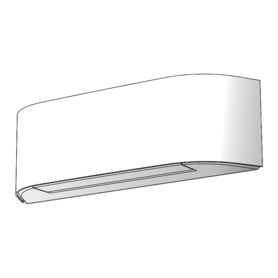
Indoor unit
RAS-B10N4KVRG-E1
RAS-B13N4KVRG-E
RAS-B16N4KVRG-E
Outdoor unit
RAS-10J2AVSG-E1
RAS-13J2AVSG-E1
RAS-16J2AVSG-E1
R32 or R410A
ENGLISH
1129850116A
Advertisement
Table of Contents

Subscribe to Our Youtube Channel
Related Manuals for Toshiba RAS-B10N4KVRG-E1


Summary of Contents for Toshiba RAS-B10N4KVRG-E1
- Page 1 R32 or R410A INSTALLATION MANUAL ENGLISH AIR CONDITIONER (SPLIT TYPE) Scan QR CODE to access installation and owner’s manual on website. https://www.toshiba-carrier.co.th/manuals/default.aspx Manual are available in AR/BG/CZ/DA/DE/EL/EN/ES/ET/FI/FR/ HR/HU/IT/LT/LV/NL/NO/PL/PT/RO/RU/SK/SL/SV. Indoor unit RAS-B10N4KVRG-E1 RAS-B13N4KVRG-E RAS-B16N4KVRG-E Outdoor unit RAS-10J2AVSG-E1 RAS-13J2AVSG-E1 RAS-16J2AVSG-E1 1129850116A...
-
Page 2: Accessory And Installation Parts
Part name Installation plate × 1 Wireless remote controller × 1 Battery × 2 Remote controller holder × 1 Toshiba Ultra pure × 2 Mounting screw × 10 Flat head wood screw × 2 Screw × 2 Owner’s Manual × 1 Installation Manual ×... -
Page 3: Installation Diagram Of Indoor And Outdoor Units
If it is necessary to drain the defrost water, attach drain nipple % and cap Refrigerant piping water proof & to the bottom plate of the outdoor unit before installing it. Liquid side : Ø6.35 mm Gas side : Ø9.52 mm (RAS-B10N4KVRG-E1) each (RAS-B13N4KVRG-E) : Ø12.70 mm (RAS-B16N4KVRG-E) Pipe insulating material... -
Page 4: Indoor Unit
INDOOR UNIT Space allows under the indoor unit Installation Place Space allows for moving range of the air inlet grille and horizontal louver A place which provides the spaces around the indoor unit as shown in the in operation above curtain rails, window cornice or other objects. diagram (Unit : mm) A place where there are no obstacles near the air inlet and outlet... -
Page 5: Piping And Drain Hose Installation
Piping and Drain Hose Installation CAUTION When cutting the Front panel, be careful of cutting tools and any sharp Piping and drain hose forming edges of plastic. It can cause injuries. Since dewing results in a machine trouble, make sure to insulate both How to remove the drain hose connecting pipes. -
Page 6: Indoor Unit Fixing
How to x the drain cap Indoor Unit Fixing • Insert hexagonal wrench (dia. 4 mm) in a center head. 1. Pass the pipe through the hole in the wall and hook the indoor unit on the installation plate at the upper hook. 2. -
Page 7: Outdoor Unit
3. When connecting extension drain hose, insulate the connecting part of Drainage extension drain hose with shield pipe. Shield pipe 1. Run the drain hose sloped downwards. NOTE Extension drain hose Drain hose Inside the room The hole should be made at ah slight downward slant on the outdoor side. CAUTION Do not form the Do not rise the... -
Page 8: Draining The Water
Draining the Water CAUTION Do not scratch the inner surface of the fl ared part when removing burrs. Holes are provided on the base plate of the outdoor unit to ensure that the Flare processing under the condition of scratches on the inner surface defrost water produced during heating operations is drained off effi ciently. - Page 9 Packed valve handling precautions Evacuating • Open the valve stem all the way out, but do not try to open it beyond the stopper. After the piping has been connected to the indoor unit, you can perform the air purge together at once. Pipe size of Packed Valve Size of Hexagon wrench AIR PURGE...
-
Page 10: Electrical Works
ELECTRICAL WORKS Model RAS-B10N4KVRG-E1 RAS-B13N4KVRG-E RAS-B16N4KVRG-E – Power supply cable H07RN-F or 60245 IEC66 H07RN-F or 60245 IEC66 (1.25 mm or more) (1.5 mm or more) Connecting cable Indoor unit Outdoor unit Wiring of the connecting cable can be carried out without removing the 1. - Page 11 In Case of Indoor Unit Connect With 1:1 Outdoor Unit The power supply can be selected to connect to indoor unit or outdoor unit. Choose proper way and connect the power supply and connecting cable by follow the instruction as following. Power Supply Input at Outdoor Unit Terminal Block (Recommend) Indoor Unit Outdoor Unit...
- Page 12 Power supply input Wiring Diagram for 1:1 Outdoor Unit Power input at Outdoor Terminal Block (Recommend) Indoor Terminal Block Outdoor Terminal Block Power input Power input at Indoor Terminal Block (Optional) Indoor Terminal Block Power input Outdoor Terminal Block CAUTION 1.
- Page 13 In Case of Indoor Unit Connect With Inverter Multi System (IMS) Power Supply Input at Outdoor Unit Terminal Block Indoor Unit Outdoor Unit Stripping length of the Connecting cable Connecting cable connect to Connecting cable 1(L) Earth line Terminal block (L N 1 2 3) 50 mm 10 mm 10 mm...
-
Page 14: Gas Leak Test
OTHERS Gas Leak Test Test Operation To switch the TEST RUN (COOL) mode, press [RESET] button for 10 seconds. (The beeper will make a short beep.) Check places for the indoor unit. OPERATION / RESET Button Check places for the outdoor unit. Check the fl are nut connections for the gas leak with a gas leak detector Auto Restart Function Setting or soap water. - Page 15 Decorative Fabric Installation The decorative fabric for cover on the air inlet grille of indoor unit was put in the accessories. User can use it as required. The method of installation is as follows. 1. Remove the air inlet grille. Open the air inlet grille upward and pull it toward you.
Need help?
Do you have a question about the RAS-B10N4KVRG-E1 and is the answer not in the manual?
Questions and answers