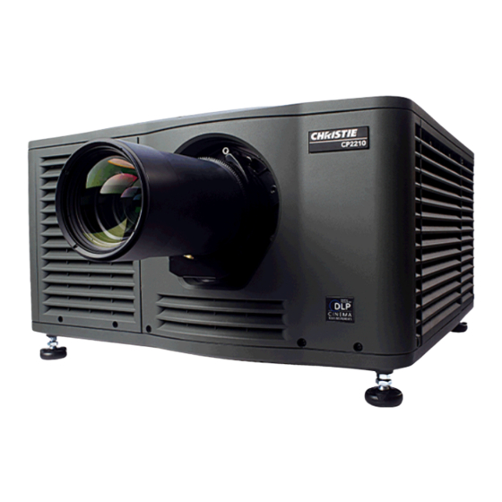
Christie CP2210 User Manual
Projection systems
Hide thumbs
Also See for CP2210:
- User manual (164 pages) ,
- Service manual (146 pages) ,
- Setup manual (58 pages)
Table of Contents
Advertisement
Quick Links
Advertisement
Table of Contents

Related Manuals for Christie CP2210


Summary of Contents for Christie CP2210
- Page 1 CP2210 U s e r M a n u a l 020-100410-08...
- Page 3 CP2210 U S E R M A N U A L 020-100410-08...
- Page 4 Performance specifications are based on information available at the time of printing. Christie makes no warranty of any kind with regard to this material, including, but not limited to, implied warranties of fitness for a particular purpose. Christie will not be liable for errors contained herein or for incidental or consequential damages in connection with the performance or use of this material.
-
Page 7: Table Of Contents
4.8 Fold Mirror Adjustment.......................4-5 4.9 Color Calibration .........................4-5 4.10 Electronic Screen Masking ......................4-6 4.11 Work with 3D ..........................4-6 4.11.1 Display Requirements......................4-6 4.11.2 Hardware Setup........................4-6 4.11.3 Install a 3D Server with an YCxCz Interface ..............4-7 CP2210 User Manual 020-100410-08 Rev. 1 (05-2014) - Page 8 6: Cinema Projector Menus 6.1 The Touch Panel Controller (TPC)....................6-1 6.2 Main Screen ..........................6-2 6.3 Open the On Screen Keyboard ....................6-4 6.4 User Access and Rights .......................6-5 6.5 Status Window ..........................6-7 6.6 Alarm Window ..........................6-11 CP2210 User Manual 020-100410-08 Rev. 1 (05-2014)
- Page 9 6.16.4 System Access Window.....................6-52 6.16.5 IMB Marriage Window .....................6-53 6.17 About Window .........................6-54 6.18 Help Window..........................6-55 7: Maintenance 7.1 Inspect Ventilation........................7-1 7.2 Fill the Coolant Reservoir......................7-1 7.3 Inspect the Optional Exhaust Duct (P/N: 119-103105-xx) ............7-1 CP2210 User Manual 020-100410-08 Rev. 1 (05-2014)
- Page 10 A.1.1 Panel Resolution and Refresh Rate ..................A-1 A.1.2 Achievable Brightness (Measured at Screen Center)............A-1 A.1.3 Achievable Contrast Ratio ....................A-1 A.1.4 Color and Gray Scale ......................A-1 A.1.5 White Point..........................A-1 A.1.6 Gamma ..........................A-1 A.2 Source Signal Compatibility .......................A-2 CP2210 User Manual 020-100410-08 Rev. 1 (05-2014)
- Page 11 A.7 Physical Specifications .......................A-8 A.8 Regulatory...........................A-8 A.8.1 Safety ..........................A-8 A.8.2 Electro-Magnetic Compatibility ..................A-8 A.9 Environment ..........................A-9 A.9.1 Operating Environment.......................A-9 A.9.2 Non-Operating Environment ....................A-9 A.10 Accessories ..........................A-9 A.10.1 Standard (sold with product)....................A-9 A.10.2 Accessories (sold separately) ...................A-9 CP2210 User Manual 020-100410-08 Rev. 1 (05-2014)
-
Page 13: Labels And Marking
1 Introduction This manual is intended for professionally trained operators of Christie high-brightness projection systems. These operators are qualified to replace the lamp and air filter, but should not attempt to install or service the cinema projector. Only accredited Christie technicians who are knowledgeable about the hazards associated with high-voltage, ultraviolet exposure, and the high temperatures generated by the cinema projector lamp are authorized to assemble, install, and service the cinema projector. -
Page 14: Power Warnings
Ensure that you are using a line cord, socket and power plug that meets the appropriate local rating standards. Use only an AC power cord recommended by Christie. DO NOT attempt operation if the AC supply and cord are not within the specified voltage and power range. -
Page 15: Contact Your Dealer
Section 1: Introduction Contact Your Dealer If you encounter a problem with your Christie cinema projector, contact your dealer. To assist with the servicing of your cinema projector, enter the information in the tables and keep this information with your records. -
Page 17: 2: Installation And Setup
Projection Lens A variety of lenses can be used with this cinema projector. See the Appendix A: Specifications for a list of available lenses. Security Locks Prevent unauthorized access to cinema projector components CP2210 User Manual 020-100410-08 Rev. 1 (05-2014) - Page 18 PIB Faceplate Connections • 10Base-T/100Base-TX Ethernet: Connects the cinema projector to a network. • GPIO: Connects the cinema projector to external input and output devices, such as the Christie ACT. See Connecting Devices to the GPIO Port for GPIO pinouts.
-
Page 19: Position The Cinema Projector
NOTE: Keep the cinema projector lens as parallel to the screen as possible, even if significantly above the screen center. When a particularly short throw distance combines with a very wide screen, you may have to CP2210 User Manual 020-100410-08 Rev. 1 (05-2014) -
Page 20: Adjust Tilt And Level The Cinema Projector
To adjust the vertical or horizontal position of the cinema projector, extend or retract the adjustable feet on the bottom of the cinema projector by rotating them. Once the required adjustment is made, tighten the lock nut. CP2210 User Manual 020-100410-08 Rev. 1 (05-2014) -
Page 21: Install The Touch Panel Controller
450 CFM* when the cinema projector is operating at less than or equal to 25°C ambient and less than 3,000 feet, when measured at the cinema projector exhaust opening. CP2210 User Manual 020-100410-08 Rev. 1 (05-2014) -
Page 22: Determine The Cinema Projector Exhaust Cfm Value
4. Adjust the location of the anamorphic lens so that the image does not shift left or right with the anamorphic lens in and out. CP2210 User Manual 020-100410-08 Rev. 1 (05-2014) -
Page 23: Install The Optional Wide Converter Lens
2.10 Install the Lamp DANGER DANGER This procedure should only be performed by a Christie accredited technician. High-pressure lamp may explode if improperly handled. Always wear approved protective safety clothing whenever the lamp door is open or when handling the lamp. -
Page 24: Connect Power
In countries such as Norway, a dedicated, protected earth wire must be installed on the cinema projector before it can be connected to an IT power distribution system. You must use a 20A branch circuit breaker for Input A. The dedicated earth wire can only be installed by a Christie accredited service WARNING technician or an electrician. - Page 25 Open the integrator rod access door and remove the second service panel screw. c. Push the clips on the top of the service panel down and out to remove the service panel. CP2210 User Manual 020-100410-08 Rev. 1 (05-2014)
- Page 26 7. Connect the protected earth wire to the cinema projector: a. Loosen the threaded bolt on the ground lug (A). b. Remove 15 mm of the insulated covering from the end of the protected earth wire. 2-10 CP2210 User Manual 020-100410-08 Rev. 1 (05-2014)
- Page 27 Tighten the threaded bolt to 50 in-lb. 8. Replace the side skin. Make sure the protected earth wire is not caught between the skin and cinema projector structure. 9. Replace the service door. 10. Replace the top lid. CP2210 User Manual 2-11 020-100410-08 Rev. 1 (05-2014)
-
Page 29: 3: Connect Devices To The Cinema Projector
Cinema servers are connected to one of the ports on the cinema projector Intelligence Board (PIB) located on the left (operator’s) side of the cinema projector. (Figure 3-1) Figure 3-1 Connecting Cinema Sources CP2210 User Manual 020-100410-08 Rev. 1 (05-2014) -
Page 30: Connect A Communications Device
Power On mode, lamp is ON +5V Standby Current limited 5VDC supply Lamp OFF cinema projector at full power, lamp is +5V Standby Current limited 5VDC supply Douser Closed Close douser Douser Open Douser open CP2210 User Manual 020-100410-08 Rev. 1 (05-2014) -
Page 31: Connecting Devices To The Gpio Port
To configure the pins on the connector, tap Menu > Administrator Setup > GPIO Setup. Pin 1 Pin 37 GPIO Connector Figure 3-3 Admin: GPIO Setup Window and GPIO Port Location on cinema projector CP2210 User Manual 020-100410-08 Rev. 1 (05-2014) - Page 32 = 50 mA Max. Current Forward Voltage Drop ~ 1.1 V (@ 5 mA) +5 VDC (External Supply) To Center Pin of BNC To Shielding of BNC IR Emitter Figure 3-4 GPIO Circuit Diagram CP2210 User Manual 020-100410-08 Rev. 1 (05-2014)
-
Page 33: Connecting Devices To The 3D Connector
GPIO requirements and restrictions. (24VDC max, 50mA max) CONN_SYNC- SYNC from cinema projector. From cinema projector GPO emitter. Compatible with current cinema projector GPIO requirements and restrictions. (24DC max, 50mA max) Not connected CP2210 User Manual 020-100410-08 Rev. 1 (05-2014) -
Page 35: 4: Adjusting The Image
2. Tap Do Auto. Calibrate Screen Brightness (fL) 1. On the Touch Pad Controller, tap Menu > Administrator Setup > Foot Lamberts Calibration. 2. Complete t he Foot Lamberts Calibration wizard. Figure 4-1 Footlamberts Calibration Wizard CP2210 User Manual 020-100410-08 Rev. 1 (05-2014) -
Page 36: Basic Image Alignment
This procedure ensures that the image reflected from the digital micromirror device (DMD) is parallel and centered with the lens and screen. This procedure must be completed before you complete a boresight adjustment. 1. Verify the CP2210 is properly positioned relative to the screen. See 2.2 Position the Cinema Projector. -
Page 37: Adjust Horizontal Boresight
(i.e. factory setup of absolute lens distance to the prism). It is critical that you count each turn of the cap screws to ensure accurate adjustment. Horizontal boresight should only be adjusted if a large horizontal tilt to the screen is required CP2210 User Manual 020-100410-08 Rev. 1 (05-2014) - Page 38 (i.e. factory setup of absolute lens distance to the prism). It is critical that each turn of the cap screws is tracked to ensure adjustments are accurate., on page 4-2. CP2210 User Manual 020-100410-08 Rev. 1 (05-2014)
-
Page 39: Adjust Dmd Convergence
Normally, the three colors should overlap precisely to form pure white lines throughout the image and one or more poorly converged individual colors may appear adjacent to some or all of the lines. Contact your Christie accredited service technician to correct DMD convergence issues. -
Page 40: Electronic Screen Masking
This section provides information and procedures for setting up and managing 3D presentations. 4.11.1 Display Requirements To display 3D images with the CP2210 cinema projector, you require these items: • Two HD-SDI cinema signals (left and right) connected to the cinema projector’s SMPTE ports HD-SDI A and HD-SDI B. -
Page 41: Install A 3D Server With An Ycxcz Interface
2. Select 3D Flat 1998x1080 in the Channel Name list. 3. Tap Config 1 in the left pane and edit these settings: a. Select 292-Dual in the Input list. b. Select YCrCb 4:2:2 10 bits x2 in the Data Format list. CP2210 User Manual 020-100410-08 Rev. 1 (05-2014) -
Page 42: Edit The 3D Scope 2048 X 858 Channel
5. Tap 3D Control in the left pane and edit these settings: a. Select Line Interleave in the 3D Sync Input Mode list. b. Select 6:2 in the Frame Rate N:M list. c. Select Left (L1R1 L2R2) in the L/R Display Sequence list. CP2210 User Manual 020-100410-08 Rev. 1 (05-2014) -
Page 43: Display 3D Diagnostic Test Patterns
100% black field with 100% red (TL), 100% black field with 100% white (TL), white (TR), blue (BR), green (BL) boxes red (TR), green (BR), blue (BL) boxes Figure 4-6 RGB-12 bit -3D Dynamic Range Test Pattern CP2210 User Manual 020-100410-08 Rev. 1 (05-2014) - Page 44 100% black field FRAME 4 - 100% white field box in FRAME 3 - 100% white field box in 100% black field 100% black field Figure 4-7 RGB-12bit-3D Four Quadrant Test Pattern 4-10 CP2210 User Manual 020-100410-08 Rev. 1 (05-2014)
- Page 45 Figure 4-8 RGB-12bit-3D Half Descending Test Pattern Green field with white “L” and last lines Magenta field with last lines 75% white, 25% white, 75% black 25% black Figure 4-9 RGB-12bit-3D L-Test Pattern CP2210 User Manual 4-11 020-100410-08 Rev. 1 (05-2014)
-
Page 46: Verify 3D Cinema Content
No 3D Effect 1. Tap Menu > Channel Setup. 2. Select a 3D channel in the Channel Name list. 3. Tap 3D Control in the left pane. 4. Verify Enable 3D is selected. 4-12 CP2210 User Manual 020-100410-08 Rev. 1 (05-2014) -
Page 47: Present Movies
4.12.1 Connect Sources Connect a digital media storage device or cinema server to one of the 292A or 292B input ports. For a list of standard single-link SMPTE 292M Formats, see Appendix A: Specifications. CP2210 User Manual 4-13 020-100410-08 Rev. 1 (05-2014) -
Page 48: Use An Anamorphic Lens
The optional Wide Converter Lens (WCL) magnifies a flat image with a format of 1.85:1 to a scope image with a 2.39:1 format, while maintaining the full resolution of the source material. Figure 4-11 Using Wide Converter Lens to Achieve “Scope” with No Resizing 4-14 CP2210 User Manual 020-100410-08 Rev. 1 (05-2014) -
Page 49: Masking
Each channel file contains the optimum processing and display settings for the source. You select channels on the Main Touch Pad Controller (TPC) screen. If the channel you need is not listed on the Main panel, click All. CP2210 User Manual 4-15... -
Page 51: Turn The Cinema Projector On
5 Operation This section describes how to operate the CP2210 cinema projector. Turn the Cinema Projector On DO NOT attempt to turn the cinema projector on if the AC supply is not WARNING within the specified voltage range. 1. Ensure the circuit breaker for the cinema projector is ON. -
Page 52: Cinema Projector Power States
New critical alarm New critical alarm or warning has NOT been acknowledged by operator. or warning Solid Red Existing critical Critical alarm or warning exists, but has been acknowledged by operator. alarm or warning CP2210 User Manual 020-100410-08 Rev. 1 (05-2014) -
Page 53: Work With The Lamp
6. Tap the directional arrows to adjust the values displayed in the X and Y fields. The brightness reading in front of the lens should be maximized. 7. Repeat Steps 5-6, but take your readings at the screen instead of at the lens. CP2210 User Manual 020-100410-08 Rev. 1 (05-2014) -
Page 54: View Lamp Information
Min Lamp Power Max Lamp Power CXL-14M 1.4 kW 1000W (70)% 1575W (110%) CXL-16M 1.6 kW 1000W (62)% 1760W (110%) CDXL-18SD 1.8 kW 1000W (56%) 1980W (110%) CDXL-20SD 2 kW 1000W (50%) 2100W (105%) CP2210 User Manual 020-100410-08 Rev. 1 (05-2014) -
Page 55: Work With Lenses
3. Tap the directional arrows to adjust the values displayed in the X, Y, and Zoom fields. These values over- write the ILS settings. 5.6.4 Maintain Lens Position Regardless of Selected Channel 1. On the Main screen of the TPC, tap Lens Adjust. 2. Clear the Enable Automatic ILS check box. CP2210 User Manual 020-100410-08 Rev. 1 (05-2014) -
Page 56: Reset The Ils
You must calibrate the ILS must when you install a new lens. 1. On the Main screen of the TPC, tap Lens Adjust. 2. Tap Full Calibration. If Enable Automatic ILS is not selected, the lens returns to the stored settings. CP2210 User Manual 020-100410-08 Rev. 1 (05-2014) -
Page 57: 6: Cinema Projector Menus
100 feet. If the TPC fails or is disconnected, press the emergency start button that is recessed on the faceplate. This starts the cinema projector, turns the lamp on, and opens the douser. CP2210 User Manual 020-100410-08 Rev. 1 (05-2014) -
Page 58: Main Screen
Status window and resolve issues. For information about the Status window, Status Error Message 6.5 Status Window 2: Channels Buttons Displays custom cinema projector settings. 3: All Channels Button Displays 64 saved channels. CP2210 User Manual 020-100410-08 Rev. 1 (05-2014) - Page 59 Power, Run, and Marriage. A green LED indicates the system is functioning correctly. A red LED indicates a critical error that you must correct. Click the status LED to open the Status window and resolve issues. CP2210 User Manual 020-100410-08 Rev. 1 (05-2014)
-
Page 60: Open The On Screen Keyboard
Open the On Screen Keyboard Tap the Launch Dialog button to open the On Screen Keyboard. The Onscreen Keypad is only available when you need to enter numerical values. Figure 6-2 On Screen Keypad CP2210 User Manual 020-100410-08 Rev. 1 (05-2014) -
Page 61: User Access And Rights
- Lamp Change Wizard - Lamp History - LampLOC™ Setup - ILS File Setup - Lens Setup - Source File Setup - Screen File Setup - MCGD File Setup - TCGD File Setup CP2210 User Manual 020-100410-08 Rev. 1 (05-2014) - Page 62 - Network Devices Setup - GPIO Setup - Foot Lamberts Calibration - User Accounts - Upgrade Service Setup - File Management (except Marriage) (except - LD/IMB Marriage Marriage) - System Access About Help CP2210 User Manual 020-100410-08 Rev. 1 (05-2014)
-
Page 63: Status Window
To adjust the width of a column in the left pane, click and drag the column border. When you close the Status window, the column widths return to their default size. Figure 6-3 Status Window CP2210 User Manual 020-100410-08 Rev. 1 (05-2014) - Page 64 Flash Self Test LVDS Self Test LampLOC™ Main Code - CRC LampLOC™ State LampLOC™ X Sensor LampLOC™ Y Sensor LampLOC™ Z Sensor EVB Main Code - CRC EVB State LVPS AC OK LVPS DC OK CP2210 User Manual 020-100410-08 Rev. 1 (05-2014)
- Page 65 Power Good 24V STBY ICP Free Disk Space (KB) ICP Total Disk Space (KB) Versions Package Version TPC Software TPC OS EVB Main EVB Boot EVB Hardware IMCB Lamp Boot IMCB Lamp Main IMCB Lamp Hardware CP2210 User Manual 020-100410-08 Rev. 1 (05-2014)
- Page 66 Security Lid Tamper The Certificates on the LD have been Zeroized ICP-LD Communication Error Serials TI ICP cinema projector Backplane LampLOC™ Board ILS Board Primary Lens Auxiliary Lens Lamp Ballast 6-10 CP2210 User Manual 020-100410-08 Rev. 1 (05-2014)
-
Page 67: Alarm Window
To acknowledge an alarm and remove it from the Alarms window, click Acknowledge. To view all alarms, tap Menu > Status > All Alarms in the left pane. Figure 6-4 Alarm Window CP2210 User Manual 6-11 020-100410-08 Rev. 1 (05-2014) -
Page 68: Interrogator Window
Download to USB to copy the log and batch files to a USB drive. NOTE: Log files are compressed into a .7z or 7-zip file format. A tool for opening these archives can be downloaded from http://www.7-zip.org. Figure 6-5 Diagnostics: Interrogator Window 6-12 CP2210 User Manual 020-100410-08 Rev. 1 (05-2014) -
Page 69: Smpte Errors Window
The total/recent count of 292-B errors. Clear Errors Resets SMPTE Error Counts to 0. This is used for testing to see if the error returns. SMPTE Error History A history of SMPTE errors. CP2210 User Manual 6-13 020-100410-08 Rev. 1 (05-2014) -
Page 70: System Logs Window
The start date for the log file reporting period. The end date for the log file reporting period. Type The type of log file to retrieve. These are the available options: System Event Maintenance Operational Security Engineering 6-14 CP2210 User Manual 020-100410-08 Rev. 1 (05-2014) -
Page 71: Server Test Window
To verify the subtitle and metadata files for a movie, play the movie and then open the Server Test window. The Meta File URI and Subtitling URI fields are populated with the .xml file names if they exist. Figure 6-8 Diagnostics: Server Test CP2210 User Manual 6-15 020-100410-08 Rev. 1 (05-2014) -
Page 72: Dlp Management Window
Resets the ICP board. Do not select this option when a movie is playing. DLP Self Test Runs ICP and LD self tests of the DLP hardware and returns the results on-screen. 6-16 CP2210 User Manual 020-100410-08 Rev. 1 (05-2014) -
Page 73: Network Devices
Network Devices Setup window. See 6.15.8 Network Devices Setup Window, on page 6-42 Figure 6-10 Accessing Christie ACT via the Network Devices Window To interact with the device tap in the top right corner of the window. To alter the zoom of the device tap , in the top right corner of the window. -
Page 74: Channel Setup Windows
The currently displayed file does not exist on the system and needs to be defined in the Advanced Setup window. 9: Defaults Applies the factory default settings of the current channel or all channels. 6-18 CP2210 User Manual 020-100410-08 Rev. 1 (05-2014) -
Page 75: Config 1 Window
The ILS configuration associated with the channel. Click Launch Dialog to edit the ILS file settings. Any changes made to the ILS File settings are applied to all channels that use this ILS file. 10: Auxiliary Lens Indicates if the channel uses an anamorphic lens. CP2210 User Manual 6-19 020-100410-08 Rev. 1 (05-2014) -
Page 76: Config 2 Window
* NOTE: Components marked with an asterisk (*) are part of pre-defined PCFs (cinema projector Configuration Files) that controls image processing for a given source. When you select Use PCF, these options are not available. 6-20 CP2210 User Manual 020-100410-08 Rev. 1 (05-2014) -
Page 77: Control Window
For more information, see 4.11 Work with Figure 6-15 Channel Setup: 3D Control Window Table 6.10 3D Control Window Control Description 1: Enable 3D Enables 3D. 2: 3D Test Displays 3D test patterns. Patterns CP2210 User Manual 6-21 020-100410-08 Rev. 1 (05-2014) - Page 78 = start early. Tap Launch Dialog to enter the output delay value. 10: Phase Delay The degree of reference between the left and right sync output. Values between -180 and 180 are accepted. Tap Launch Dialog to enter the phase delay value. 6-22 CP2210 User Manual 020-100410-08 Rev. 1 (05-2014)
- Page 79 (-) or later (+). Too much offset can cause “bleed-through” where each eye sees some data that is intended for the other, or causes color cropping since some DMD sequences may be clipped. CP2210 User Manual 6-23...
-
Page 80: Advanced Setup Windows
TCGD File Setup windows. Changes are applied to all channels that use this file. 2: Save As Saves the configuration file with a new name. 3: Save Saves the configuration file. 4: Revert Cancels unsaved screen settings and reapplies the saved settings. 6-24 CP2210 User Manual 020-100410-08 Rev. 1 (05-2014) -
Page 81: Lamp Power / Liteloc™ Setup Window
5: Text Region The current light sensor reading in arbitrary units-of -measure and does not represent actual lumens or fL. 6: Light Bar The current light intensity and LiteLOC ™ target . CP2210 User Manual 6-25 020-100410-08 Rev. 1 (05-2014) -
Page 82: Lamp History Window
The reason for changing the lamp. Add Lamp Add Lamp Window, on page 6-27 Tap Add Lamp to open the Add Lamp window. See Acknowledge Acknowledge the lamp has been rotated. Lamp Rotation 6-26 CP2210 User Manual 020-100410-08 Rev. 1 (05-2014) -
Page 83: Add Lamp Window
The number of hours the lamp operates before it is replaced. For information about lamp expiry hours for available lamps, see 5.5.8 Lamp Expiry Hours. Hours Used The number of hours the lamp has operated. CP2210 User Manual 6-27 020-100410-08 Rev. 1 (05-2014) -
Page 84: Lamploc™ Setup Window
Press and hold a button to increase or decrease the lamp position by multiple Buttons increments. You cannot move the lamp beyond the pre-defined limits for the cinema projector. For CP2210, X/Y = +/-250; Z = +/-175. Value Shows the current light sensor reading in arbitrary units-of -measure and does not represent actual lumens or fL. -
Page 85: Ils File Setup Window
Adjusts the offset. Quick Reset Resets the lens to the mechanical center before moving back to the original position. MALM Reset Resets the position of the MALM to the mechanical reference point. CP2210 User Manual 6-29 020-100410-08 Rev. 1 (05-2014) -
Page 86: Lens Setup Window
Perform a full ILS calibration and returns the lens to the manual position. Calibration MALM Installed Indicates a MALM is installed on the cinema projector. MALM Reset Resets the position of the MALM to the mechanical reference point. 6-30 CP2210 User Manual 020-100410-08 Rev. 1 (05-2014) -
Page 87: Source File Setup Window
The allowable X range is -4096 to 4096 pixels and Y range of -2160 to 2160 pixels. 3: Aspect Ratio The aspect ratio for the incoming signal. The allowable range is 0 to 7.99.. CP2210 User Manual 6-31 020-100410-08 Rev. 1 (05-2014) -
Page 88: Screen File Setup Window
7.99. Enter 1 if you are not using an anamorphic lens. Presentation The size and location of the image. By default, the cinema projector uses a 4096 x 2160 panel. Cropping Hides unwanted image data. 6-32 CP2210 User Manual 020-100410-08 Rev. 1 (05-2014) -
Page 89: Mcgd File Setup Window
5. Enter the values in the X and Y fields of the MCGD File Setup window. 6. Repeat Steps 3 - 5 for each color. 7. Select Off and then tap Save. CP2210 User Manual 6-33 020-100410-08 Rev. 1 (05-2014) -
Page 90: Tcgd File Setup Window
The brightness or intensity of each color when compared with a full white, ranging from 0 (0%) to 1 (100%). 4: Display Test Shows a test pattern when the color changes. Pattern 5: White Enables the White Tolerance grid and x and y text boxes. Tolerance 6-34 CP2210 User Manual 020-100410-08 Rev. 1 (05-2014) -
Page 91: Administrator Setup Windows
An alphabetical list of the 64 available channels. 2: Selected The 9 buttons that display on the Main panel of the TPC. Channel Buttons 3: Trash Can Deletes a channel from the Selected Channel Buttons area. CP2210 User Manual 6-35 020-100410-08 Rev. 1 (05-2014) -
Page 92: Preferred Test Pattern Setup Window
4: Test Displays the selected test pattern. 5: Full Screen Displays the test pattern full screen, 2048 x 1080. 6: Trash Can Used to delete a test pattern from the User Selected region. 6-36 CP2210 User Manual 020-100410-08 Rev. 1 (05-2014) -
Page 93: Preferences Window
Over Temperature, Fan Failure, Opens an alarm window when a pre-defined event occurs. Lamp Rotation, Lamp Expiry, LD Log Warning Brightness Adjusts the brightness of the touch screen display. Calibrate Screen Opens the Calibrate window. CP2210 User Manual 6-37 020-100410-08 Rev. 1 (05-2014) -
Page 94: Content Devices Configuration
Figure 6-31 Content Devices Configuration Window Table 6.25 Content Devices Configuration Control Description LD Installed Indicates a Link Decrypter (LD) is installed. IMB Installed Indicates an Image Media Block (IMB) is installed. 6-38 CP2210 User Manual 020-100410-08 Rev. 1 (05-2014) -
Page 95: Time Setup Window
Displays time in a 24-hour format. Adjust for Daylight Savings Automatically adjusts the time for daylight savings. Time Time Offset Increases or decreases the cinema projector time. Apply Time Applies time adjustment settings. Adjustment CP2210 User Manual 6-39 020-100410-08 Rev. 1 (05-2014) -
Page 96: Scheduler Window
Administrator or Service permissions. Tap Menu > Administrator Setup > Scheduler. Figure 6-33 Administrator Setup: Scheduler Window Table 6.27 Administrator Setup: Scheduler Setup Window Control Description Enable Scheduler Enables or disables the scheduler. Delete All Deletes all scheduled events. 6-40 CP2210 User Manual 020-100410-08 Rev. 1 (05-2014) -
Page 97: Communications Configuration Window
SNMP settings, and remote access settings. To open the Communications Configuration window you need Administrator or Service permissions. Tap Menu > Administrator Setup > Communications Configuration. Figure 6-34 Communications Configuration Window CP2210 User Manual 6-41 020-100410-08 Rev. 1 (05-2014) -
Page 98: Network Devices Setup Window
Grants access to Ethernet connections. 6.15.8 Network Devices Setup Window Use the Network Devices window to view the web interface of external peripherals such as Christie ACT and the Integrated Media Block (IMB). Tap Menu > Administrator Setup > Network Devices Setup. -
Page 99: Gpio Setup Window
The rising edge for the signal. Falling Edge The falling edge for the signal. Trigger The trigger that is sent when the function is activated. Output The output that triggers the GPIO signal. CP2210 User Manual 6-43 020-100410-08 Rev. 1 (05-2014) -
Page 100: Foot Lamberts Calibration Window
Foot Lamberts Calibration during a show, the show stops. To run the Foot Lamberts Calibration wizard you need Administrator or Service permissions. Tap Menu > Administrator Setup > Foot Lamberts Calibration. Figure 6-37 Foot Lamberts Calibration Start Window 6-44 CP2210 User Manual 020-100410-08 Rev. 1 (05-2014) -
Page 101: User Accounts Window
User Name and A list of all users and their permissions. Permission Adds a username, password and permission level for a new user. Edit Edit user passwords and permissions. Delete Deletes a user account. CP2210 User Manual 6-45 020-100410-08 Rev. 1 (05-2014) - Page 102 Section 6: Projector Menus Figure 6-39 Add a New User Window 6-46 CP2210 User Manual 020-100410-08 Rev. 1 (05-2014)
-
Page 103: Upgrade Window
A visual representation of the amount of used disk space on the cinema projector. Free Space The amount of available free space on the cinema projector. Upload Uploads a file. Remove Deletes an upgrade file. Next Opens the Extraction window. CP2210 User Manual 6-47 020-100410-08 Rev. 1 (05-2014) -
Page 104: Service Setup Windows
Removes all configurations and upgrades all components. 6.16 Service Setup Windows To open the Service Setup window you need Service permissions. Use the Service Setup windows to manage backup and restores of cinema projector data. 6-48 CP2210 User Manual 020-100410-08 Rev. 1 (05-2014) -
Page 105: System Access Window
Table 6.33 System Access Window Control Description Task Manager Opens the Microsoft Windows Task Manager. Computer Management Opens the Computer Management window. Windows Explorer Opens Windows Explorer. Network Connections Opens the Network Connections window. CP2210 User Manual 6-49 020-100410-08 Rev. 1 (05-2014) -
Page 106: File Management Window
1. Tap Browse. 2. Navigate to the location of the backup file. 3. Select the backup file and click Open. 4. In the Select restore type list, select a file type. 5. Tap Restore. 6-50 CP2210 User Manual 020-100410-08 Rev. 1 (05-2014) -
Page 107: Ld Marriage Window
Use the Marriage wizard to activate marriage on the cinema projector. Marriage engages the Direct Couple Interlock (DCI) and allows you to display secure content. You need Marriage permission to use the Marriage wizard and only Christie accredited technicians are authorized to activate cinema projector marriage. Figure 6-44 Marriage Start Window... -
Page 108: System Access Window
Table 6.35 Window Control Description Task Manager Opens the Microsoft Windows Task Manager. Computer Management Opens the Computer Management window. Windows Explorer Opens Windows Explorer. Network Connections Opens the Network Connections window. 6-52 CP2210 User Manual 020-100410-08 Rev. 1 (05-2014) -
Page 109: Imb Marriage Window
Use the Marriage wizard to activate Image Media Block (IMB) marriage on the cinema projector. IMB marriage engages the Direct Couple Interlock (DCI) and allows you to display secure content. You need Marriage permission to use the Marriage wizard and only Christie accredited technicians are authorized to activate IMB marriage. -
Page 110: About Window
Digital Light Processing (DLP) version, the lens and lamp type. If the cinema projector has been upgraded, a U appears at the end of the model number. Figure 6-47 About Window 6-54 CP2210 User Manual 020-100410-08 Rev. 1 (05-2014) -
Page 111: Help Window
Section 6: Projector Menus 6.18 Help Window Use the Help window to view information about the Touch Panel Controller (TPC) windows. Figure 6-48 Help Window CP2210 User Manual 6-55 020-100410-08 Rev. 1 (05-2014) -
Page 113: Inspect Ventilation
Top up the coolant with the Christie approved coolant JEFFCOOL E105. Use the refill bottle (with the nozzle) provided in the Liquid Coolant Fill Service Kit (P/N: 003-001837-xx). When refilling, use caution not to spill or let any of the coolant drip on or near the electronics. -
Page 114: Inspect The Lamp
1. Brush most of the dust off with a camelhair brush or use a dust-free blower. 2. Wrap a lens tissue around a swab and soak it in lens cleaning solution. The tissue should be damp but not dripping. CP2210 User Manual 020-100410-08 Rev. 1 (05-2014) -
Page 115: Clean The Lamp Reflector
Wash the radiator filter with water and a mild detergent or clean it with compressed air. d. Ensure the air filter is completely dry and insert it with the air flow indicator facing toward the cinema projector. 4. Reinstall the service door and the top lid. CP2210 User Manual 020-100410-08 Rev. 1 (05-2014) -
Page 116: Inspect And Clean Lamp Blower
HAZARD. Wear authorized protective clothing whenever the lamp door is open and when handling the lamp. Never twist or bend the quartz lamp body. Use the correct wattage lamp supplied by Christie. 3) Ensure those within the vicinity of the cinema projector are also wearing protective safety clothing. 4) Never attempt to remove the lamp when it is hot. - Page 117 9. Close the internal lamp door and manually turn the 2 thumbscrews to lock it in place. 10. Close the rear access door. NOTE: Return the hex key to its holder before closing the rear access door. CP2210 User Manual 020-100410-08 Rev. 1 (05-2014)
-
Page 118: Rotate The Lamp
Never twist or bend the quartz lamp body. Use the correct wattage lamp supplied by Christie. 3) Ensure those within the vicinity of the cinema projector are also wearing protective safety clothing. 4) Never attempt to remove the lamp when it is hot. -
Page 119: Replace The Air Filter
Section 7: Maintenance 7.10 Replace the Air Filter Use only high efficiency Christie approved filters. Never operate the cinema projector without the filter installed. Always discard used air filters. You should check the condition of the light engine air filter monthly. Replace the light engine air filter when you replace the lamp module or sooner if you are operating the cinema projector in a dusty or dirty environment. -
Page 120: Replace The Lens
Once the lens makes contact with the magnetic plates it will be seated correctly and the connector for motorized zoom and focus will be properly connected (Figure 7-7). 9. Secure the lens clamp by pushing it down to the closed position. CP2210 User Manual 020-100410-08 Rev. 1 (05-2014) - Page 121 10. For added stability, secure the cap screws provided on the lens mount. If you have installed a large zoom lens, one or more of the screws may be inaccessible - simply tighten those that are accessible. NOTE: Recommended for heaviest lenses, such as 0.8:1 and 1.3-1.75:1. Figure 7-7 Install Lens CP2210 User Manual 020-100410-08 Rev. 1 (05-2014)
-
Page 123: Cinema Projector Does Not Turn On
• Listen for a clicking noise that indicates the ballast is attempting to strike the lamp. If you do not hear a clicking noise, there might be a problem a problem with the ballast. Contact a Christie accredited service technician to resolve the issue. -
Page 124: Lamp Suddenly Turns Off
Increase the lamp power. Lamps which are near end of service may not operate reliably at a lower power setting. • Fold mirror misalignment. Contact your Christie accredited service technician to resolve the issue. • Integrator rod misalignment. Contact your Christie accredited service technician to resolve the issue. -
Page 125: Cannot Establish Communication With Cinema Projector
Setup. Tap Config 1 in the left pane and verify the correct value is selected in the PCF list. Tap Config 2 in the left pane and verify the correct value is selected in the Color Space field. CP2210 User Manual 020-100410-08 Rev. 1 (05-2014) -
Page 126: Display Is Not Rectangular
8.19 The Display is Jittery or Unstable • Verify that the input device is connected properly. If the input device is not connected properly, the cinema projector repeatedly attempts to display an image. CP2210 User Manual 020-100410-08 Rev. 1 (05-2014) -
Page 127: The Display Is Faint
• Use an anamorphic lens for HDTV and anamorphic DVD input sources that have been re-sized and verti- cally stretched. 8.23 Inconsistent Picture Quality • Verify the quality of the signal from the input source. • Verify the H and V frequencies of the input source are correct. CP2210 User Manual 020-100410-08 Rev. 1 (05-2014) -
Page 129: Display
Appendix A: Specifications This section provides detailed Christie CP 2210 specifications. Due to continuing research, specifications are subject to change without notice. A.1 Display A.1.1 Panel Resolution and Refresh Rate Pixel format (H x V square pixels) 2048 x 1080 Processing path 23.97 - 120Hz... -
Page 130: Source Signal Compatibility
1920 x 1080 23.98 / 24 Progressive (sF) 23.98 / 24 SMPTE RP 211 1920 x 1080 Progressive (sF) SMPTE RP 211 1920 x 1080 29.97 / 30 Progressive (sF) 29.97 / 30 CP2210 User Manual 020-100410-08 Rev. 1 (05-2014) - Page 131 Also supported is 4:2:2 YCbCr progressive input with 10 or 12 bits per component and a pixel format of 1920 x 1080 at 47.96 or 48 fps. 3) For 3D content, the supported format is 4:2:2 YCbCr 10 bit per eye. CP2210 User Manual 020-100410-08 Rev. 1 (05-2014)
-
Page 132: Non-Cinema Dvi Inputs (For Alternate Content
59.94 / 60 Hz 1440 x 576 50 Hz 1920 x 1080 50 Hz 1920 x 1080 23.98 / 24 Hz 1920 x 1080 29.97 / 30 Hz 720 x 480 119.88 / 120 Hz CP2210 User Manual 020-100410-08 Rev. 1 (05-2014) -
Page 133: Control Signal Compatibility
16 - 8 inputs, 8 outputs including 1 health signal output Type of Connection Opto-isolated Input Current 5mA nominal, 50mA maximum Output Current 50mA maximum Input forward voltage drop 1.1V nom., 1.4V max. (@5mA) CP2210 User Manual 020-100410-08 Rev. 1 (05-2014) -
Page 134: Simple Contact Closure Interface (Scci) Port
195 mm x 148 mm x 44.4 mm ® Integrated Operating System Microsoft Windows Communication Interface with cinema projector 10/100Base-T Ethernet Power Requirement 1.02 A maximum at 24VDC ± 10% Interface Connector 12-pin Circular connector (push-pull) CP2210 User Manual 020-100410-08 Rev. 1 (05-2014) -
Page 135: Tpc-650H
NOTE: The ballast is power regulated to a maximum of 180A. Therefore the maximum power specification for a given lamp may not be achievable until the lamp has aged, since lamp voltage increases with hours of use. Average Life: CXL-14M 3000 hours CP2210 User Manual 020-100410-08 Rev. 1 (05-2014) -
Page 136: Physical Specifications
• EU Directive (2002/95/EC) on the restriction of the uses of certain hazardous substances (RoHS) in electri- cal and electronic equipment and the applicable official amendments) • EU Directive (2002/96/EC) on waste and electrical and electronic equipment (WEEE) and the applicable official amendment(s) CP2210 User Manual 020-100410-08 Rev. 1 (05-2014) -
Page 137: Environment
• 1.75-2.4 DLPCine Zoom Lens (108-321107-01) • 1.9-3.0 DLPCine Zoom Lens (108-328104-01) • 2.4-3.9 DLPCine Zoom Lens (108-322108-01) • 3.9-6.5 DLPCine Zoom Lens (108-323109-01) Auxiliary Lenses • 1.25x Anamorphic Lens (38-809054-01) • 1.26x Wide Converter Lens (108-281101-01) CP2210 User Manual 020-100410-08 Rev. 1 (05-2014) - Page 138 • Replacement Lamps • CDXL-14M (003-003066-01) • CDXL-18SD (003-002742-01) • CDXL-20SD (003-001976-01) • Replacement Air Filter (003-002311-01) • Liquid Cooling Kit (003-001837-03) • Extractor Adaptor Kit (119-103105-01) • DLP Cinema Firmware Installation Program ® A-10 CP2210 User Manual 020-100410-08 Rev. 1 (05-2014)
- Page 139 *000-101833-07* ASSY TECH DOCS CP2210...
- Page 140 Corporate offi ces Worldwide offi ces USA – Cypress United Kingdom Eastern Europe Singapore Japan ph: 714-236-8610 ph: +44 118 977 8000 ph: +36 (0) 1 47 48 100 ph: +65 6877-8737 ph: 81-3-3599-7481 Canada – Kitchener France Middle East Beijing South Korea ph: 519-744-8005...