Brocade Communications Systems ICX 7750 Installation Manual
Switch hardware
Hide thumbs
Also See for ICX 7750:
- Faq (4 pages) ,
- Configuration manual (593 pages) ,
- Software update (128 pages)

Related Manuals for Brocade Communications Systems ICX 7750


Summary of Contents for Brocade Communications Systems ICX 7750
- Page 1 HARDWARE INSTALLATION GUIDE Brocade ICX 7750 Switch Hardware Installation Guide Supporting FastIron Software Release 8.0.40a 53-1003900-02 8 April 2016...
- Page 2 The authors and Brocade Communications Systems, Inc. assume no liability or responsibility to any person or entity with respect to the accuracy of this document or any loss, cost, liability, or damages arising from the information contained herein or the computer programs that accompany it.
-
Page 3: Table Of Contents
............. 6 Brocade ICX 7750 slot and Ethernet port numbering . - Page 4 ..................49 System specifications Brocade ICX 7750 Switch Hardware Installation Guide 53-1003900-02...
- Page 5 BSMI statement (Taiwan) Brocade ICX 7750 Cautions and Danger Notices ....................59 Cautions .
- Page 6 Brocade ICX 7750 Switch Hardware Installation Guide 53-1003900-02...
-
Page 7: Preface
In Fibre Channel products, a fixed value provided as input to a command option is printed in plain text, for example, --show WWN. Syntax components displayed within square brackets are optional. Default responses to system prompts are enclosed in square brackets. Brocade ICX 7750 Switch Hardware Installation Guide 53-1003900-02... -
Page 8: Notes, Cautions, And Warnings
White papers, online demonstrations, and data sheets are available through the Brocade website. Contacting Brocade Technical Support As a Brocade customer, you can contact Brocade Technical Support 24x7 online, by telephone, or by e-mail. Brocade OEM customers contact their OEM/Solutions provider. viii Brocade ICX 7750 Switch Hardware Installation Guide 53-1003900-02... -
Page 9: Brocade Customers
By sending your feedback to documentation@brocade.com. Provide the publication title, part number, and as much detail as possible, including the topic heading and page number if applicable, as well as your suggestions for improvement. Brocade ICX 7750 Switch Hardware Installation Guide 53-1003900-02... - Page 10 Document feedback Brocade ICX 7750 Switch Hardware Installation Guide 53-1003900-02...
-
Page 11: About This Document
What’s new in this document ................1 Supported hardware and software This document is specific to the Brocade ICX 7750 running FastIron release 8.0.40a. What’s new in this document The following table describes information added to this guide for FastIron software releases 8.0.40a. - Page 12 What’s new in this document Brocade ICX 7750 Switch Hardware Installation Guide 53-1003900-02...
-
Page 13: Brocade Icx 7750 Overview
(must be ordered separately). Advanced software. No optics. Brocade ICX 7750 customizable models The Brocade ICX 7750 base systems do not ship with power supplies or fans. Fans and power supplies are ordered separately to allow for building the system that meets your network needs. -
Page 14: Views Of The Brocade Icx 7750 Switch
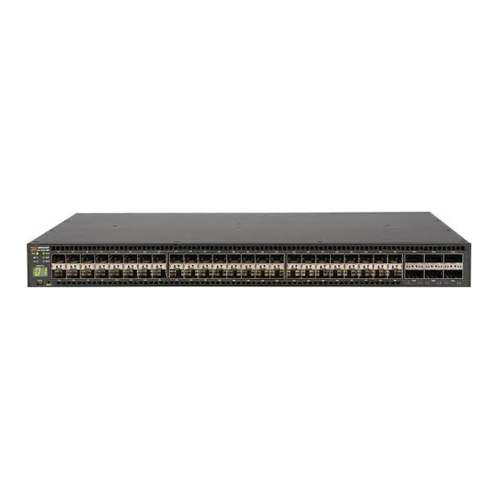
Brocade ICX 7750 6-port QSFP+ expansion/stacking module. Views of the Brocade ICX 7750 switch Figure 1 shows the front view of the Brocade ICX 7750-26Q switch. FIGURE 1 Front view of the Brocade ICX 7750-26Q QSFP+ ports XL1/1 - XL1/20 and XL2/1 - XL2/6... - Page 15 System LEDs SFP+ port LEDs Stack unit ID display QSFP+ port LEDs Figure 3 shows the front view of the Brocade ICX 7750-48C switch. FIGURE 3 Front view of the Brocade ICX 7750-48C 10GBase-T RJ-45 ports 1/1 - 1/48 Console port...
-
Page 16: Brocade Icx 7750 Slot And Ethernet Port Numbering
• Slot 1 and Slot 2 are located on the front of the Brocade ICX 7750-26Q device. Slot 1 contains 10/40 GbE QSFP+ ports XL1/1 through XL1/20; odd port numbers on the top row with port XL1/1 on the left and port XL1/20 on the right. Slot 2 contains 10/40 GbE QSFP+ ports XL2/1 through XL2/6;... -
Page 17: Supported Expansion Module
• Slot 1 and Slot 2 are located on the front of the Brocade ICX 7750-48F device. Slot 1 contains 1/10 GbE SFP+ ports 1/1 through 1/48, with odd port numbers on the top row and port 1/1 on the left. Slot 2 contains 10/40 GbE QSFP+ ports XL2/1, XL2/3, and XL2/5 on the top row (left to right), and ports XL2/2, XL2/4, and XL2/6 on the bottom row (left to right). -
Page 18: Supported Transceivers And Cables
For a list of supported transceivers and cables, refer to the Brocade Optics Family Data Sheet. QSFP+ 40GBase-LR4 support The Brocade ICX 7750 supports 40GBASE-LR4 QSFP+ LC optics (up to 10 km over SMF) in the port ranges shown in Table... -
Page 19: Breakout Cables
1/3/1 through 1/3/6 QSFP+ to SFP+ adapter support The Brocade ICX 7750 supports a third-party QSFP+ to SFP+ adapter for cost-effective connections between 40 GbE QSFP+ ports and 10 GbE hardware using standard SFP+ optical cabling rather than breakout cables. - Page 20 Supported transceivers and cables Brocade ICX 7750 Switch Hardware Installation Guide 53-1003900-02...
-
Page 21: Installing The Brocade Icx 7750
Procedures in this manual are intended for qualified service personnel. Unpacking the device The Brocade ICX 7750 ships with all of the items listed in the following list. Verify the contents of your shipping container. If any items are missing, contact the place of purchase. -
Page 22: Electrical Considerations
• Because the Brocade ICX 7750 can be ordered with fans that move air either front to back or back to front, be sure to orient your switch with the airflow pattern of any other devices in the rack. All equipment in the rack should force air in the same direction to avoid intake of exhaust air. -
Page 23: Recommendations For Cable Management
Ensure that the physical environment that will host the device has the proper “Installation and safety considerations” on page 11 cabling and ventilation. If customizing a Brocade ICX 7750 baseline chassis: “Installing and replacing a power supply unit” page 20 Install at least one power supply unit. -
Page 24: Installation Precautions
Use a separate branch circuit for each AC power cord, which provides redundancy in case one of the circuits fails. DANGER To avoid high voltage shock, do not open the device while the power is on. Brocade ICX 7750 Switch Hardware Installation Guide 53-1003900-02... -
Page 25: Dc-Dc Power Source Cautions
12.) • Mechanical loading: Do not place any equipment on top of a rack-mounted unit. • Circuit overloading: Be sure that the supply circuit to the rack assembly is not overloaded. Brocade ICX 7750 Switch Hardware Installation Guide 53-1003900-02... -
Page 26: 2-Post Rack Mount Installation
NOTE Use the following procedure when installing the Brocade ICX 7750 in a 2-post Telco rack only. If an ICX 7750 device is to be installed into a standard 4-post rack, make sure that the correct rack mount kit has been purchased. For 4-post racks, follow the procedures in “4-post rack mount installation”... -
Page 27: 4-Post Rack Mount Installation
Kits for 4-post rack mounting are not included in the shipping carton and must be ordered separately. NOTE Use the following procedure when installing the Brocade ICX 7750 in a 4-post rack cabinet. For 2-post cabinets, follow the procedures in “2-post rack mount installation”... - Page 28 NOTE Use the hardware supplied in the 4-post mounting kit for mid-mounting the Brocade ICX 7750 in a 4-post rack. When front-flush or reverse mounting in a 4-post rack, use the L-shaped brackets from the 2-post rack mounting kit instead of those in the 4-post kit to prevent the side cooling vents from being blocked.
-
Page 29: Grounding The System
Grounding the system The rear panel of the Brocade ICX 7750 includes a single-screw grounding terminal. The surface area around this terminal is not painted to provide a good electrical connection. Before connecting power to the device, the grounding terminal must be connected to ground to ensure proper operation and to meet electromagnetic interference (EMI) and safety requirements. -
Page 30: Power Supplies
CAUTION For Brocade ICX 7750 devices, be sure that the airflow direction of the power supply unit matches that of installed fan trays. The power supplies and fan trays are clearly labeled with either a green arrow with an “E”, or an orange arrow with an “I.”... -
Page 31: Installing A Dc Power Supply
When you are sure the power supply has properly engaged the connector, tighten the retainer screws to secure the power supply in the slot. When the Brocade ICX 7750 is powered on, the LEDs on the power supply rear panel should light up green to confirm that the power supply is correctly installed and supplying power. - Page 32 AC and DC power supplies cannot be installed and used in the same device. Mismatched power supplies in the same device cause continual reboot on power up. Use the following steps to install a DC power supply in the Brocade ICX 7750. Remove the previously installed power supply from the appropriate slot by removing the chassis attachment screws located in the upper right and lower left of the power supply unit using a Phillips screwdriver.
-
Page 33: Attaching A Pc Or Terminal
When you are sure the power supply has properly engaged the connector, tighten the chassis attachment screws to secure the power supply in the slot. When the Brocade ICX 7750 is powered on, the power LED on the front of the device should turn green to confirm that the power supply is correctly installed and supplying power. Refer to “Brocade ICX 7750 front-panel LEDs”... -
Page 34: Connecting To The Management Port
The Gigabit Ethernet management port (RJ-45) on the Brocade ICX 7750 rear panel provides an out-of-band network connection to the device. After you assign an IP address, you can access the Brocade ICX 7750 from anywhere in the attached network using Telnet, a web browser, or other network management tools, such as Brocade Network Advisor. -
Page 35: Connecting Network Devices
“Data port specifications (Ethernet)” on page 52. Connecting a network device to a copper port For copper connections to another Brocade device or any other devices, use straight-through or crossover UTP cabling. Brocade ICX 7750 Switch Hardware Installation Guide 53-1003900-02... -
Page 36: Connecting A Network Device To A Fiber Port
Connecting breakout cables to 40 GbE ports A 40 GbE breakout cable can only be used on standalone Brocade ICX 7750 devices to break out certain 40 GbE QSFP+ ports into four 10 GbE sub-ports. (Refer to “Breakout cables”... -
Page 37: Stacking Brocade Icx 7750 Switches
Any previous configuration must be removed from a 40 GbE port before it can be broken out into sub-ports. Refer to the Brocade FastIron Management Configuration Guide for more information. NOTE Stacking cannot be enabled on Brocade ICX 7750 devices that have a breakout configuration on any 40 GbE ports, and vice versa. Stacking Brocade ICX 7750 switches Brocade ICX 7750 devices support chassis-class high availability stacking with hitless failover on six full-duplex 40 Gbps stacking ports. -
Page 38: Stacking Configuration Requirements
Unused stacking ports can be used as data ports. For example, you can elect to use only one default port as a stacking port and use the other default port as a data port. Furthermore, when a Brocade ICX 7750-6Q stacking module is not configured for stacking, its ports can be used as data ports. -
Page 39: Stacking Cables
10 kilometers for ICX 7750-26Q device only Stack size The Brocade ICX 7750 supports up to 12 units in a stack. You can mix any number of Brocade ICX 7750-26Q, Brocade ICX 7750-48F, or Brocade ICX 7750-48C devices together in a stack. - Page 40 FIGURE 23 Rear panel ring stacking topology Figure 24 shows a supported front panel ring stacking topology. FIGURE 24 Front panel ring stacking topology Brocade ICX 7750 Switch Hardware Installation Guide 53-1003900-02...
- Page 41 Stacking Brocade ICX 7750 switches Figure 25 shows a supported rear panel ring trunk-stack topology. FIGURE 25 Rear panel ring trunk-stack topology NOTE For more information about stacking, refer to the Brocade FastIron Stacking Configuration Guide. Brocade ICX 7750 Switch Hardware Installation Guide 53-1003900-02...
- Page 42 Stacking Brocade ICX 7750 switches Brocade ICX 7750 Switch Hardware Installation Guide 53-1003900-02...
-
Page 43: Brocade Icx 7750 Operation
LEDs do not indicate a healthy state after all boot processes and diagnostic tests are complete. Brocade ICX 7750 front-panel LEDs The Brocade ICX 7750-26Q has the following LEDs on the front panel: • Two power supply unit (PSU) bicolor status LEDs (green and amber) labeled PSU1 and PSU2 •... - Page 44 4x10 GbE breakout mode Figure 27 shows the LEDs on the Brocade ICX 7750-48C front panel. The up-arrow port status LEDs for the 1/10 GbE ports correspond to the upper, odd-numbered ports; the down-arrow port status LEDs correspond to the lower, even-numbered ports.
- Page 45 PSU2 corresponds to the left power supply slot, as viewed from the rear) The Brocade ICX 7750-48F has the following LEDs on the front panel: • Two power supply unit (PSU) bicolor status LEDs (green and amber) labeled PSU1 and PSU2 •...
-
Page 46: Brocade Icx 7750 Rear-Panel Leds
PSU2 corresponds to the left power supply slot, as viewed from the rear) Brocade ICX 7750 rear-panel LEDs The Brocade ICX 7750 has the following LEDs on the rear panel: • Two Management port status LEDs •... -
Page 47: Led Patterns
LEDs Upper slot 10 GbE mode lanes 2, 3, and 4 Expansion module power LED link/activity LEDs LED patterns The following tables describe the Brocade ICX 7750 LED patterns. TABLE 8 PSU1 and PSU2 LEDs LED state Status of hardware... - Page 48 No action required. received. Steady amber Link is up in 1 GbE mode. No action required. Blinking amber There is 1 GbE traffic and packets are being transmitted or No action required. received. Brocade ICX 7750 Switch Hardware Installation Guide 53-1003900-02...
- Page 49 Module is on and booting up. No action required. TABLE 21 Fan tray LED LED state Status of hardware Recommended action Off (no light) Fan tray is not powered on. No action required. Brocade ICX 7750 Switch Hardware Installation Guide 53-1003900-02...
-
Page 50: Diagnostic Tests And Monitoring
System diagnostic testing runs at link speeds 10 Gbps and 40 Gbps (QSFP+ ports) depending on the speed of the link being tested and the type of port. Brocade ICX 7750 Switch Hardware Installation Guide 53-1003900-02... -
Page 51: Managing The Brocade Icx 7750
Replacing a copper or fiber-optic module You can remove an SFP+, or QSFP+ transceiver from a slot and replace it with a new one while the Brocade ICX 7750 is powered on and running. -
Page 52: Cabling A Fiber-Optic Module
Laser radiation. Do not view directly with optical instruments. Class 1M laser products. NOTE When 10 GbE fiber-optic ports on the Brocade ICX 7750 are disabled, the laser light remains on even though the port link is down. To remove a copper or fiber-optic module from a transceiver slot, do the following. -
Page 53: Fru Removal And Replacement Procedures
If a mismatched power source or fan tray is installed by mistake, a warning is sent to the console. The warning messages will be similar to the following: • For a fan mismatch: [WARNING, Brocade ICX 7750, MISMATCH in Fan Air Flow direction. Replace FRU with fan air flows in the same direction. •... -
Page 54: Replacing A Power Supply Unit
CAUTION For the Brocade ICX 7750 devices, be sure that the airflow direction of the power supply unit matches that of the installed fan tray. The power supplies and fan trays are clearly labeled with either a green arrow with an “E”, or an orange arrow with an “I.”... -
Page 55: Replacing Fan Trays
The power supply will immediately attempt to power up. Verify that the LED on the new power supply displays steady green while the Brocade ICX 7750 is operating. If the LED is not steady green, ensure that the power supply is securely installed and seated properly. Alternatively, check the PSU1 and PSU2 LEDs on the switch front panel (refer to “LED patterns”... -
Page 56: Determining The Need To Replace A Fan Tray
Enter the show chassis command in the command line interface to display fan status. Time and items required Replacing a fan tray in the Brocade ICX 7750 should take less than two minutes to complete. You need the following items to replace a fan tray in the Brocade ICX 7750: •... -
Page 57: Replacing An Expansion Module
Replacing an expansion module Replacing an expansion module The Brocade ICX 7750 includes a rear-panel slot for a 6-port QSFP+ 40 GbE expansion module. If not installed, the empty expansion module slot must be covered using the filler panel. CAUTION Disassembling any part of the expansion module voids the warranty and regulatory certifications. - Page 58 If you do not install a power supply in a slot, you must keep the slot panel in place. If you run the device with an uncovered slot, the system will overheat. Brocade ICX 7750 Switch Hardware Installation Guide 53-1003900-02...
-
Page 59: System Specifications
System architecture Nonblocking shared memory switch ICX 7750-26Q: 26 10/40 GbE QSFP+ ports ICX 7750-48F: 48 1/10 GbE SFP+ ports and six 10/40 GbE QSFP+ ports ICX 7750-48C: 48 1/10 GbE RJ-45 ports and six 10/40 GbE QSFP+ ports System processors System processor 1.5 GHz Freescale P2041... -
Page 60: Leds
Environmental requirements Condition Operational Non-operational Ambient temperature ICX 7750-26Q: -5º to 50ºC (23º to 122ºF) -40º to 60ºC (-40º to 140ºF) ICX 7750-48F: -5º to 50ºC (23º to 122ºF) ICX 7750-48C: -5º to 40ºC (23º to 104ºF) Relative humidity (non-condensing) ICX 7750-26Q and ICX 7750-48F: 10% to 90% at 60ºC (140ºF) -
Page 61: Power Supply Specifications (Per Psu)
Fan speed is at nominal. 867 BTU/hr 853 BTU/hr 853 BTU/h ICX 7750-48C 510 W 511 W 511 W 1 AC or DC Fan speed is at nominal. 1740 BTU/hr 1744 BTU/hr 1744 BTU/hr Brocade ICX 7750 Switch Hardware Installation Guide 53-1003900-02... -
Page 62: Power Consumption (Maximum Configuration)
10GBASE-T, 1/10 Gbps, capable of auto-negotiating link speed. Serial port specifications (pinout mini-USB) TABLE 33 Serial port specifications (pinout mini-USB) Signal Description Reserved Not used UART0_RX Data received by ICX UART0_TX Data transmitted by ICX Brocade ICX 7750 Switch Hardware Installation Guide 53-1003900-02... -
Page 63: Serial Port Specifications (Pinout Rj-45)
Main memory DDR3 8 GB Boot Flash NOR Flash 64 MB eUSB Drive 2 GB Regulatory compliance (EMC) • FCC Part 15, Subpart B (Class A) • EN 55022 (CE mark) (Class A) Brocade ICX 7750 Switch Hardware Installation Guide 53-1003900-02... -
Page 64: Regulatory Compliance (Safety)
• 30/2011/TT-BCT – Vietnam circular • SJ/T 11363-2006 Requirements for Concentration Limits for Certain Hazardous Substances in EIPs (China) • SJ/T 11364-2006 Marking for the Control of Pollution Caused by EIPs (China) Brocade ICX 7750 Switch Hardware Installation Guide 53-1003900-02... -
Page 65: Usa (Fcc Cfr 47 Part 15 Warning)
Maschinenlärminformations-Verordnung - 3. GPSGV, der höchste Schalldruckpegel beträgt 53.0 dB(A) gemäss EN ISO 7779. English translation of above statement Machine noise information regulation - 3. GPSGV, the highest sound pressure level value is 53.0 dB(A) in accordance with EN ISO 7779. Brocade ICX 7750 Switch Hardware Installation Guide 53-1003900-02... -
Page 66: Japan (Vcci)
Class A device (Broadcasting Communication Device for Office Use): This device obtained EMC registration for office use (Class A), and may be used in places other than home. Sellers and/or users need to take note of this. Brocade ICX 7750 Switch Hardware Installation Guide 53-1003900-02... -
Page 67: China
English translation of above statement This is a Class A product. In a domestic environment this product may cause radio interference, inwhich case the user may be required to take adequate measures. Brocade ICX 7750 Switch Hardware Installation Guide 53-1003900-02... -
Page 68: Bsmi Statement (Taiwan)
English translation of above statement Warning: This is a class A product. In a domestic environment this product may cause radio interference in which case the user may be required to take adequate measures. Brocade ICX 7750 Switch Hardware Installation Guide 53-1003900-02... -
Page 69: Brocade Icx 7750 Cautions And Danger Notices
CAUTION All devices with DC power supplies (Brocade ICX 7750 ) are intended for installation in restricted access areas only. A restricted access area is where access can be gained only by service personnel through the use of a special tool, lock and key, or other means of security, and is controlled by the authority responsible for the location. - Page 70 Never leave tools inside the chassis. VORSICHT Lassen Sie keine Werkzeuge im Chassis zurück. MISE EN GARDE Ne laissez jamais d'outils à l'intérieur du châssis. PRECAUCIÓN No deje nunca herramientas en el interior del chasis. Brocade ICX 7750 Switch Hardware Installation Guide 53-1003900-02...
- Page 71 CAUTION For the ICX 7750 devices, be sure that the airflow direction of the power supply unit matches that of the installed fan tray. The power supplies and fan trays are clearly labeled with either a green arrow with an "E", or an orange arrow with an "I."...
- Page 72 CAUTION For the DC input circuit to the system of a Brocade ICX 7750, make sure there is a UL-Listed 20 Amp circuit breaker, minimum 60 VDC, double pole, on the input lugs to the power supply. The input wiring for connection to the product should be Listed copper wire, 12 AWG, marked VW-1, and rated minimum 90°C.
-
Page 73: Danger Notices
Débranchez le cordon d'alimentation de toutes les sources d'alimentation pour couper complètement l'alimentation du dispositif. PELIGRO Para desconectar completamente la corriente del instrumento, desconecte el cordón de corriente de todas las fuentes de corriente. Brocade ICX 7750 Switch Hardware Installation Guide 53-1003900-02... - Page 74 Das eingeschaltete Gerät darf nicht geöffnet werden, da andernfalls das Risiko eines Stromschlags mit Hochspannung besteht. DANGER Afin d'éviter tout choc électrique, n'ouvrez pas l'appareil lorsqu'il est sous tension. PELIGRO Para evitar una descarga de alto voltaje, no abra el dispositivo mientras esté encendido. Brocade ICX 7750 Switch Hardware Installation Guide 53-1003900-02...
Need help?
Do you have a question about the ICX 7750 and is the answer not in the manual?
Questions and answers