Brocade Communications Systems ICX 7450 Hardware Installation Manual
Hide thumbs
Also See for ICX 7450:
- Hardware installation manual (94 pages) ,
- Deployment manual (83 pages) ,
- Configuration manual (593 pages)

Related Manuals for Brocade Communications Systems ICX 7450


Summary of Contents for Brocade Communications Systems ICX 7450
- Page 1 HARDWARE INSTALLATION GUIDE Brocade ICX 7450 Switch Hardware Installation Guide Supporting FastIron Software Release 8.0.40a 53-1003899-02 8 April 2016...
- Page 2 The authors and Brocade Communications Systems, Inc. assume no liability or responsibility to any person or entity with respect to the accuracy of this document or any loss, cost, liability, or damages arising from the information contained herein or the computer programs that accompany it.
-
Page 3: Table Of Contents
............. 7 Brocade ICX 7450 slot and Ethernet port numbering . - Page 4 ..........51 Installing or replacing an expansion module or service module Brocade ICX 7450 Switch Hardware Installation Guide 53-1003899-02...
- Page 5 BSMI statement (Taiwan) Brocade ICX 7450 Cautions and Danger Notices ....................67 Cautions .
- Page 6 Brocade ICX 7450 Switch Hardware Installation Guide 53-1003899-02...
-
Page 7: Preface
In Fibre Channel products, a fixed value provided as input to a command option is printed in plain text, for example, --show WWN. Syntax components displayed within square brackets are optional. Default responses to system prompts are enclosed in square brackets. Brocade ICX 7450 Switch Hardware Installation Guide 53-1003899-02... -
Page 8: Notes, Cautions, And Warnings
White papers, online demonstrations, and data sheets are available through the Brocade website. Contacting Brocade Technical Support As a Brocade customer, you can contact Brocade Technical Support 24x7 online, by telephone, or by e-mail. Brocade OEM customers contact their OEM/Solutions provider. viii Brocade ICX 7450 Switch Hardware Installation Guide 53-1003899-02... -
Page 9: Brocade Customers
By sending your feedback to documentation@brocade.com. Provide the publication title, part number, and as much detail as possible, including the topic heading and page number if applicable, as well as your suggestions for improvement. Brocade ICX 7450 Switch Hardware Installation Guide 53-1003899-02... - Page 10 Document feedback Brocade ICX 7450 Switch Hardware Installation Guide 53-1003899-02...
-
Page 11: About This Document
What’s new in this document ................1 Supported hardware and software This document is specific to the Brocade ICX 7450 running FastIron release 8.0.40a. What’s new in this document The following table describes information added to this guide for FastIron software releases 8.0.40a. - Page 12 What’s new in this document Brocade ICX 7450 Switch Hardware Installation Guide 53-1003899-02...
-
Page 13: Brocade Icx 7450 Overview
Brocade ICX 7450 customizable switches The Brocade ICX 7450 base systems do not ship with power supplies, fans, stacking modules, or media expansion modules. Fans, power supplies, and expansion modules are ordered separately to allow for building the system that meets your network needs. -
Page 14: Views Of The Brocade Icx 7450 Switch
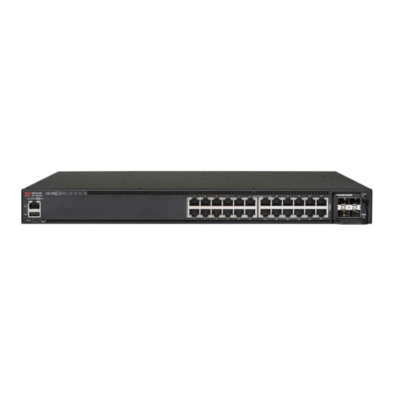
Brocade ICX 510 W DC PSU, power-supply-side intake (port-side exhaust) airflow ICX-FAN10-E Brocade ICX 7450 power-supply-side exhaust airflow fan (two fans required with two power supplies) ICX-FAN10-I Brocade ICX 7450 power-supply-side intake airflow fan (two fans required with two power supplies) - Page 15 Views of the Brocade ICX 7450 switch Figure 2 shows the front view of the Brocade ICX 7450-24P switch. NOTE PoE/PoE+ power is available to ports 1-24. High PoE/PoH is limited to ports 1-8. FIGURE 2 Front view of the Brocade ICX 7450-24P...
- Page 16 Views of the Brocade ICX 7450 switch Figure 4 shows the front view of the Brocade ICX 7450-48 switch. FIGURE 4 Front view of the Brocade ICX 7450-48 System LEDs Mini-USB console port Media/Stacking module LEDs Reset button Stack unit ID display...
-
Page 17: Brocade Icx 7450 Slot And Ethernet Port Numbering
Brocade ICX 7450 slot and Ethernet port numbering Figure 6 shows the front view of the Brocade ICX 7450-48F switch. FIGURE 6 Front view of the Brocade ICX 7450-48F System LEDs Mini-USB console port Media/Stacking module LEDs Reset button Stack unit ID display... - Page 18 • Slot 1 and Slot 2 are located on the front of the Brocade ICX 7450-24 and ICX 7450-24P devices. Slot 1 contains 1 GbE RJ-45 ports 1/1/1 through 1/1/24, with odd port numbers on the top row and port 1/1/1 on the left. Slot 2 contains 1/10 GbE SFP+ ports 1/2/1 and 1/2/3 on the top row (left to right), and ports 1/2/2 and 1/2/4 on the bottom row (left to right).
-
Page 19: Supported Expansion Modules
• Slot 1 and Slot 2 are located on the front of the Brocade ICX 7450-48F device. Slot 1 contains 1 GbE SFP ports 1/1/1 through 1/1/48, with odd port numbers on the top row and port 1/1/1 on the left. Slot 2 contains 1/10 GbE SFP+ ports 1/2/1 and 1/2/3 on the top row (left to right), and ports 1/2/2 and 1/2/4 on the bottom row (left to right). - Page 20 ICX7400-4X10GC 4X10G 4X1G 4X10G 4X1G 4X10G 4X1G ICX7400-1X40GQ 4X10G 4X10G 4X10G TABLE 4 Brocade ICX 7450-48, 48P and 48F expansion slots and supported media modules Module Slot 2 Slot 3 Slot 4 ICX7400-4X1GF 4X1G 4X10M/100M 4X1G 4X100M 4X1G 4X100M ICX7400-4X10GF...
-
Page 21: Supported Transceivers And Cables
QSFP+ 40GBase-SR-BD support The Brocade ICX 7450 supports 40GBASE-SR-BD bi-directional (BiDi) QSFP+ transceivers with duplex LC optics. The 40 GbE BiDi optics support two 20 GbE channels over duplex fiber cable, with the transmit and receive of each channel operating at two wavelengths on a single fiber. - Page 22 Supported transceivers and cables Brocade ICX 7450 Switch Hardware Installation Guide 53-1003899-02...
-
Page 23: Installing The Brocade Icx 7450
Procedures in this manual are intended for qualified service personnel. Unpacking the device The Brocade ICX 7450 ships with all of the items listed in the following list. Verify the contents of your shipping container. If any items are missing, contact the place of purchase. -
Page 24: Installation And Safety Considerations
• Because the Brocade ICX 7450 can be ordered with fans that move air either front to back or back to front, be sure to orient your switch with the airflow pattern of any other devices in the rack. All equipment in the rack should force air in the same direction to avoid intake of exhaust air. -
Page 25: Cabinet Considerations
Ensure that the physical environment that will host the device has the proper “Installation and safety considerations” on page 14 cabling and ventilation. If customizing a Brocade ICX 7450 baseline chassis: “Installing and replacing a power supply unit” on page 27 Install at least one power supply unit. -
Page 26: Installation Precautions
Risk of explosion if battery is replaced by an incorrect type. Dispose of used batteries according to the manufacturer’s instructions. Lifting precautions CAUTION Make sure the rack or cabinet housing the device is adequately secured to prevent it from becoming unstable or falling over. Brocade ICX 7450 Switch Hardware Installation Guide 53-1003899-02... -
Page 27: Power Precautions
The input wiring for connection to the product should be copper wire, 12 AWG, marked VW-1, and rated minimum 90°C. Installing the device on a desktop Complete the following steps to install the Brocade ICX 7450 on a desktop or other flat surface. Brocade ICX 7450 Switch Hardware Installation Guide 53-1003899-02... -
Page 28: Installing The Device In A Rack Or Cabinet
Grounding: Rack-mounted equipment should be properly grounded. Particular attention should be given to supply connections other than direct connections to the mains electricity supply. 2-post rack mount installation The Brocade ICX 7450 can be installed in a 2-post rack in various mounting positions, as shown in Figure Brocade ICX 7450 Switch Hardware Installation Guide... - Page 29 Front mid-mount 2-post rack, side view NOTE Use the following procedure when installing the Brocade ICX 7450 in a 2-post rack. For 4-post racks, follow the procedures in “4-post rack mount installation” on page 20. Use the following steps to mount the Brocade ICX 7450 in a 2-post rack.
-
Page 30: 4-Post Rack Mount Installation
Installing the device in a rack or cabinet FIGURE 16 Attaching the mounting brackets for a Brocade ICX 7450 Position the device in the cabinet, providing temporary support under the switch until the rail kit is secured to the cabinet. - Page 31 Installing the device in a rack or cabinet NOTE Use the following procedure when installing the Brocade ICX 7450 in a 4-post rack cabinet. For 2-post cabinets, follow the procedures in “2-post rack mount installation” on page 18. Use the following steps to mount the Brocade ICX 7450 in a 4-post rack.
-
Page 32: Connecting Devices In A Stack
Connecting devices in a stack The Brocade ICX 7450 can operate as a standalone device or as a member of a stack. A stack is a group of devices—Brocade stackable units and their connected stacking links—that are connected so that the stack is managed as a single entity. -
Page 33: Stacking Configuration Requirements
Stacking cables Use QSFP+ direct attached copper stacking cables or QSFP+ optics with fiber cables to connect the Brocade ICX 7450 devices in a stack. The copper cable lengths for 40 GbE ports are 0.5 meter, 1 meter, 3 meters, or 5 meters. - Page 34 FIGURE 23 Front panel linear stacking topology Figure 24 shows a supported front panel ring stacking topology. FIGURE 24 Front panel ring stacking topology NOTE For more information about stacking, refer to the Brocade FastIron Stacking Configuration Guide. Brocade ICX 7450 Switch Hardware Installation Guide 53-1003899-02...
-
Page 35: Grounding The System
Grounding the system The rear panel of the Brocade ICX 7450 includes a single-screw grounding terminal. The surface area around this terminal is not painted to provide a good electrical connection. Before connecting power to the device, the grounding terminal must be connected to ground to ensure proper operation and to meet electromagnetic interference (EMI) and safety requirements. -
Page 36: Power Supplies
If the second power supply and second fan slot are unused, you must cover them with filler panels. NOTE Brocade recommends that the Brocade ICX 7450 switch operates with two power supplies and two fan trays installed. If a power supply or fan tray fails, it must be replaced as soon as possible. -
Page 37: Installing And Replacing A Power Supply Unit
Power supplies For example, a Brocade ICX 7450-24P has two power supplies installed. If you increase the maximum number of PoE ports that can be supported, and if the primary power supply fails, the redundant power supply cannot guarantee the device is protected by backup power. -
Page 38: Installing A Dc Power Supply
When you are sure the power supply has properly engaged the connector, tighten the retainer screws to secure the power supply in the slot. When the Brocade ICX 7450 is powered on, the LEDs on the power supply rear panel should light up green to confirm that the power supply is correctly installed and supplying power. -
Page 39: Attaching A Pc Or Terminal
When you are sure the power supply has properly engaged the connector, tighten the chassis attachment screws to secure the power supply in the slot. When the Brocade ICX 7450 is powered on, the power LED on the front of the device should turn green to confirm that the power supply is correctly installed and supplying power. Refer to “Brocade ICX 7450 front-panel LEDs”... -
Page 40: Connecting To The Management Port
The Gigabit Ethernet management port (RJ-45) on the Brocade ICX 7450 front panel provides an out-of-band network connection to the device. After you assign an IP address, you can access the Brocade ICX 7450 from anywhere in the attached network using Telnet, a web browser, or other network management tools, such as Brocade Network Advisor. -
Page 41: Connecting Network Devices
Media Dependent Interface Crossover (MDIX) detection. Automatic MDI or MDIX detection is enabled on all copper ports by default. For each port, you can disable automatic MDI or MDIX, designate the port as an MDI port, or designate the port as an MDIX port. Brocade ICX 7450 Switch Hardware Installation Guide 53-1003899-02... -
Page 42: Connecting A Network Device To A Fiber Port
33. NOTE To verify that a Brocade ICX 7450 can reach another device through the network, use the ping command at any level of the CLI. For more information, refer to the Brocade FastIron Management Configuration Guide. Cleaning the fiber-optic connectors To avoid problems with the connection between the fiber-optic transceiver (SFP, SFP+, or QSFP+) and the fiber cable connectors, Brocade strongly recommends cleaning both connectors each time you disconnect and reconnect them. -
Page 43: Brocade Icx 7450 Operation
GbE mode of operation Figure 30 shows the LEDs on the Brocade ICX 7450-24 front panel. The up-arrow port status LEDs for the 1 GbE ports correspond to the upper, odd-numbered ports; the down-arrow port status LEDs correspond to the lower, even-numbered ports. - Page 44 Module 3 and 4 are the right and left stacking modules on the rear panel, as viewed from the rear. The Brocade ICX 7450-24P has the following LEDs on the front panel: • Two management port status LEDs (green) for speed and link/activity •...
- Page 45 Brocade ICX 7450 front-panel LEDs Figure 31 shows the LEDs on the Brocade ICX 7450-24P front panel. The up-arrow port status LEDs for the 1 GbE ports correspond to the upper, odd-numbered ports; the down-arrow port status LEDs correspond to the lower, even-numbered ports.
- Page 46 Figure 32 shows the LEDs on the Brocade ICX 7450-32ZP front panel. The up-arrow port status LEDs for the 1 GbE and 2.5 GbE ports correspond to the upper, odd-numbered ports; the down-arrow port status LEDs correspond to the lower, even-numbered ports.
- Page 47 Figure 33 shows the LEDs on the Brocade ICX 7450-48 front panel. The up-arrow port status LEDs for the 1 GbE ports correspond to the upper, odd-numbered ports; the down-arrow port status LEDs correspond to the lower, even-numbered ports.
- Page 48 Figure 34 shows the LEDs on the Brocade ICX 7450-48P front panel. The up-arrow port status LEDs for the 1 GbE ports correspond to the upper, odd-numbered ports; the down-arrow port status LEDs correspond to the lower, even-numbered ports.
- Page 49 Figure 35 shows the LEDs on the Brocade ICX 7450-48F front panel. The up-arrow port status LEDs for the 10 GbE ports correspond to the upper, odd-numbered ports; the down-arrow port status LEDs correspond to the lower, even-numbered ports.
-
Page 50: Brocade Icx 7450 Rear-Panel Leds
Brocade ICX 7450 rear-panel LEDs Brocade ICX 7450 rear-panel LEDs The Brocade ICX 7450 has the following LEDs on the rear panel: • Expansion module power LED: One bicolor status LED (green and amber) • QSFP+ module LEDs: Four status LEDs (green) for the stacking port on the QSFP+ modules. Only the first LED is currently used, and indicates the status of the port in 40 GbE mode. - Page 51 Verify the system is on and has completed booting. Steady green Indicates stack unit identifier. (Unit numbers 11 and 12 are shown by No action required. using the 10+ LED in combination with the 1 or 2 LED.) Brocade ICX 7450 Switch Hardware Installation Guide 53-1003899-02...
- Page 52 No action required. Steady amber Link is up in 1 GbE mode. No action required. Blinking amber There is 1 GbE traffic and packets are being transmitted or received. No action required. Brocade ICX 7450 Switch Hardware Installation Guide 53-1003899-02...
-
Page 53: Diagnostic Tests And Monitoring
In offline diagnostics, you must turn the diagnostic flags on or off to execute diagnostic tests during the next bootup. The CLI commands for system diagnostic tests are dm diag and dm alt-diag. These diagnostic tests verify all available hardware components including: • I2C devices Brocade ICX 7450 Switch Hardware Installation Guide 53-1003899-02... - Page 54 System diagnostic testing runs at link speeds of 10 Gbps or 40 Gbps (for MOD2 QSFP+ data uplink ports) or 40 Gbps (for MOD3/MOD4 QSFP+ stacking ports) depending on the speed of the link being tested and the type of port. Brocade ICX 7450 Switch Hardware Installation Guide 53-1003899-02...
-
Page 55: Managing The Brocade Icx 7450
Replacing a fiber-optic transceiver You can remove an SFP, SFP+, or QSFP+ transceiver from a slot and replace it with a new one while the Brocade ICX 7450 is powered on and running. -
Page 56: Cabling A Fiber-Optic Transceiver
FRU removal and replacement procedures The field-replaceable units (FRUs) in the Brocade ICX 7450 can be removed and replaced by using a #1 Phillips screwdriver. The switches can continue operating during the FRU replacement if the conditions specified in these procedures are followed. This covers both the power supply unit (PSU) FRUs and fan FRUs. -
Page 57: Replacing A Power Supply Unit
CAUTION For the Brocade ICX 7450 devices, be sure that the airflow direction of the power supply unit matches that of the installed fan tray. The power supplies and fan trays are clearly labeled with either a green arrow with an “E,” or an orange arrow with an “I.”... -
Page 58: Determining The Need To Replace A Power Supply
Complete the following steps to replace a power supply in a Brocade ICX 7450. To leave the Brocade ICX 7450 in service while replacing a power supply, verify that the other power supply (the one not being replaced) has been powered on for at least four seconds and has a steady green status LED. -
Page 59: Replacing Fan Trays
CAUTION For the Brocade ICX 7450 devices, be sure that the airflow direction of the fan tray matches that of the installed power supply unit. The power supplies and fan trays are clearly labeled with either a green arrow with an “E,” or an orange arrow with an “I.”... -
Page 60: Installing Or Replacing The Fan Assembly
Replacing an expansion module or service module The Brocade ICX 7450 includes one front-panel slot and two rear-panel slots for media expansion or service modules, including a 4-port SFP 1 GbE module, a 4-port SFP+ 10 GbE module, a 4-port Copper 10 GbE module, or a 1-port QSFP+ 40 GbE module. The slots in... -
Page 61: Installing Or Replacing An Expansion Module Or Service Module
• A #1 Phillips screwdriver Installing or replacing an expansion module or service module Complete the following steps to install or replace an expansion module or service module in the Brocade ICX 7450. Power off the switch. CAUTION The expansion modules are not hot-swappable. - Page 62 Replacing an expansion module or service module Brocade ICX 7450 Switch Hardware Installation Guide 53-1003899-02...
-
Page 63: System Specifications
System architecture Non-blocking shared-memory switch ICX 7450-24: 24 1-GbE RJ-45 ports, four 10-GbE SFP+ uplink ports, two 40-GbE QSFP+ stacking ports, one power supply, and one fan unit ICX 7450-24P: 24 1-GbE RJ-45 ports (supporting PoE, PoE+, High PoE, PoH), four 10-GbE SFP+ uplink ports, two 40-GbE QSFP+ stacking ports, one power supply, and one fan unit ICX7450-32ZP: 24 1-GbE RJ-45 ports, 8 2.5-GbE RJ-45 ports (supporting PoE, PoE+, High PoE, PoH),... -
Page 64: Ethernet
Ethernet Ethernet These are standard modules for shipping bundles. For Brocade ICX 7450 non-bundled switches, expansion modules need to be ordered separately. System component Description Maximum ports supported 40 GbE QSFP+ ports 1 40 GbE QSFP+ stacking or uplink port... -
Page 65: Weight And Physical Dimensions
Nominal: 5-7 cfm, Maximum: 17-20 cfm. Heat dissipation NOTE: Refer to “Power consumption (typical configuration)” (+/- 5%) page 56 and “Power consumption (maximum configuration)” on page 57 for detailed information on heat dissipation. Brocade ICX 7450 Switch Hardware Installation Guide 53-1003899-02... -
Page 66: Power Supply Specifications (Per Psu)
299 BTU/hr 276 BTU/hr 1 x 510 W DC 100.1 W 99.2 W 85.3W 1 x 250 W AC 2 PSUs 342 BTU/hr 339 BTU/hr 291 BTU/hr 1 x 510 W DC Brocade ICX 7450 Switch Hardware Installation Guide 53-1003899-02... -
Page 67: Power Consumption (Maximum Configuration)
1 x 510 W DC 1402 W 1374 W 669.06 W 2 x 1000 W AC 2 PSUs required for PoE loading 4785 BTU/hr 4690 BTU/hr 2284 BTU/hr 2 x 510 W DC Brocade ICX 7450 Switch Hardware Installation Guide 53-1003899-02... -
Page 68: Power Consumption (Modules)
Typical = 4.68 W two power supplies are used) Maximum = 16.68 W ICX-FAN10-I Power-supply intake airflow fan (two fans required if two Typical = 4.68 W power supplies are used) Maximum = 16.68 W Brocade ICX 7450 Switch Hardware Installation Guide 53-1003899-02... -
Page 69: Data Port Specifications (Ethernet)
1000Base-LHA SFP optic SMF, 1000Base-LX SFP optic SMF, 1000Base-SX SFP optic MMF, 1000BASE-TX SFP Copper Serial port specifications (pinout - mini-USB) Signal Description Reserved Not used UART0_RX Debug port (data received by ICX) UART0_TX Console port (data transmitted by ICX) Brocade ICX 7450 Switch Hardware Installation Guide 53-1003899-02... -
Page 70: Serial Port Specifications (Pinout Rj-45)
Regulatory compliance (EMC) • FCC Part 15, Subpart B (Class A) • EN 55022 (CE mark) (Class A) • EN 55024 (CE mark) (Immunity) for Information Technology Equipment • ICES-003 (Canada) (Class A) Brocade ICX 7450 Switch Hardware Installation Guide 53-1003899-02... -
Page 71: Regulatory Compliance (Safety)
• 30/2011/TT-BCT – Vietnam circular • SJ/T 11363-2006 Requirements for Concentration Limits for Certain Hazardous Substances in EIPs (China) • SJ/T 11364-2006 Marking for the Control of Pollution Caused by EIPs (China) Brocade ICX 7450 Switch Hardware Installation Guide 53-1003899-02... - Page 72 Regulatory compliance (environmental) Brocade ICX 7450 Switch Hardware Installation Guide 53-1003899-02...
-
Page 73: Usa (Fcc Cfr 47 Part 15 Warning)
Maschinenlärminformations-Verordnung - 3. GPSGV, der höchste Schalldruckpegel beträgt 53.0 dB(A) gemäss EN ISO 7779. English translation of above statement Machine noise information regulation - 3. GPSGV, the highest sound pressure level value is 53.0 dB(A) in accordance with EN ISO 7779. Brocade ICX 7450 Switch Hardware Installation Guide 53-1003899-02... -
Page 74: Japan (Vcci)
Class A device (Broadcasting Communication Device for Office Use): This device obtained EMC registration for office use (Class A), and may be used in places other than home. Sellers and/or users need to take note of this. Brocade ICX 7450 Switch Hardware Installation Guide 53-1003899-02... -
Page 75: China
English translation of above statement This is a Class A product. In a domestic environment this product may cause radio interference, in which case the user may be required to take adequate measures. Brocade ICX 7450 Switch Hardware Installation Guide 53-1003899-02... -
Page 76: Bsmi Statement (Taiwan)
English translation of above statement Warning: This is a class A product. In a domestic environment this product may cause radio interference in which case the user may be required to take adequate measures. Brocade ICX 7450 Switch Hardware Installation Guide 53-1003899-02... -
Page 77: Brocade Icx 7450 Cautions And Danger Notices
CAUTION All devices with DC power supplies (Brocade ICX 7450) are intended for installation in restricted access areas only. A restricted access area is where access can be gained only by service personnel through the use of a special tool, lock and key, or other means of security, and is controlled by the authority responsible for the location. - Page 78 Never leave tools inside the chassis. VORSICHT Lassen Sie keine Werkzeuge im Chassis zurück. MISE EN GARDE Ne laissez jamais d'outils à l'intérieur du châssis. PRECAUCIÓN No deje nunca herramientas en el interior del chasis. Brocade ICX 7450 Switch Hardware Installation Guide 53-1003899-02...
- Page 79 CAUTION For the ICX 7450 devices, be sure that the airflow direction of the power supply unit matches that of the installed fan tray. The power supplies and fan trays are clearly labeled with either a green arrow with an “E,” or an orange arrow with an “I.”...
- Page 80 CAUTION For the DC input circuit to the system of a Brocade ICX 7450 make sure there is a 20 Amp circuit breaker, minimum 60 VDC, double pole, on the input lugs to the power supply. The input wiring for connection to the product should be Listed copper wire, 12 AWG, marked VW-1, and rated minimum 90°C.
-
Page 81: Danger Notices
Die Verfahren in diesem Handbuch sind nur für qualifiziertes Wartungspersonal gedacht. DANGER Les procédures décrites dans ce manuel doivent être effectuées par le personnel de service qualifié uniquement. PELIGRO Los procedimientos de este manual se han hecho para personal de servicio cualificado. Brocade ICX 7450 Switch Hardware Installation Guide 53-1003899-02... - Page 82 Remove both power cords before servicing. GEFAHR Trennen Sie beide Netzkabel, bevor Sie Wartungsarbeiten durchführen. DANGER Retirez les deux cordons d'alimentation avant toute maintenance. PELIGRO Desconecte ambos cables de alimentación antes de realizar reparaciones. Brocade ICX 7450 Switch Hardware Installation Guide 53-1003899-02...
- Page 83 Rayonnement de laser. Ne regardez pas directement avec les instruments optiques. Produits de laser de la classe 1M. PELIGRO Radiacion de Laser. No vea directamente con Instrumentos Opticos. Clase 1M de Productos de Laser. Brocade ICX 7450 Switch Hardware Installation Guide 53-1003899-02...
- Page 84 Danger notices Brocade ICX 7450 Switch Hardware Installation Guide 53-1003899-02...
Need help?
Do you have a question about the ICX 7450 and is the answer not in the manual?
Questions and answers