Table of Contents
Advertisement
Quick Links
M362000-01 Rev E
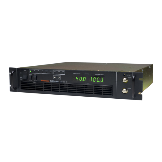
DLM-E 3kW & 4kW
Series Power
Supplies
Operation Manual
This manual covers models:
3kW
DLM5–350E
DLM8–350E
DLM16–185E
DLM32–95E
DLM40–75E
DLM60–50E
DLM80–37E
DLM150–20E
DLM300–10E
DLM600–5E
4kW
DLM5–450E
DLM8–450E
DLM16–250E
DLM22-180E
DLM32–125E
DLM40–100E
DLM60–66E
DLM80–50E
DLM150–26E
DLM300–13E
DLM600–6.6E
www.programmablepower.com
Advertisement
Table of Contents
Troubleshooting

Related Manuals for Ametek Sorensen DLM-E


Summary of Contents for Ametek Sorensen DLM-E
- Page 1 DLM-E 3kW & 4kW Series Power Supplies Operation Manual This manual covers models: DLM5–350E DLM5–450E DLM8–350E DLM8–450E DLM16–185E DLM16–250E DLM32–95E DLM22-180E DLM40–75E DLM32–125E DLM60–50E DLM40–100E DLM80–37E DLM60–66E DLM150–20E DLM80–50E DLM300–10E DLM150–26E DLM600–5E DLM300–13E DLM600–6.6E M362000-01 Rev E www.programmablepower.com...
-
Page 5: About Ametek
ABOUT AMETEK AMETEK Programmable Power, Inc., a Division of AMETEK, Inc., is a global leader in the design and manufacture of precision, programmable power supplies for R&D, test and measurement, process control, power bus simulation and power conditioning applications across diverse industrial segments. From bench top supplies to rack-mounted industrial power subsystems, AMETEK Programmable Power is the proud manufacturer of Elgar, Sorensen, California Instruments and Power Ten brand power supplies. - Page 6 This page intentionally left blank. viii M362000-01 Rev E...
-
Page 7: Important Safety Instructions
Neither AMETEK Programmable Power Inc., San Diego, California, USA, nor any of the subsidiary sales organizations can accept any responsibility for personnel, material or inconsequential injury, loss or damage that results from improper use of the equipment and accessories. - Page 8 This page intentionally left blank. M362000-01 Rev E...
-
Page 9: Warranty Terms
AMETEK will, at its expense, deliver the repaired or replaced Product or parts to the Buyer. Any warranty of AMETEK will not apply if the Buyer is in default under the Purchase Order Agreement or where the Product or any part thereof: is damaged by misuse, accident, negligence or failure to maintain the same as specified or required by AMETEK;... - Page 10 This page intentionally left blank. M362000-01 Rev E...
-
Page 11: About This Manual
ABOUT THIS MANUAL This manual has been written expressly for AMETEK’s Sorensen brand DLM–E 3kW and 4kW series of power supplies, which have been designed to meet the 1997 Low Voltage and Electromagnetic Compatibility Directive Requirements of the European Community, except DLM16-185E and DLM22-180E models. - Page 12 This page intentionally left blank. M362000-01 Rev E...
-
Page 13: Table Of Contents
CONTENTS About AMETEK ......................vii Important Safety Instructions ..................ix Warranty Terms ......................xi About This Manual ......................xiii SECTION 1 FEATURES AND SPECIFICATIONS ......... 1-1 Description ....................... 1-1 Operating Modes ..................... 1-1 Power Supply Features ................... 1-1 Specifications ....................1-3 1.4.1... - Page 14 Contents DLM-E 3kW & 4kW Series Power Supplies 2.4.1 Front Panel User Controls and Indicators .......... 2-4 2.4.2 Rear Panel ..................2-7 Location, Mounting, and Ventilation ..............2-8 2.5.1 Unit Dimensions ................. 2-8 2.5.2 Rack Mounting ................... 2-8 2.5.3 Ventilation ..................2-8 AC Input Power Connection ................
- Page 15 DLM-E 3kW & 4kW Series Power Supplies Contents 4.3.3 Programming Output Current Limit ..........4-10 4.3.4 Remote Programming Only the Output Voltage or Current Limit ..4-12 Using Over Voltage Protection (OVP) ............4-14 4.4.1 Front Panel OVP Operation ............. 4-14 4.4.2 Resetting the OVP Circuit ..............
- Page 16 Contents DLM-E 3kW & 4kW Series Power Supplies LIST OF TABLES Table 4–1. J3 Connector – Program, Control, and Monitor Description ......4-3 Table 4–2. Rear Panel S1 DIP Switch Functions and Settings ......... 4-4 Table 4–3. J12, J13 Connectors–Parallel Port Function and Pinout ....... 4-24 Table 5–1.
- Page 17 DLM-E 3kW & 4kW Series Power Supplies Contents LIST OF FIGURES Figure 2–1. EMI Suppression Filter .................. 2-2 Figure 2–2. DLM–E Controls, Connectors, and Indicators (5V–80V models) ....2-5 Figure 2-3. DLM–E Controls, Connectors, and Indicators (150V–600V models) ..... 2-6 Figure 2–4.
-
Page 19: Section 1 Features And Specifications
SECTION 1 FEATURES AND SPECIFICATIONS Description The DLM–E Series 3000 and 4000 watt power supplies are designed to provide highly stable, continuously variable output voltage and current for a broad range of development, system and burn–in applications. Model numbers for this series are designated by the DLM prefix, followed by the output voltage and current ratings. - Page 20 Features and Specifications DLM-E 3kW & 4kW Series Power Supplies • High input AC power factor, 0.98 typical, with single–phase input. • Front panel controls for Enable/Standby and Local/Remote modes of operation. • Simultaneous digital display of both DC voltage and current. •...
-
Page 21: Specifications
DLM-E 3kW & 4kW Series Power Supplies Features and Specifications Specifications 1.4.1 3 kW DLM–E Electrical Specifications Model 5–350 8–350 16–185 32–95 40–75 60–50 80–37 150–20 300–10 600–5 Output Ratings: Output Voltage 0–5V 0–8V 0–16V 0–32V 0–40V 0–60V 0–80V 0–150V 0–300V 0–600V Output Current... -
Page 22: Kw Dlm-E Electrical Specifications
Features and Specifications DLM-E 3kW & 4kW Series Power Supplies 1.4.2 4 kW DLM–E Electrical Specifications Model 5–450 8–450 16–250 22-180 32–125 40–100 60–66 80–50 150–26 300–13 600–6.6 Output Ratings: Output Voltage 0–5V 0–8V 0–16V 0-22V 0–32V 0–40V 0–60V 0–80V 0–150V 0–300V 0–600V... -
Page 23: Additional Specifications
DLM-E 3kW & 4kW Series Power Supplies Features and Specifications 1.4.3 Additional Specifications AC Input: Output Nominal Input Input Input Range Input Current Input Power Power Voltage Option (47–63 Hz) Maximum Factor 230 VAC 3 kW 180–264 VAC L–L 21A RMS 0.98 Single–Phase 208 VAC... -
Page 24: Mechanical Specifications
Features and Specifications DLM-E 3kW & 4kW Series Power Supplies 1.4.4 Mechanical Specifications Unit Dimensions Height Width Depth Weight 87.6 mm (3.5 in) 482.6 mm (19 in) 508 mm (20 in) 18.2 kg (40 lbs.) Output Connector (Models DLM5–XXX through DLM80–XX) Connector type: Nickel–plated copper bus bars Approximate dimensions: 1"... -
Page 25: Section 2 Installation
SECTION 2 INSTALLATION Introduction This section provides recommendations and procedures for inspecting, testing, and installing the DLM–E Series power supply. 1. Read and follow safety recommendations (Section 2.2) 2. Perform an initial physical inspection of the supply (Section 2.3) 3. Become familiar with Controls, Indicators and Rear Panel layout (Section 2.4) 4. -
Page 26: Ac Source Grounding
Installation DLM-E 3kW & 4kW Series Power Supplies rated at 40V and over. Filter capacitors store potentially dangerous energy for some time after power is removed. Use extreme caution when biasing the output relative to the chassis due to potentially high voltage levels at the output terminals. -
Page 27: Parts And Modifications
DLM-E 3kW & 4kW Series Power Supplies Installation Always disconnect power, remove external voltage sources, and allow time for internal circuits to discharge before making internal adjustments or replacing components. When performing internal adjustments or servicing the unit, ensure another person with first aid and resuscitation certification is present. -
Page 28: Front Panel User Controls And Indicators
Installation DLM-E 3kW & 4kW Series Power Supplies 2.4.1 Front Panel User Controls and Indicators 1. CURRENT knob: 10 turn adjustment sets the output current. 2. VOLTAGE knob: 10 turn adjustment sets the output voltage. 3. OVP SET potentiometer: 20 turn trim pot recessed behind front panel sets the over voltage trip limit. -
Page 29: Figure 2-2. Dlm-E Controls, Connectors, And Indicators (5V-80V Models)
DLM-E 3kW & 4kW Series Power Supplies Installation Figure 2–2. DLM–E Controls, Connectors, and Indicators (5V–80V models) M362000-01 Rev E... -
Page 30: Figure 2-3. Dlm-E Controls, Connectors, And Indicators (150V-600V Models)
Installation DLM-E 3kW & 4kW Series Power Supplies Figure 2-3. DLM–E Controls, Connectors, and Indicators (150V–600V models) M362000-01 Rev E... -
Page 31: Rear Panel
DLM-E 3kW & 4kW Series Power Supplies Installation 16. OTEMP (Over Temperature) indicator: Red LED lights when an over temperature shutdown has occurred. 17. LOCK (Lockout) indicator: Green LED lights when in Lockout mode. Activated by connection through rear panel DIP switch. Can only be activated when the front panel LOCAL/REMOTE switch is in the REMOTE position. -
Page 32: Location, Mounting, And Ventilation
Installation DLM-E 3kW & 4kW Series Power Supplies Location, Mounting, and Ventilation The DLM–E system supply is designed for use in rack mounted applications. Ensure that sufficient space is allowed for cooling air to reach the ventilation inlets on the front of the unit, and for fan exhaust air to exit from the rear of the unit. -
Page 33: Ac Input Power Connection
DLM-E 3kW & 4kW Series Power Supplies Installation AC Input Power Connection Before you can use the DLM–E system supply, you must determine your AC input power requirements and connect an appropriate cable or line cord to the input connector. The power supply is shipped with an input connector cover which you need to remove to make the input power connections. -
Page 34: Initial Functional Tests
Installation DLM-E 3kW & 4kW Series Power Supplies Initial Functional Tests Before connecting the unit to an AC outlet, make sure that the POWER switch is in the Off position, (down) and that the voltage and current control knobs are turned fully counter– clockwise. -
Page 35: Load Conductor Ratings
DLM-E 3kW & 4kW Series Power Supplies Installation 2.8.1 Load Conductor Ratings As a minimum, load wiring must have a current capacity greater than the output current rating of the power supply. This ensures that the wiring will not be damaged even if the load is shorted. The table below shows the maximum current rating, based on 450 amps per square centimeter, for various gauges of wire rated for 105 degrees C operation. -
Page 36: Making The Connections
Installation DLM-E 3kW & 4kW Series Power Supplies 2.8.3 Making the Connections Load connections to the power supply are made at the positive and negative output terminals (or bus bars) at the rear of the power supply. See Figure 2–2. The power supply provides three load wiring mounting holes on each bus bar terminal, as specified in the following table. -
Page 37: Connecting Multiple Loads
DLM-E 3kW & 4kW Series Power Supplies Installation Figure 2–5. Single Load with Remote Sensing (Local sense lines shown are default J11 to busbar connections) 2.8.5 Connecting Multiple Loads Proper connection of distributed loads is an important aspect of power supply applications. Two common methods of connection are the parallel power distribution method and the radial distribution method. -
Page 38: Figure 2-6. Multiple Loads With Local Sensing
Installation DLM-E 3kW & 4kW Series Power Supplies Figure 2–6. Multiple Loads with Local Sensing (Local sense lines shown are default J11 to busbar connections) Figure 2–7. Multiple Loads with Remote Sensing (Local sense lines shown are default J11 to busbar connections) 2-14 M362000-01 Rev E... -
Page 39: Section 3 Basic Operation
SECTION 3 BASIC OPERATION Introduction Once the power supply installation is complete and both the AC input power and the load have been connected (see Section 2 Installation), the DLM–E Series power supply is in its default configuration and is ready to operate in local programming mode. This section covers Constant Voltage and Constant Current Mode operation as controlled by local programming (Section 3.2). -
Page 40: Figure 3-1. Operating Modes
Basic Operation DLM-E 3kW & 4kW Series Power Supplies Figure 3–1 provides a graphical representation of the relationships between these variables. Constant Voltage Mode Operation The power supply will operate in constant voltage mode whenever the load current I is less than the current limit setting I , or: I <... -
Page 41: Local Programming Mode Operation
DLM-E 3kW & 4kW Series Power Supplies Basic Operation 3.2.2 Local Programming Mode Operation Units are shipped from the factory configured for local programming mode operation. In local programming mode: • Output voltage and current limit settings are adjusted with the front panel controls. •... -
Page 42: Using Remote Sensing
Basic Operation DLM-E 3kW & 4kW Series Power Supplies 6. Adjust the voltage control to the required voltage (this will be the maximum compliance voltage for applications using current mode operation). 7. Adjust the current control to the required current limit setting. 8. -
Page 43: Figure 3-3. J11 Sense Connector
DLM-E 3kW & 4kW Series Power Supplies Basic Operation 5. The optimal point for the shield ground must be determined by experiment, but the most common connection point is at the power supply's return output connection at the load. 6. Turn the power supply ON. Notes: 1. - Page 44 Basic Operation DLM-E 3kW & 4kW Series Power Supplies This page intentionally left blank. M362000-01 Rev E...
-
Page 45: Section 4 Advanced Operation
SECTION 4 ADVANCED OPERATION Introduction The DLM–E Series power supplies offer the following standard features: • Remote Programming of Output Voltage and Current Limit with 0–5V, 0–10V or 0–5k ohms (Section 4.3) • Overvoltage Protection (OVP) with front panel control or 0–5, 0–10V or 0–5k ohms programming (Section 4.4) •... -
Page 46: Configuring For Remote Programming, Sensing, And Monitoring
Advanced Operation DLM-E 3kW & 4kW Series Power Supplies Section 4.2 Configuring for Remote Programming, Sensing, and Monitoring provides a reference to the function and location of these controls, and procedures for making any required changes. Configuring for Remote Programming, Sensing, and Monitoring This section lists front panel switch, J11 connector, and rear panel DIP switch functions for the DLM–E Series supplies. -
Page 47: Rear Panel Dip Switch
DLM-E 3kW & 4kW Series Power Supplies Advanced Operation Figure 4–1. J3 Connector Pin No. Function Pin No. Function Remote Output Enable Remote Shutdown Input (+). Positive or 1 = Enable, 0 = Disable negative true logic selection with S1 Remote Shutdown Return (–) +5 VDC Aux. -
Page 48: Resetting Rear Panel Dip Switch Settings
Advanced Operation DLM-E 3kW & 4kW Series Power Supplies Figure 4–2. Locating Jumpers, Switch, and Connector Switch Open Position Closed Position Function Position (Up) * (Down) S1-1 Voltage Programming Input Range 0–5 VDC 0–10 VDC S1-2 Current Programming Input Range 0–5 VDC 0–10 VDC S1-3... -
Page 49: Remote Programming Of Output Voltage And Current Limit
DLM-E 3kW & 4kW Series Power Supplies Advanced Operation Making the Connection To make pin–to–pin connections: 1. Unsolder any unnecessary pin–to–pin jumpers as required by the application. 2. Solder new connections using any appropriate single bus wire such as AWG 20 to 24. To connect external source leads, resistance leads, or monitoring lines: 3. -
Page 50: Programming Output Voltage And Current Limit With The Remote/Local Switch
Advanced Operation DLM-E 3kW & 4kW Series Power Supplies connector configurations and connections required for remote programming of output voltage and/or current limit without using the REMOTE/LOCAL switch. Remote Programming Options Control of ... Programming Scales * 0–5V, 0–10V, 0–5K Programming with the Output Voltage REMOTE/LOCAL Switch... - Page 51 DLM-E 3kW & 4kW Series Power Supplies Advanced Operation Figure 4–3. Programming Output Voltage, Current Limit and OVP with REM/LOC Switch M362000-01 Rev E...
-
Page 52: Programming Output Voltage
Advanced Operation DLM-E 3kW & 4kW Series Power Supplies 4.3.2 Programming Output Voltage Programming Output Voltage with a 0–5 VDC or 0–10 VDC Source 1. Set S1-1, the rear panel DIP Switch, UP, in the open position for 0–5 VDC programming range. -
Page 53: Figure 4-5. Programming Output Voltage With A 0-5K Ohm Resistance
DLM-E 3kW & 4kW Series Power Supplies Advanced Operation Programming Output Voltage with Resistance 1. Set S1-1, the rear panel DIP Switch, UP, in the open position for 0–5k ohm programming range. 2. Connect pins 9 (voltage programming input/positive) and 21 (1mA current source for voltage control) to the counter–clockwise end of the potentiometer and connect the tap and clockwise end of the potentiometer to pin 12 (return). -
Page 54: Programming Output Current Limit
Advanced Operation DLM-E 3kW & 4kW Series Power Supplies 4.3.3 Programming Output Current Limit Programming Output Current Limit with a 0–5 VDC or 0–10 VDC Source 1. Set S1-2, the rear panel DIP Switch, UP, in the open position for 0–5 VDC programming range. -
Page 55: Figure 4-7. Programming Output Current Limit With A 0-5K Ohm Resistance
DLM-E 3kW & 4kW Series Power Supplies Advanced Operation Programming Output Current Limit with a 0–5k Ohm Resistance 1. Set S1-2, the rear panel DIP Switch, UP, in the open position for 0–5k ohm programming range. 2. Connect pins 10 (current programming input/positive) and 22 (1mA current source for current control) to the counter–clockwise end of the potentiometer and connect the tap and clockwise end of the potentiometer to pin 12 (return). -
Page 56: Remote Programming Only The Output Voltage Or Current Limit
Advanced Operation DLM-E 3kW & 4kW Series Power Supplies 4.3.4 Remote Programming Only the Output Voltage or Current Limit The front panel REMOTE/LOCAL switch allows you to switch back and forth between remote and local programming signals for all three programming inputs of Voltage, Current, and OVP. When operation is desired for programming only the output voltage and/or current limit without the other, or to leave the OVP control on the front panel, follow the procedures below: Remote Programming of the Output Voltage Only... - Page 57 DLM-E 3kW & 4kW Series Power Supplies Advanced Operation Remote Programming of the Current Limit Only CAUTION! Always remove J3 mating connector from supply before soldering. For remote programming of current limit only: 1. Turn off power to the supply. 2.
-
Page 58: Using Over Voltage Protection (Ovp)
Advanced Operation DLM-E 3kW & 4kW Series Power Supplies Using Over Voltage Protection (OVP) The OVP circuit allows for protection of the load in the event of a remote programming error, an incorrect voltage control adjustment, or a power supply failure. The protection circuit monitors the output voltage and will reduce the output current and voltage to zero whenever a preset voltage limit is exceeded. -
Page 59: Programming Ovp With An External Voltage Source
DLM-E 3kW & 4kW Series Power Supplies Advanced Operation 4.4.3 Programming OVP with an External Voltage Source CAUTION! Always remove J3 mating connector from supply before soldering. Programming OVP with a 0–5 VDC or 0–10 VDC Source 1. Set S1-3, the rear panel DIP Switch, UP, in the open position for 0–5 VDC programming range. -
Page 60: Figure 4-11. Remote Programming Of Ovp With A 0-5K Ohm Resistance
Advanced Operation DLM-E 3kW & 4kW Series Power Supplies Programming OVP with a 0–5k Ohm Resistance 1. Set S1-3, the rear panel DIP Switch, UP, in the open position for 0–5 k ohm programming range. 2. Connect the external programming source between pins 3 (OVP programming input/positive) and 12 (return). -
Page 61: Using The Shutdown Function
DLM-E 3kW & 4kW Series Power Supplies Advanced Operation Using the Shutdown Function The Shutdown function is used to disable or enable the supply's output voltage and current. It can be used to allow adjustments to be made to either the load or the power supply without shutting off the entire supply. -
Page 62: Shutdown Application - Contact Closure
Advanced Operation DLM-E 3kW & 4kW Series Power Supplies Figure 4–12. Using Shutdown with a DC Input (Positive Logic) 4.5.3 Shutdown Application – Contact Closure An external relay, whether normally open or normally closed, may be used to activate the Shutdown circuit. -
Page 63: Figure 4-13. Using Shutdown With Contact Closure Of A Normally Open Relay (S1-6
DLM-E 3kW & 4kW Series Power Supplies Advanced Operation Figure 4–13. Using Shutdown with Contact Closure of a Normally OPEN Relay (S1-6 Up) Figure 4–14. Using Shutdown with Contact Closure of a Normally OPEN Relay (S1-6 Down) Figure 4–15. Using Shutdown with Contact Closure of a Normally CLOSED Relay (S1-6 Up) M362000-01 Rev E 4-19... -
Page 64: Remote Monitoring
Advanced Operation DLM-E 3kW & 4kW Series Power Supplies Figure 4–16. Using Shutdown with Contact Closure of Normally CLOSED Relay (S1-6 Down) Remote Monitoring 4.6.1 Readback Signals Calibrated readback signals for remote monitoring of the output voltage and current are available via connections at the J3 connector on the rear panel. -
Page 65: Status Indicators
DLM-E 3kW & 4kW Series Power Supplies Advanced Operation 4.6.2 Status Indicators Status indicators for thermal shutdown, OVP circuit, programming mode, and operating mode are available via connections on the J3 connector on the rear panel. The following table shows the indicator signals, the J3 connector pin at which they are available, an approximation of the signal magnitude, and the source impedance through which the signal is fed. -
Page 66: Configuring Multiple Supplies For Split Supply Operation
Advanced Operation DLM-E 3kW & 4kW Series Power Supplies CAUTION! Remote sensing must not be used during series operation. CAUTION! The remote programming input is internally referenced to the supply's negative output. Do not connect any remote programming input lines on the J3 connector to the supply's positive output. -
Page 67: Figure 4-18. Split Supply Operation Of Multiple Supplies (Two Positive Voltages)
DLM-E 3kW & 4kW Series Power Supplies Advanced Operation CAUTION! To prevent possible damage to the supply, do not connect the remote program return line of the negative supply to the common connection. Figure 4–18. Split Supply Operation of Multiple Supplies (Two Positive Voltages) (Local sense lines shown are from J11 to busbars) Figure 4–19. -
Page 68: Configuring Multiple Supplies For Parallel Operation
Advanced Operation DLM-E 3kW & 4kW Series Power Supplies 4.7.3 Configuring Multiple Supplies for Parallel Operation Parallel operation is used to obtain a higher current output supply using up to five units. The DLM–E supplies are designed to be easily paralleled with current sharing between units with the use of a simple cable between supplies. -
Page 69: Front Panel Lockout
DLM-E 3kW & 4kW Series Power Supplies Advanced Operation Figure 4–20. Parallel Operation of Multiple Supplies (Local sense lines shown are from J11 to busbars) Front Panel Lockout The front panel lockout mode enables a user to disable the front panel controls when the unit is being programmed exclusively through the J3 remote input connector. - Page 70 Advanced Operation DLM-E 3kW & 4kW Series Power Supplies This page intentionally left blank. 4-26 M362000-01 Rev E...
-
Page 71: Section 5 Maintenance And Troubleshooting
SECTION 5 MAINTENANCE AND TROUBLESHOOTING Periodic Service This section provides periodic maintenance, calibration and troubleshooting information. Except for periodic cleaning and calibration, no routine service is required. Whenever a unit is removed from service, it should be cleaned, using denatured or isopropyl alcohol or an equivalent solvent on the metal surfaces, and a weak solution of soap and water for the front panel. -
Page 72: Troubleshooting At The Operation Level
Maintenance and Troubleshooting DLM-E 3kW & 4kW Series Power Supplies 5.2.2 Troubleshooting at the Operation Level Use the checks in Table 5–1 to ensure the DLM–E Series power supply is configured and connected for default operation at the front panel. If you need any further troubleshooting, call customer service. -
Page 73: Calibration
DLM-E 3kW & 4kW Series Power Supplies Maintenance and Troubleshooting Calibration Calibration of the output voltage, current, or OVP is accomplished using multiturn trimpots. Table 5–2 gives the location, function, and effect of each potentiometer. Calibration is performed at the factory during testing. Recalibration should be performed annually and following major repairs. -
Page 74: Ordering Parts
Ordering Parts Do not substitute parts without first checking with the manufacturer’s Service Department. Parts may be ordered from the factory , using the following information: AMETEK Programmable Power 9250 Brown Deer Road San Diego, CA 92121-2294 Toll free in North America: 1-800-733-5427...
Need help?
Do you have a question about the Sorensen DLM-E and is the answer not in the manual?
Questions and answers