
Related Manuals for Ametek Sorensen SFA Series


Summary of Contents for Ametek Sorensen SFA Series
- Page 1 ® Advanced Test Equipment Rentals www.atecorp.com 800-404-ATEC (2832) SFA Series DC Power Supplies Operation Manual M550292-01 Rev G www.programmablepower.com...
- Page 5 About AMETEK AMETEK Programmable Power, Inc., a Division of AMETEK, Inc., is a global leader in the design and manufacture of precision, programmable power supplies for R&D, test and measurement, process control, power bus simulation and power conditioning applications across diverse industrial segments.
- Page 6 This page intentionally left blank.
- Page 7 Neither AMETEK Programmable Power Inc., San Diego, California, USA, nor any of the subsidiary sales organizations can accept any responsibility for personnel, material or inconsequential injury, loss or damage that results from improper use of the equipment and accessories.
- Page 8 This page intentionally left blank.
- Page 9 AMETEK will, at its expense, deliver the repaired or replaced Product or parts to the Buyer. Any warranty of AMETEK will not apply if the Buyer is in default under the Purchase Order Agreement or where the Product or any part...
- Page 10 This page intentionally left blank.
- Page 11 FCC NOTICE This equipment has been tested and found to comply with the limits for a Class A digital device, pursuant to part 15 of the FCC Rules. These limits are designed to provide reasonable protection against harmful interference when the equipment is operated in a commercial environment.
- Page 12 This page intentionally left blank. viii M550292-01 Rev G...
- Page 13 ABOUT THIS MANUAL This manual has been written expressly for the Sorensen Series of power supplies that have been designed and certified to meet the Low Voltage and Electromagnetic Compatibility Directive Requirements of the European Community. Since the Low Voltage Directive is to ensure the safety of the equipment operator, universal graphic symbols have been used both on the unit itself and in this manual to warn the operator of potentially hazardous situations (see Safety page).
- Page 14 This page intentionally left blank. M550292-01 Rev G...
-
Page 15: Table Of Contents
CONTENTS SECTION 1 OVERVIEW ..............1-1 ...............1-1 ENERAL ESCRIPTION ............1-2 ECHNICAL PECIFICATIONS 1.2.1 Environmental Characteristics..............1-2 1.2.2 Electrical Characteristics ................1-3 1.2.3 SFA Series Voltage and Current Specifications ........1-4 1.2.4 Physical Characteristics .................1-5 SECTION 2 INSTALLATION ...............2-1 ................2-1 NSPECTION .............2-1 ONTENTS OF HIPMENT .............2-2 NPUT UTPUT... - Page 16 Contents Sorensen SFA Series 3.1.1 Shaft Lock (Option) ................3-4 ..............3-4 OCAL PERATION 3.2.1 Floating and Polarized Output ..............3-5 3.2.2 Initial Setup..................... 3-5 3.2.3 Current Mode Operation................. 3-6 3.2.4 Overcurrent Protection ................3-6 3.2.5 Analog Control Connector (J1) ............... 3-7 ..........
- Page 17 Sorensen SFA Series Contents LIST OF TABLES Table 2–1. 5kW to 15kW and 20kW to 30kW Series Input/Output Connectors ....2-4 Table 2–2. Input Connections .....................2-4 Table 2–3. Output Connections ..................2-4 Table 2–4. Minimum Wire Size ...................2-6 Table 2–5 Wire Resistance and Voltage Drop ..............2-7 Table 2–6 Maximum AC Current Ratings ................2-8...
- Page 18 M550292-01 Rev G...
-
Page 19: Overview
SECTION 1 OVERVIEW GENERAL DESCRIPTION The Sorensen SFA Series power supplies are designed specifically for high power laser driver applications requiring variable DC current sources with fast output response times. A variety of user interfaces are available, ranging from manual front–panel control and standard non–isolated remote analog control, to optional GPIB or isolated... -
Page 20: Technical Specifications
Sorensen SFA Series Overview TECHNICAL SPECIFICATIONS The following sections provide environmental, electrical, and physical characteristics for the SFA Series power supplies. Note: Specifications are subject to change without notice. Note: The SFA Series power supplies are intended for indoor use only. Please refer to Section 2.4 for use/location requirements. -
Page 21: Electrical Characteristics
Sorensen SFA Series Overview 1.2.2 LECTRICAL HARACTERISTICS Parameter Specification Input Power Voltage (Standard) 208/220 VAC±10% (tested to 187-242 VAC) 380/400 VAC±10% (tested to 342-440 VAC) Voltage (Options) 440/480 VAC±10% (tested to 396-528 VAC) Frequency 47 to 63 Hz 3–phase, 3–wire plus ground. Not phase rotation sensitive. - Page 22 Sorensen SFA Series Overview Parameter Specification Efficiency 87% typical at full load, nominal line REMOTE PROGRAMMING Accuracy ±0.8% of full-scale output ONSTANT URRENT Overcurrent Protection ±1% of full-scale output Resistive Control Input (0-100%) 0–5 kΩ ONSTANT URRENT Voltage Control Input Constant Current (0-100%) 0–5 VDC or 0–10 VDC...
-
Page 23: Physical Characteristics
Sorensen SFA Series Overview 1.2.4 HYSICAL HARACTERISTICS Dimension 3U Models 6U Models Width 19.00 in (48.3 cm) 19.00 in (48.3 cm) Depth 25.12 in (63.8 cm) 25.12 in (63.8 cm) Height 5.25 in (13.3 cm) 10.5 in (26.7 cm) Weight... - Page 24 Sorensen SFA Series Overview This page intentionally left blank. M550292-01 Rev G...
-
Page 25: Installation
Series power supply, the ship kit may include additional parts and accessories. At a minimum, the ship kit that accompanies your SFA Series power supply includes the following items: • AMETEK manuals CD-ROM, Part No. M550008-01 containing the SFA Series DC Power Supplies Operation Manual Part No. M550292-01 (this manual) •... -
Page 26: Input/Output Connections
Installation Sorensen SFA Series • Screw, lock washer, and nut for AC input and DC output connections: 5–15 kW: ¼-20UNC-2B x ½", 4 ea AC input only 20–30 kW: 3/8-16UNC-2B x 7/8", 6 ea • Black screw, 10-32UNC-2B x ½", front panel rack fastener: 5–15 kW: 4 ea... -
Page 27: Location And Mounting
Sorensen SFA Series Installation CAUTION! Floating the negative output terminal floats the power supply’s internal control circuitry common level to the same potential as the negative output terminal. On a standard non-isolated supply the common of the analog control connector (J1) floats at the same potential as the negative output terminal. -
Page 28: Table 2-1. 5Kw To 15Kw And 20Kw To 30Kw Series Input/Output Connectors
Installation Sorensen SFA Series WARNING! The 6U SFA Series unit weighs up to 160 lbs (73kg) depending on the model. A minimum three-person lift is required! When the chassis is at full extension, the flat springs are located approximately one (1) inch behind the front EIA RETMA rails. Access the springs with a flat blade screwdriver or similar device to release from lockout or to remove the chassis from the rack. - Page 29 Sorensen SFA Series Installation CAUTION! Prevent damage to the unit: follow torque specifications, use correct size wire ferrule (if used), and proper size ferrule crimping tool. ORQUE PECIFICATIONS • The unit’s Phoenix Connectors require 18 in-lb to 20 in-lb (2 Nm to 2.3 Nm) torque.
-
Page 30: Wire Selection
Installation Sorensen SFA Series WIRE SELECTION Care must be taken to properly size all conductors for the input and output of the power supply. This section provides guidance in the selection of wire size. Note that cables with Class B or C stranding should be used. Fine stranded cables should not be used unless crimp-on lugs or ferrules are used that are approved for fine stranded cables. -
Page 31: Table 2-5 Wire Resistance And Voltage Drop
Sorensen SFA Series Installation device. Thus, this guide applies equally to the input cable and output cable for this Sorensen instrument and application loads. Power cables must be able to safely carry maximum load current without overheating or causing insulation destruction. -
Page 32: Load Considerations
Installation Sorensen SFA Series Refer to Table 2–6 for AC input current requirements and Section 1.2.3 for output current requirements. Input Line Current Unit of Input V Measure 5 kW 10 kW 15 kW 20 kW 25 kW 30kW 200-240VAC... -
Page 33: Figure 2-1. Sfa Series Outline Drawing, 3U Models, 5Kw To 15Kw
Sorensen SFA Series Installation Slide Mounting 8-32UNC-2B 4PL Nearside 3PL Far side Figure 2-1. SFA Series Outline Drawing, 3U Models, 5kW to 15kW M550292-01 Rev G... -
Page 34: Figure 2-2. Sfa Series Outline Drawing, 6U Models, 20Kw To 30Kw
Installation Sorensen SFA Series Slide Mounting 8-32UNC-2B 6PL Nearside 7PL Far side Figure 2–2. SFA Series Outline Drawing, 6U Models, 20kW to 30kW 2-10 M550292-01 Rev G... -
Page 35: Operation
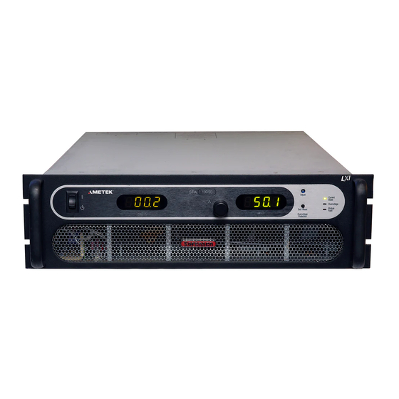
SECTION 3 OPERATION CONTROLS AND INDICATORS Refer to Figure 3-1 and the corresponding descriptions below for an explanation of front panel controls and indicators on the SFA Series power supply. Figure 3-1. Front Panel Controls and Indicators (3U model shown) Voltage Display: 3½... - Page 36 Operation Sorensen SFA Series CURRENT MODE Indicator: Green LED lights when in the constant–current mode of operation. When in the constant–current mode, the output current will regulate to the set value and the output voltage will vary with the load. This is the normal operating mode for the SFA.
-
Page 37: Figure 3-2. Rear Panel Connectors (3U Model Shown)
Sorensen SFA Series Operation Refer to Figure 3-2 and the corresponding descriptions below for an explanation of rear panel connectors. Figure 3-2. Rear Panel Connectors (3U model shown) DC OUTPUT: Positive (+) and negative (–) outputs. Threaded studs for 5-15kW models; bus bars for 20-30kW models. -
Page 38: Shaft Lock (Option)
Operation Sorensen SFA Series 3.1.1 HAFT PTION This option replaces the standard control knob with a two-piece shaft lock. This is installed over the current adjustment potentiometer shaft to prevent rotating under conditions of shock, vibration, or accidental contact. For adjustment, the following steps apply: 1. -
Page 39: Floating And Polarized Output
Sorensen SFA Series Operation This section provides an overview of front panel operation and initial functional tests of the power supply. 3.2.1 LOATING AND OLARIZED UTPUT The SFA Series supply can be set up for a Positive or Negative supply, as well as standard operation as a floating output supply. -
Page 40: Current Mode Operation
Operation Sorensen SFA Series 3.2.3 URRENT PERATION When the supply is in the Current Mode (the default mode for the SFA Series), the output current of the supply is controlled by the Current knob on the front panel or by the remote current input (see Section 3.3). To verify operation in current mode, follow the steps below: 1. -
Page 41: Analog Control Connector (J1)
Sorensen SFA Series Operation present setting of the OCP limit. The factory default setting is approximately 110% of the maximum rated output of the supply. 5. While holding down the Set/Reset button, use a small adjustment screwdriver to adjust the OCP setting by turning the 4-turn recessed adjust potentiometer counterclockwise. -
Page 42: Figure 3-4. Analog Control Connector (J1) Pin-Out
Operation Sorensen SFA Series CAUTION! This option is not intended to allow operation of the power supply at excessive voltages. Refer to Section 2 INSTALLATION for maximum terminal voltages. Following are Figure 3-4 with the connector's pin-out diagram, and Table 3–1 with ANALOG CONTROL connector designations and functions: Figure 3-4. - Page 43 Sorensen SFA Series Operation Schematic Electrical Functional Description Symbol Chars. Not Used Not Used Remote current programming using a 0-5 VDC source. IP 5V Zin ~ 10kΩ Do not exceed 13.3 VDC. Zout ~ 0-5 VDC (0-100%) front panel current control monitor output.
-
Page 44: Table 3-1. Analog Control Connector (J1), Designations And Functions
Operation Sorensen SFA Series Schematic Electrical Functional Description Symbol Chars. Not Used Not Used 1 milliamp current source for remote current programming ~ 10.8V using resistance. 0-5k ohm resistor referenced to common IP RES compliance will program the output from 0-100%. -
Page 45: Remote Current Programming
Sorensen SFA Series Operation REMOTE CURRENT PROGRAMMING Remote current programming is used for applications that require the output current be programmed (controlled) from a remote source. An external resistance or external voltage source may be used as a programming device. -
Page 46: Remote Sensing
Operation Sorensen SFA Series model, each 100 millivolts of programming voltage equals 3 amps of output current. See Figure 3–6 for connection requirements. 16 IP 10V COM 6 IP 5V 10 23 IP RTN 0-5 VDC 0-10 VDC VOLTAGE VOLTAGE... -
Page 47: Figure 3-7. Remote Sensing Operation At The Load
Sorensen SFA Series Operation Figure 3–7. Remote Sensing Operation at the Load * * For accurate measurements through remote voltage readback and front panel voltage meter display. 3-13 M550292-01 Rev G... -
Page 48: Remote Output On/Off Control
Operation Sorensen SFA Series REMOTE OUTPUT ON/OFF CONTROL Remote on/off control may be accomplished by contact closure or by an isolated external AC/DC or TTL/CMOS voltage source. 1. Remote on/off by contact closure. Output is on when contacts (J1-5 and J1-6) are closed. See Figure 3–8 for connection requirements. -
Page 49: Remote Overcurrent Setpoint
Sorensen SFA Series Operation 14 ISO TTL/CMOS ISO RTN 2 Figure 3–10. Remote On/Off Using Isolated TTL/CMOS Voltage Supply REMOTE OVERCURRENT SETPOINT CAUTION! Do not program the remote overcurrent set point greater than 10% (5.5V) above the power supply rated current (except as noted) as internal power supply damage may occur. -
Page 50: Remote Shutdown (S/D)
Operation Sorensen SFA Series REMOTE SHUTDOWN (S/D) A remote +12 VDC voltage can be connected externally between terminals J1- 18 (S/D Fault) and J1-24 (COM) to disable, i.e., shut down the output of the power supply. Disabling or opening the +12 VDC signal will allow the unit to revert to normal operation. -
Page 51: Figure 3-13. Master/Slave Connection
Sorensen SFA Series Operation Figure 3–13. Master/Slave Connection NOTE: The OCP circuit remains active for all units in parallel operation. If the units are set to different OCP levels, the paralleled system will trip according to the lowest setting. For ease of use, adjust the OCP levels for the slaves to maximum and adjust the master OCP level to the desired setting. - Page 52 Operation Sorensen SFA Series This page intentionally left blank. 3-18 M550292-01 Rev G...
-
Page 53: Verification And Calibration
SECTION 4 VERIFICATION AND CALIBRATION INTRODUCTION This section provides verification and calibration procedures for the standard SFA Series power supplies and isolated analog control (option). 4.1.1 ERIFICATION AND ALIBRATION YCLE It is recommended that the power supply be calibrated and/or verified once each year of operation. -
Page 54: Standard Verification And Calibration Procedure
Verification and Calibration Sorensen SFA Series SHUNT Figure 4-1. Precision Current Shunt STANDARD VERIFICATION AND CALIBRATION PROCEDURE All calibration potentiometers can be adjusted through access holes in the top cover of the SFA Series unit. It is not necessary to remove the top cover to perform the calibration procedures. -
Page 55: Resistor Programming Current Sources
Sorensen SFA Series Verification and Calibration 10. Verify the unit is set to 10% ± 0.8% of full-scale output current. If necessary, adjust R55 for 10% of full-scale current on the shunt. 11. Repeat the steps above as required to obtain the required accuracy. -
Page 56: Current Mode
Verification and Calibration Sorensen SFA Series 4.3.1 URRENT 1. Set the SFA Series unit to operate in remote current programming mode using an external 0-5 Vdc voltage source as shown in Figure 3–6 in Section 3.3 Remote Current Programming. 2. Attach a precision meter across the shunt Kelvin terminals. -
Page 57: Figure 4-2. Potentiometer Locations
Sorensen SFA Series Verification and Calibration STANDARD CALIBRATION ADJUSTMENT R71 = IPRES (1mA) Adjust R87 = Voltage Meter Adjust R86 = Current Meter Adjust R69 = 100% Current Adjust R55 = Zero Current Adjust ISOLATED ANALOG (OPTION) CALIBRATION ADJUSTMENT R86 = Voltage Meter Adjust... - Page 58 Verification and Calibration Sorensen SFA Series This page intentionally left blank. M550292-01 Rev G...
-
Page 59: Maintenance
SECTION 5 MAINTENANCE INTRODUCTION This chapter contains preventive maintenance information for the SFA Series power supplies. WARNING! All maintenance that requires removal of the cover of the unit should only be done by properly trained and qualified personnel. Hazardous voltages exist inside the unit. -
Page 60: Table 5-1. Recommended Annual Inspection
Maintenance Sorensen SFA Series An annual inspection of the SFA Series unit is recommended. Table 5–1 lists the visual inspection checks to be performed, and the corrective action to be taken. Table 5–1. Recommended Annual Inspection Item Inspect For Corrective Action... -
Page 61: Fuses
Sorensen SFA Series Maintenance FUSES There are no user replaceable components in the power supply. WARNING! Only properly trained and qualified personnel should remove the cover from the power supply. Service, fuse verification, and connection of wiring to the chassis must be accomplished at least five minutes after power has been removed via external means;... - Page 62 Maintenance Sorensen SFA Series This page intentionally left blank. M550292-01 Rev G...
- Page 63 INDEX Mounting Hardware, 2-3 Circuit Breaker Requirements, 2-2, 2-5 Controls and Indicators, 3-1 Operation Analog Control (J1), 3-7 Current Mode, 3-6 Current Mode Local, 3-4 Operation, 3-6 Master/Slave, 3-16 Verification and Calibration, 4-2 Parallel, 3-16 Remote Current Programming, 3-11 Remote Output On/Off Control, 3-14 Remote Overvoltage Setpoint, 3-15 Fuses, 5-3 Remote Sensing, 3-12...
- Page 64 Index Sorensen SFA Series Setup, 3-5 Ventilation, 2-3 Shaft Lock, 3-4 Verification and Calibration, 4-2 Specifications, 1-2 Current Mode, 4-2 Current, 1-4 Electrical Characteristics, 1-3 Environmental Characteristics, 1-2 Wire Size, 2-6 Noise, 1-4 Physical Characteristics, 1-5 Ripple, 1-4 Voltage, 1-4...
Need help?
Do you have a question about the Sorensen SFA Series and is the answer not in the manual?
Questions and answers