Table of Contents
Advertisement
Quick Links
Advertisement
Table of Contents

Related Manuals for Ametek Sorensen ASA Series


Summary of Contents for Ametek Sorensen ASA Series
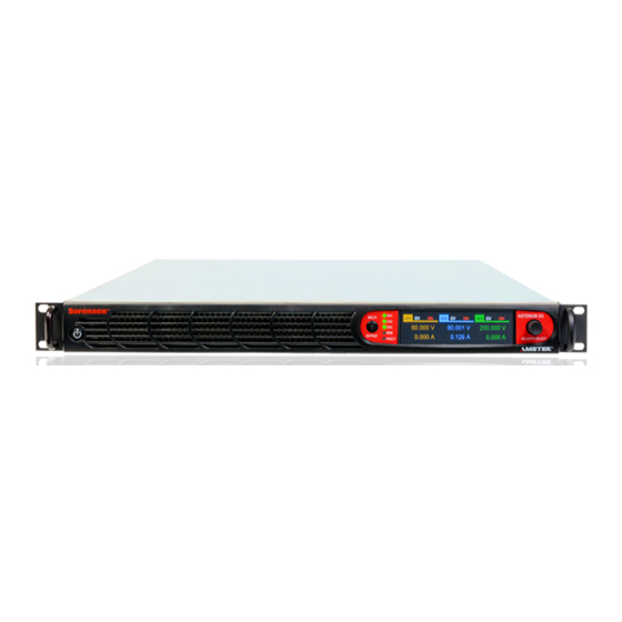
- Page 1 Asterion DC Multi Output ASA Series Operation Manual www.powerandtest.com...
- Page 3 AMETEK Programmable Power, Inc., a unit of AMETEK Electronic Instruments Group (a division of AMETEK, Inc.), is a global leader in the design and manufacture of precision, programmable power supplies for R&D, test and measurement, process control, power bus simulation and power conditioning applications across diverse industrial segments.
- Page 4 AMETEK will, at its expense, deliver the repaired or replaced Product or parts to the Buyer. Any warranty of AMETEK will not apply if the Buyer is in default under the Purchase Order Agreement or where the Product or any part thereof: •...
- Page 5 Neither AMETEK Programmable Power Inc., San Diego, California, USA, or any of the subsidiary sales organizations, can accept any responsibility for personnel, material or inconsequential injury, loss or damage that results from improper use of the equipment and accessories.
- Page 6 SAFETY SYMBOLS WARNING: Electrical Shock Hazard HAZARD: Strong oxidizer GENERAL WARNING/CAUTION: Read the accompanying message for specific information. BURN HAZARD: Hot Surface Warning. Allow to cool before servicing. DO NOT TOUCH: Touching some parts of the instrument without protection or proper tools could result in damage to the part(s) and/or the instrument. TECHNICIAN SYMBOL: All operations marked with this symbol are to be performed by qualified maintenance personnel only.
- Page 7 FCC NOTICE This equipment has been tested and found to comply with the limits for a Class A digital device, pursuant to part 15 of the FCC Rules. These limits are designed to provide reasonable protection against harmful interference when the equipment is operated in a commercial environment.
- Page 8 ABOUT THIS MANUAL AND REGULATORY COMPLIANCE This manual has been written for the Asterion DC Multioutput Series of power supplies, which have been designed and certified to meet the Low Voltage and Electromagnetic Compatibility Directive Requirements of the European Community. These models have been designed and tested to meet the Electromagnetic Compatibility directive (European Council directive 2014/30/EU;...
-
Page 9: Table Of Contents
Contents OVERVIEW ............1-1 General Description ..................1-1 Specifications ....................1-5 1.2.1 Output Power ....................1-5 1.2.2 ASA Series Output Voltage and Current Ratings ........... 1-5 1.2.3 Resolution Specifications ................1-9 1.2.4 Remote Sense ....................1-9 (1)(2) 1.2.5 DC Output Programming, Readback and Regulation Specifications .. - Page 10 Asterion DC Multioutput ASA Series Operational Manual 2.8.5 3-Phase AC Input Operation ................2-12 DC Output and Remote Sense power connections........2-13 2.10 Wire Gauge Selection................. 2-15 2.10.1 Wire Size ......................2-15 2.11 Load Considerations .................. 2-17 2.11.1 Inductive and Stored-Energy Loads .............2-17 2.12 Rear Panel User Interface Connectors .............
- Page 11 Asterion DC Multioutput ASA Series Operational Manual 3.5.4 Constant-Power Mode ..................3-95 REMOTE EXTERNAL USER INTERFACE CONTROL ..............4-1 Introduction ....................4-1 Remote Inhibit (Switch/Relay Contact Closure) ......... 4-5 Remote Output ON/OFF Control by External Source......... 4-7 Trigger Functions ..................4-9 4.4.1 Voltage Ramp ....................
- Page 12 Asterion DC Multioutput ASA Series Operational Manual LIST OF TABLES Table 1-1: Voltage Model for ASA series ..............1-4 Table 1-2: Output Power for ASA Series ..............1-5 Table 1-3: Channel ratings for Asterion DC Multioutput ASA Model Series ....1-5 Table 2-1: Ship Kit Details....................
- Page 13 Asterion DC Multioutput ASA Series Operational Manual LIST OF FIGURES Figure 1-1: Asterion DC Series Power Supply, 1U Models ........... 1-1 Figure 1-2: Asterion DC Multioutput ASA Series Model Number Decoding ....1-3 Figure 1-3 ASA Series Extended Wide Range Channels Voltage Vs Current Characteristics ......................
- Page 14 Asterion DC Multioutput ASA Series Operational Manual Figure 3-15: HOME Screen Menu 3 ................3-39 Figure 3-16: Dashboard Screen – Channel 1 ............. 3-41 Figure 3-17: Dashboard Screen – Channel 2 ............. 3-41 Figure 3-18: Dashboard Screen – Channel 3 ............3-41 Figure 3-19: Output Voltage as EXT Reference Mode for Channel 1 ......
- Page 15 Asterion DC Multioutput ASA Series Operational Manual Figure 3-57: PONS Menu Screen-2 without Analog Interface feature ......3-56 Figure 3-58: PONS - Output Settings Screen ............. 3-57 Figure 3-59: PONS - Output State Screen ..............3-58 Figure 3-60: PONS - Regulation Mode Screen ............3-58 Figure 3-61: PONS - User V/I Limits Screen –...
- Page 16 Asterion DC Multioutput ASA Series Operational Manual Figure 3-99: Control Interface Menu Screen with Analog disabled ......3-77 Figure 3-100: RS232 Home Screen ................3-77 Figure 3-101: RS232 Setting Screen ................. 3-78 Figure 3-102: RS232 Configure Screen ..............3-78 Figure 3-103: LAN Menu Screen................3-78 Figure 3-104: LAN Screen (Settings) .................
- Page 17 Asterion DC Multioutput ASA Series Operational Manual Figure 3-141: Clear Fault Screen ................3-90 Figure 3-142: Local/Remote Screen ................3-92 Figure 3-143: Constant-Power Example ..............3-95 Figure 4-1: External User Interface Connector ............. 4-1 Figure 4-2: Output On/Off Control by Contact Closure channel 1 ......... 4-6 Figure 4-3: Output On/Off Control by Contact Closure channel 2 .........
-
Page 19: Overview
OVERVIEW General Description The Sorensen Asterion DC multioutput ASA Series of DC power supplies is a three- channel output supply in 1U Full rack size. Channel output voltage/ current ratings are selectable when ordering the power supply. Asterion DC multioutput ASA Series combines intelligence and flexibility to create an advanced platform of DC solutions. - Page 20 Asterion DC Multioutput ASA Series Operational Manual the remote Virtual Panels control as you could working directly with the unit’s front panel. This source also comes with the Optional Isolated Analog Programming Inputs and Monitor Outputs for output voltage and current. The independent analog inputs are available for each output channel, and they are isolated from channel power outputs.
-
Page 21: Figure 1-2: Asterion Dc Multioutput Asa Series Model Number Decoding
Asterion DC Multioutput ASA Series Operational Manual XXX XXX XXX X - X X X X SERIES ASA - Asterion DC Multioutput, 600 W/ Channel, 1800 W Total CHANNEL-1 VOLTAGE Enter 3 Digit Voltage, Select from Table 1-1 for ASA Series CHANNEL-2 VOLTAGE Enter 3 Digit Voltage, Select from Table 1-1 for ASA Series CHANNEL-3 VOLTAGE... -
Page 22: Table 1-1: Voltage Model For Asa Series
Asterion DC Multioutput ASA Series Operational Manual 3 Digit Voltage for ASA series 000 – Channel Not mounted only applicable for Channel 3 Table 1-1: Voltage Model for ASA series M330516-01... -
Page 23: Specifications
Asterion DC Multioutput ASA Series Operational Manual Specifications The following sections provide electrical, environmental, and physical specifications for the Asterion DC Multioutput Series power supplies. Unless otherwise noted, the specifications are valid under the following conditions: a. Ambient temperature of 25 5C, after a 30-minute warm-up, and at fixed AC input line and load. -
Page 24: Figure 1-3 Asa Series Extended Wide Range Channels Voltage Vs Current
Asterion DC Multioutput ASA Series Operational Manual Figure 1-3 ASA Series Extended Wide Range Channels Voltage Vs Current Characteristics The voltage and current characteristics of the 600 W, 200 V, 17 A is given in Figure 1-5. For any given voltage, the maximum supported current is described. There are three distinct regions, the red line shows the maximum supported current for a given model green line shows the maximum full-scale voltage for the model and the blue curved section shows the models power limit. -
Page 25: Figure 1-4 Asa Series 600W, 60 V, 42 A Voltage Vs Current Characteristics
Asterion DC Multioutput ASA Series Operational Manual Figure 1-4 ASA Series 600W, 60 V, 42 A Voltage Vs Current Characteristics Figure 1-5 ASA Series 600 W, 200 V, 17 A Voltage Vs Current Characteristics M330516-01... -
Page 26: Figure 1-6 Asa Series 600 W, 80 V, 22 A Voltage Vs Current Characteristics
Asterion DC Multioutput ASA Series Operational Manual Figure 1-6 ASA Series 600 W, 80 V, 22 A Voltage Vs Current Characteristics Figure 1-7 ASA Series 600 W, 400 V, 6 A Voltage Vs Current Characteristics M330516-01... -
Page 27: Resolution Specifications
Asterion DC Multioutput ASA Series Operational Manual 1.2.3 Resolution Specifications Remote digital Resolution Front panel Interface Voltage Output programming resolution 0.012% of full scale 4 Digits Current Output programming resolution 0.012% of full scale 4 Digits Power Output programming resolution 0.012% of full scale 4 Digits Overvoltage programming resolution... -
Page 28: Output Ripple, Noise And Transient Specifications
Asterion DC Multioutput ASA Series Operational Manual DC Regulation Characteristics- Constant Voltage Mode Maximum line regulation +/- 0.01% of rated voltage Maximum load regulation +/- 0.02% of rated voltage Temperature Drift +/- 100 PPM / degree Celsius Stability +/- 0.05% of rated voltage DC Regulation Characteristics- Constant Current Mode Maximum line regulation +/- 0.05% of rated current... -
Page 29: Ac Input Specifications
Asterion DC Multioutput ASA Series Operational Manual 1.2.7 AC Input Specifications Model 600 W Per Channel Total 1800 W for 3 Channels in a Chassis Input Option “C”: 3 phase, 3 wire + Gnd or 1 Phase, 2 wire + Gnd Nominal Rating Range for 3 phase 3 wire+ Gnd: 200- 240 VAC, 3 Phase, Line- Line. -
Page 30: Operational Characteristics
Asterion DC Multioutput ASA Series Operational Manual Input Option “C”: 3 phase, 3 wire + Gnd: 55 A Peak @ 264 V L-L Input Option “C”: 1 phase, 2 wire + Gnd, Low line: 30 A Peak @ 132 V L-N Input Option “C”: 1 phase, 2 wire + Gnd, High line: 55 A Peak @ 264 V L-N Inrush Current, Input Option “D”, 3 phase, 3 wire + Gnd: 55 A Peak @ 456 VAC L-L... -
Page 31: Front Panel Controls/Indicators
Asterion DC Multioutput ASA Series Operational Manual Constant Voltage (CV), Constant Current (CC) and Constant Power (CP) Output Modes of modes are supported. Operation User-selectable fold back mode CV/CC/CP or CV or CC or CP. Enhance front panel touch display for the unit enables control and programming of output channels. -
Page 32: Remote Isolated External User Control I/O Signal Interface Characteristics1-14
Asterion DC Multioutput ASA Series Operational Manual Touch-Panel, TFT color LCD display with menu-based control; Display size: 1U models, 3.9” diagonal Rotary encoder for menu navigation and parameter adjustment and entry, with integrated selection switch. POWER switch: turns unit on/off. OUTPUT switch: turns output on/off of the selected channel. -
Page 33: Remote Control Digital Interface Characteristics
Asterion DC Multioutput ASA Series Operational Manual Signal connects to Open-anode of opto-isolator diode with internal 1kΩ series resistor internal to power supply. Voltage Rating: Maximum 24V, Minimum -5V Low state: 0.3 V max, High State 2.7V min Output signal, active-high; synchronization pulse of 10 ms when a change in the output occurs. - Page 34 Asterion DC Multioutput ASA Series Operational Manual Parallel interface complies with IEEE-488.1, IEEE-488.2, and the SCPI command specification; IEEE-488 (Option) command execution response time, 10 ms, typical; connector: IEEE-488.1 compliant. Firmware Firmware can be upgraded through the LAN interface. Upgrade M330516-01 1-16...
-
Page 35: Optional Remote Isolated Analog Programming Interface Characteristics
Asterion DC Multioutput ASA Series Operational Manual 1.2.12 Optional Remote Isolated Analog Programming Interface Characteristics Each channel of the Asterion DC Multioutput ASA Series is provided with 8-Pin connector for the analog programming functions. Refer to operation manual for the connector and pin details. Function Characteristics Independent Signal inputs for output voltage and current programming using... -
Page 36: Output Isolation
Asterion DC Multioutput ASA Series Operational Manual 1.2.14 Output Isolation Parameter Specification Output terminal Positive (+Ve) and ±600 V , maximum, with respect to chassis ground. Negative (-Ve) ±600 V , maximum; optional Isolated Analog Isolated Analog interface Signals and programming and external user interface signals are External User Control I/O interface to isolated from negative output terminal;... -
Page 37: Regulatory Agency Compliance
Asterion DC Multioutput ASA Series Operational Manual 1.2.17 Regulatory Agency Compliance Paramete Specification CE marked for EMC Directive 2014/30/EU per EN61326-1:2013, Class-A for emissions and immunity as required for the EU CE Mark. Safety CSA NRTL certified for US and Canada to CAN/CSA-C22.2 No. 61010-1-12, UL 61010-1 Third Edition. -
Page 38: Figure 1-9: Rear Panel Connectors With Gpib Option
Asterion DC Multioutput ASA Series Operational Manual Figure 1-9: Rear Panel Connectors with GPIB Option M330516-01 1-20... -
Page 39: Overall Dimensions Drawing
Asterion DC Multioutput ASA Series Operational Manual 1.2.19 Overall Dimensions Drawing Figure 1-10 Dimensional Drawing M330516-01 1-21... -
Page 41: Installation
If any damage is evident, immediately contact the carrier that delivered the unit and submit a damage report. Failure to do so could invalidate future claims. Direct repair issues to AMETEK Customer Service Department at 858-458-0223 (local) or 1-800- 733-5427 (toll free in North America). -
Page 42: Mechanical Installation
Qty would be 16 Nos for the two-channel power supply, Item No 7 is supplied when only Isolated Analog Programming option is Ordered Table 2-1: Ship Kit Details Note: If any of these parts are missing, contact AMETEK Customer Service Department at 858-458-0223 (local) or 1-800-733-5427 (toll free). Optional accessories: 1. -
Page 43: Rack Mounting
The rack mounting slide kit, part number 5330201-01R consists of the following items: Part Number Description Item # JONATHAN 510QD-24 105-510-24 RACK SLIDES,FRICTION,24 IN,SS AMETEK 9330325-01R BRKT, RACKSLIDE -DYN 110-800-06 SCREW,8-32 X .375,PFH100,LK,SS 112EN04-01 NUT,8-32,W/CONE WASHER,KEP,CS 110GS04-08 SCREW,10-32 X .500,SEMS,PPH,CS... -
Page 44: Chassis Removal From Rack
Asterion DC Multioutput ASA Series Operational Manual 3. Adjust the location of the mounting brackets as required for the rack cabinet vertical rails utilized. 4. Mount the cabinet sections of the slides, item #1C, (with brackets already installed) into the cabinet using appropriate hardware (e.g., the screws and nuts supplied, item #6 and item#7, or user-supplied bar-nuts, cage-nuts, clip- nuts), while ensuring that they are level, front to back and left to right, on the cabinet rails. -
Page 45: Outline Drawings
Asterion DC Multioutput ASA Series Operational Manual from full extension, depress the flat steel spring (located on the slides) inward, and push the chassis back. When the chassis is at full extension, the flat springs are located behind the front rack rails. -
Page 46: Figure 2-2: Installation Drawing
Asterion DC Multioutput ASA Series Operational Manual Figure 2-2: Installation Drawing Figure 2-3 shows the rear panel view of the power sources and the location of the connectors with GPIB option. M330516-01... -
Page 47: Figure 2-3: Rear Panel View With Gpib Option
Asterion DC Multioutput ASA Series Operational Manual Figure 2-4 shows the installation of the rear panel protective covers for the AC input and DC Output terminations. The components comprising these covers are supplied in the ship kit. CAUTION! M4 0.7 KEPS nuts - Maximum tightening torque is 1.1Nm (10 lb-in.). Figure 2-3: Rear Panel View with GPIB option Figure 2-4: Rear Panel Protective covers installation M330516-01... -
Page 48: Rear Panel Input/ Output Connections
Asterion DC Multioutput ASA Series Operational Manual Rear Panel Input/ Output Connections Figure 2-3 shows the rear panel view of the power source and locations of the rear panel connector for the rear panel view of the 1U model power source showing the location of the connectors. -
Page 49: Ac Input Power Connection
Asterion DC Multioutput ASA Series Operational Manual RS-232C connector for remote digital control; External digital RS-232C connector see section 2.12.3. interface USB type B connector for remote digital control; External digital USB Connector see section 2.12.4. interface Ethernet connector for remote digital control; see External digital Ethernet connector section 2.12.5. -
Page 50: Ac Input Safety Disconnect Device
Asterion DC Multioutput ASA Series Operational Manual 2.8.2 AC Input Safety Disconnect Device The Multioutput Asterion DC Series power source front panel POWER switch does not disconnect the AC input line from the unit. Ensure that an appropriately rated safety disconnect device is incorporated in the installation that will provide isolation from the AC input when the device is opened. -
Page 51: Table 2-4: Ac Input Connector Pinout And Safety-Ground
Asterion DC Multioutput ASA Series Operational Manual A 1-Phase input is connected to terminals L1/L2 or L2/L3 (do not connect a 1-Phase input between L1/L3), while a 3-Phase input is connected to L1/L2/L3 (a connection to neutral is not utilized with 3-Phase input). The connector has compression terminals with female contacts. -
Page 52: 1-Phase Ac Input Operation- Only Supported In Input Ac Voltage Type
Asterion DC Multioutput ASA Series Operational Manual 2.8.4 1-Phase AC Input Operation- Only Supported in Input AC voltage type “C” Connect the utility AC mains wires to the rear panel AC input connector terminals, L1/L2, L2/L3, or L1/L3. Ensure that the voltage does not exceed 264 VAC. The power source does not require a neutral connection, so the input could be between any two lines that have a voltage that does not exceed 264 VAC. -
Page 53: Dc Output And Remote Sense Power Connections
Asterion DC Multioutput ASA Series Operational Manual CAUTION! Input AC voltage type “E”: Do not connect an AC voltage that is greater than 528 VAC, line-to-line for 3-Phase input. Exceeding the maximum AC input voltage could result in damage to the unit. Single phase input is not supported with voltage type “E”... -
Page 54: Table 2-7: Dc Output And Remote Sense Connector Type
Asterion DC Multioutput ASA Series Operational Manual Connector Type Chassis connector header: Phoenix P/N 1720835; 6-position, compression terminals; Mating connector: Phoenix P/N 1777875; compression terminals; housing retained to header with screws; DC Output and Wire stripping length: 10 mm (0.39”); Remote Sense Tightening torque: 0.7 Nm, min (6.1 lb-in) to 0.8 Nm, max (7 lb-in);... -
Page 55: Wire Gauge Selection
Asterion DC Multioutput ASA Series Operational Manual Output voltage sensing is user-selectable to be either local sense or remote sense. Sensing provides the signal for measurement of the output voltage and determines the physical point where the output voltage is precisely regulated. Local and Remote sense both are at the rear panel output connector, while remote sense is at the load, through a cable connection from the rear panel remote sense Pin S+ and S-. -
Page 56: Table 2-8: Minimum Wire Size
Asterion DC Multioutput ASA Series Operational Manual Size Temperature Rating of Copper Conductor 60°C 75°C 90°C Types: TW, UF Types: RHW, THHW, Types: TBS, SA, SIS, THW, THWN, XHHW, FEP, FEPB, MI, RHH, USE, ZW THHN, THHW, XHH, XHHW Current Rating, A(RMS) −... -
Page 57: Load Considerations
Asterion DC Multioutput ASA Series Operational Manual In high performance applications requiring high inrush/ transient currents, additional consideration is required. The cable wire gauge must accommodate peak currents developed at peak voltages, which might be up to five times the RMS current values. An underrated wire gauge adds losses, which alter the inrush characteristics of the application and thus the expected performance. -
Page 58: Rear Panel User Interface Connectors
Asterion DC Multioutput ASA Series Operational Manual the output: Connect the cathode to the positive output and the anode to return. Where positive load transients, such as back EMF from a motor might occur, or stored energy is present such as a battery, a second blocking diode in series with the output is recommended to protect the power supply. -
Page 59: Table 2-10: Analog Programming Connector Type
Asterion DC Multioutput ASA Series Operational Manual Figure 2-10: Analog Programming connector Connector Type Miniature mate and lock type, TE Connectivity P/N 2-1445055-8 Remote Analog programming Mating Connector, TE Connectivity P/N 1445022-8 Crimp Pin, TE Connectivity P/N 794610-1 Table 2-10: Analog Programming Connector Type Function Characteristics Independent Signal inputs for output voltage and current programming... - Page 60 Asterion DC Multioutput ASA Series Operational Manual Range: Full scale Voltage could be set by the user from 5V to 10V. Input impedance: 20kΩ, typical Remote control input for voltage programming using a resistance connected between this pin and signal return. Current Source of 1 mA is internally connected to this pin to enable resistance programming.
-
Page 61: Remote External User Control Interface
Asterion DC Multioutput ASA Series Operational Manual Minimum recommended Load: 100kΩ, typical Maximum Load: 20kΩ Table 2-12: Analog Programming Connector Pin out The pinout function mentioned in Table 2-12 is identical for each channel connectors. To program desired channel corresponding analog channel connector to be utilized. CAUTION! Return signal of all the three channels are shorted internal to the power supply. -
Page 62: Table 2-14: External User Control Interface Characteristics
Asterion DC Multioutput ASA Series Operational Manual Switch/Relay contact closure or direct short from this terminal to signal return is required to Turn ON/OFF the power supply. Opening the contact would shut down the output and would be latched after reclosing the contact, user Remote Inhibit Input needs to turn ON the output. - Page 63 Asterion DC Multioutput ASA Series Operational Manual Signal connects to Open-anode of opto-isolator diode with 1kΩ series resistor internal to power supply. Signal return: Pin 8 Voltage Rating: Maximum 24V, Minimum -5V Low state 0.3V max, High State 2.7V min. Output signal, active-high;...
- Page 64 Asterion DC Multioutput ASA Series Operational Manual issuing the SCPI command OUTP<n>:PROT:CLE or by clearing the fault from the front panel screen. Remote circuit must sink up to 10mA from 5 VDC to enable. Signal return: Pin 8 RETURN Return/GND. Pins 8,17 and 26 are shorted internal to the power supply. No Connection Channel-2 Signals (Pin number 10 to 18) Input signal, TTL active-high;...
- Page 65 Asterion DC Multioutput ASA Series Operational Manual Signal return: Pin 17 Voltage Rating: Maximum 30V, Minimum 3V for Active High, Sink Current: 50mA. Switch/Relay contact closure or direct short from this terminal to signal return is required to enable/disable the output of the power supply. Opening the contact would disable the output.
-
Page 66: Rs-232C Serial Interface
Data Terminal Equipment (DTE) should be straight-through (one-to- one contact connections). For EMC considerations a ferrite core can be added to the cable Ametek P/N: 991-642-28, Manufacturer P/N: CS28B0642. Refer to the DC- Asterion Multioutput Series Programming Manual P/N M330517-01 distributed on the CD, M550008-01 for establishing communication from the computer. -
Page 67: Usb Interface
Table 2-19 for pin descriptions. A standard USB cable between the Asterion Series power source and a computer should be used. For EMC considerations a ferrite core can be added to the cable Ametek P/N: 991-642-28, Manufacturer P/N: CS28B0642. Refer to the DC-Asterion Multioutput Series Programming Manual P/N M330517-01 distributed on the CD, M550008-01 for establishing communication from the computer. -
Page 68: Lan Interface
DC-Asterion Multioutput Series Programming Manual P/N M330517- 01distributed on the CD, M550008-01. For EMC considerations a ferrite core can be added to the cable Ametek P/N: 991-642-28, Manufacturer P/N: CS28B0642. Figure 2-14: LAN Interface 8P8C Modular Connector Connector... -
Page 69: Gpib Interface
Asterion DC Multioutput ASA Series Operational Manual EIA/TIA 568B Pin # Ethernet Signal EIA/TIA 568A Crossover Transmit/Receive Data 3 - Brown with white stripe or Brown with white stripe or solid brown solid brown Table 2-21: LAN Interface 8P8C Modular Connector Pinout 2.12.6 GPIB interface A GPIB connector is located on the rear panel for remote control;... -
Page 70: Table 2-23: Gpib Interface Connector Pinout
Asterion DC Multioutput ASA Series Operational Manual Pin # GPIB Signal Description DIO6 Data Input/ Output bit DIO7 Data Input/ Output bit DIO8 Data Input/ Output bit Remote Enable Digital Ground Digital Ground Digital Ground Digital Ground Digital Ground Digital Ground Digital Ground Table 2-23: GPIB Interface Connector Pinout M330516-01... -
Page 71: Operation
Asterion DC Multioutput ASA Series Operational Manual OPERATION Introduction The Asterion Multioutput DC ASA Series is operated from the intuitive, easy-to-use front panel touch screen display. Provides Quick access to output programming parameters, measurements, ramp, configuration, control interface and system settings from the touch screen interface. -
Page 72: Basic Front Panel Operation
Asterion DC Multioutput ASA Series Operational Manual Two–position pushbutton switch turns the source on and off. WARNING! ON/OFF Switch OFF position does not remove AC input from internal circuits. Disconnect external AC input before servicing unit Momentary switch that toggles the selected channel output power OUTPUT ON/OFF Switch ON/OFF. -
Page 73: 3.3.1 Initial Setup
Asterion DC Multioutput ASA Series Operational Manual signals for all the 3 channels connected (Pin-7 shorted to Pin-8 to enable channel-1, Pin- 16 shorted to Pin-17 to enable channel-2, Pin-25 shorted to Pin-26 to enable channel-3) to allow the output to be enabled. WARNING! The power-up factory default state is output enabled, and the output will be energized with the settings of voltage and current at zero. -
Page 74: Figure 3-2: Home Screen With Dashboard Icon Highlighted
Asterion DC Multioutput ASA Series Operational Manual Tapping an Arrow or selecting it with the rotary encoder and clicking the switch, scrolls the screen to the next page. When outside one of the HOME screens, tapping the Home icon will exit that screen and would return to the HOME screen. Refer to Figure 3-3 and Figure 3-2 respectively. -
Page 75: 3.3.3 Touch-Screen Numeric Keypad
Asterion DC Multioutput ASA Series Operational Manual parameter for adjustment, and the screen changes to the numeric keypad that allows value entry; Refer to Figure 3-7. Another way of entering the value is by scrolling to the parameter selection-field and depressing with encoder switch, parameter selection- field active has its border highlighted in bold when selected using the encoder switch;... -
Page 76: 3.3.4 Rotary Encoder
Asterion DC Multioutput ASA Series Operational Manual 3.3.4 Rotary Encoder The rotary encoder provides a secondary way to navigate the display. It is used to select functions, change parameter values, and perform setup. It can be used to move between menu screens and between editable items within an individual menu screen. - Page 77 Asterion DC Multioutput ASA Series Operational Manual The DASHBOARD screen menu has the capability for real-time adjustment of output parameters: the value of the parameters change as the rotary encoder is turned for immediate effect at the output. If the OUTPUT switch is on, the output parameter will change as the encoder is rotated.
-
Page 78: Front Panel Display Menu And Functionality
Asterion DC Multioutput ASA Series Operational Manual Front Panel Display Menu and Functionality 3.4.1 Power-Up Screens At initial power-on, the display shows the Asterion DC Multioutput Splash screen, Refer to Figure 3-9, followed by the Start-Up screen with the manufacturer name, model number, serial number, firmware revisions and last calibration date, Refer to Figure 3-10, and finally the Dashboard screen, Refer to Figure 3-16. -
Page 79: Home Screen Top-Level Menu
Asterion DC Multioutput ASA Series Operational Manual Figure 3-12: Abort Status Screen 3.4.2 Home Screen Top-Level Menu Selecting the Home icon or Up arrow will open the HOME screen. Each menu of a screen could be selected by tapping its associated selection-field box through the touch-screen, or by selecting it with the rotary encoder and depressing (clicking) the rotary encoder SELECT switch. -
Page 80: Dashboard Screen Top-Level Menu
Asterion DC Multioutput ASA Series Operational Manual The following top-level menu choices can be accessed through the touchscreen: Top-Level Screen Menu Menu Description Provides setting and measurement of output parameters: voltage and DASHBOARD current for individual channels. Provides setting of voltage, current, power, Regulation Mode, Output OUTPUT PROGRAM state, and OVP (Over Voltage Protection) for individual channels. - Page 81 Asterion DC Multioutput ASA Series Operational Manual menu that is displayed after power-on, refer to Figure 3-16. The DASHBOARD screen displays settings and measurement for all three channels. Active channel is highlighted by its channel color. First channel’s settings and measurements are in Orange color.
- Page 82 Asterion DC Multioutput ASA Series Operational Manual Figure 3-19: Output Voltage as EXT Reference Mode for Channel 1 Figure 3-20: Output Current as EXT Reference Mode for Channel 2 Figure 3-21: Output Voltage and current as EXT Reference Mode for Channel 3 The following selections are available for each channel in the DASHBOARD screen top-level menu.
- Page 83 Asterion DC Multioutput ASA Series Operational Manual press output button. Specific channel output LED gets turned ON and toggling output button again, LED gets turned OFF. 3.4.3.1 R ARAMETER DJUSTMENT The DASHBOARD screen menu provides the capability for output parameter entry that has real-time, immediate effect on the output.
-
Page 84: Output Program
Asterion DC Multioutput ASA Series Operational Manual Figure 3-24: Default Screen With the understanding of the dashboard screen features, user can perform basic functionality and verify the output voltage and output current in various modes of operation as described in Section 3.4.3 (Dashboard Screen). 3.4.4 Output Program The OUTPUT PROGRAM provides setting of output related items such as individual... - Page 85 Asterion DC Multioutput ASA Series Operational Manual Figure 3-26: Output Settings Screen – Channel 1 Figure 3-27: Output Settings Screen – Channel 2 Figure 3-28: Output Settings Screen – Channel 3 The following choices are available in the Output Settings screen. Functions that accept a numeric value require that the value be within the allowed range, otherwise, an error will be generated, and the value will not be accepted.
- Page 86 Asterion DC Multioutput ASA Series Operational Manual 3.4.4.2 O UTPUT TATE CREEN Output state screen provides the functionality to turn Output of each channel either ON or OFF. Selecting Output state submenu in OUTPUT PROGRAM screen (refer Figure 3-25) opens up output state screen as below (Refer to Figure 3-29, Figure 3-30 and Figure 3-31).
- Page 87 Asterion DC Multioutput ASA Series Operational Manual Figure 3-32: Regulation Mode Screen – Channel 1 Figure 3-33: Regulation Mode Screen – Channel 2 Figure 3-34: Regulation Mode Screen – Channel 3 Entry Description CC/CV/CP Sets the Regulation Mode as CC/CV/CP for selected channel. Supply switches between the CC (constant current), CV (constant voltage) and CP (constant power) modes based on the load conditions, without making the output to zero.
-
Page 88: Measurements
Asterion DC Multioutput ASA Series Operational Manual To provide additional protection for the load, voltage, and current limits may be set while in the Constant-Power mode. If the unit cannot regulate to the Constant Power setting due to load conditions, it will regulate either at the voltage or current limit depending on the load demand Note: Constant Power mode is intended primarily for loads with... -
Page 89: Configuration Screen
Asterion DC Multioutput ASA Series Operational Manual Figure 3-36: Measurements Screen Top Level Menu 3.4.6 Configuration Screen This section demonstrates the configuration of power on- settings (PONS), set-up of User V/I Limits, Output Sense, Measurement Settings and Remote Inhibit Settings for individual channels. - Page 90 Asterion DC Multioutput ASA Series Operational Manual Figure 3-39: Configuration Menu screen 2 The following menus are available in the Configuration Screen top-level menu: • Measurement Settings • Remote Inhibit Settings • User V/I Limits • Current Ref. Mode • Voltage Ref.
- Page 91 Asterion DC Multioutput ASA Series Operational Manual 3.4.6.2 R EMOTE NHIBIT External user interface (26 pin connector) provides with remote inhibit inputs for each channel. A contact closure or direct short between remote inhibit terminal and return will allows the Output of power supply to be turned ON. The external user interface connector (26 pin connector) is supplied with a mating connector which has the remote inhibit input output ON/OFF control signals for all the 3 channels connected (Pin-7 shorted to Pin-8 to enable channel-1, Pin-16 shorted to...
- Page 92 Asterion DC Multioutput ASA Series Operational Manual Entry Description Latching When the contact is opened between remote inhibit terminal and return, output is turned off and programmed to zero volts and the output latches in shutdown state. Having configure the channel remote inhibit input to Latching mode and contact opening in the remote inhibit input of channel creates remote inhibit fault in the front panel, user need to clear the fault to come out of the latched state.
- Page 93 Asterion DC Multioutput ASA Series Operational Manual Figure 3-46: User V/I Limit Screen – Channel 3 Entry Description Voltage Sets the power-on default value of voltage user limit in Volts for each channel. The default is PONS User Voltage Limit. Current Sets the power-on default value of output current in Amperes for each channel.
- Page 94 Asterion DC Multioutput ASA Series Operational Manual Figure 3-49: Current Reference Mode channel 3 Entry Description Sets the Current Reference Mode into internal for selected channels Allows user to program the output current through front panel and digital interfaces. Sets the current Reference Mode into external for selected channels. Allows user to program the output current only through the analog programming interface.
-
Page 95: Output On/Off Delay
Asterion DC Multioutput ASA Series Operational Manual Figure 3-52: Voltage Ref Mode channel 3 Entry Description Sets the Voltage Reference Mode into internal for selected channels. Allows user to program the output voltage through front panel and digital interfaces. Sets the Voltage Reference Mode into external for selected channels. Allows user to program the output voltage only through the analog programming interface. -
Page 96: Figure 3-57: Pons Menu Screen-2 Without Analog Interface Feature
Asterion DC Multioutput ASA Series Operational Manual 3.4.6.7 P ON S (PONS) OWER ETTINGS The PONS Menu allows user to set the Power-ON values which is programmed during next power cycle of unit. The top-level menu of PONS is shown in Figure 3-54. if the supply is not provided with analog programming feature following analog interface related menus are inactive (grayed out) from PONS menu screen: PONS –... -
Page 97: Figure 3-58: Pons - Output Settings Screen
Asterion DC Multioutput ASA Series Operational Manual PONS menu contains following sub menu: • PONS – Output Settings • PONS – Output State • PONS – Regulation Mode • PONS – User V/I Limits • PONS – Voltage Reference Mode •... -
Page 98: Figure 3-59: Pons - Output State Screen
Asterion DC Multioutput ASA Series Operational Manual selected channel (refer Figure 3-11). If no action is taken by operator, then output will be turned ON for specific channel. Refer Figure 3-59. Up-arrow will return to PONS menu screen; Refer Figure 3-54. Home button will return to HOME MENU screen 2;... - Page 99 Asterion DC Multioutput ASA Series Operational Manual The PONS User V/I Limits menu allows to set the soft-limits for output voltage, current and power of each channel at power-on of unit. Default value is full scale, refer to Figure 3-61. Up-arrow will return to PONS menu screen;...
- Page 100 Asterion DC Multioutput ASA Series Operational Manual Figure 3-64: PONS – Voltage Ref Mode channel – 1 Entry Description Configures power-on Voltage Ref Mode as internal for selected channels. INT (internal) is the factory default voltage ref Mode. Configures power-on Voltage Ref Mode as external for selected channel.
-
Page 101: Figure 3-66: Pons - Analog Screen
Asterion DC Multioutput ASA Series Operational Manual Sets the Analog programming interface Configurations during UUT Power-ON, refer to Figure 3-66. Up-arrow will return to PONS menu screen; Refer Figure 3-54. Home button will return to HOME MENU screen 2; Refer Figure 3-14. Figure 3-66: PONS - Analog Screen PONS –... -
Page 102: Figure 3-71: Pons - Configure Full Scale Value Channel-1
Asterion DC Multioutput ASA Series Operational Manual PONS - Configure Reference Source: Sets the analog reference source to either Voltage or Resistive during supply power- ON for Selected channel, Refer Figure 3-70. Figure 3-70: PONS – Configure Reference Source channel - 1 Entry Description Voltage... -
Page 103: Figure 3-72: Pons - Configure Full Scale Value Channel-2
Asterion DC Multioutput ASA Series Operational Manual Figure 3-72: PONS – Configure Full Scale Value Channel-2 Figure 3-73: PONS – Configure Full Scale Value Channel-3 Entry Description Full Scale for Voltage: To Set the power-on FSC value of analog voltage program for Selected Channels, default FSC is 10V for Voltage reference source and 10kΩ... -
Page 104: Figure 3-74: Pons - Measurement Settings Screen
Asterion DC Multioutput ASA Series Operational Manual Figure 3-74: PONS - Measurement Settings Screen The Measurement Settings screen has the following fields: Entry Description Volt Avg Samples Sets the number of voltage readings to average in the voltage readback during Unit power-on. Allows to set a value between 1 to 5. -
Page 105: Figure 3-78: Ramp Menu Screen
Asterion DC Multioutput ASA Series Operational Manual Figure 3-77: PONS – Remote Inhibit channel 3 Entry Description Latching Configures power-on Remote Inhibit Mode as Latching for selected channels. Live Configures power-on Remote Inhibit Mode as Live for selected channels. Live is the factory default Remote Inhibit Mode. 3.4.7 Ramp The Ramp Screen provides the functionality to create voltage and current Ramp in... -
Page 106: Figure 3-79: Voltage Ramp Screen
Asterion DC Multioutput ASA Series Operational Manual Figure 3-79: Voltage Ramp Screen The Voltage Ramp menu has the following fields: Entry Description Volt Sets the start voltage for the ramp. To Volt Sets the end voltage for the ramp. Curr Sets the Current limit for the ramp. -
Page 107: Figure 3-81: Voltage Ramp-Screen (Sw Trigger)
Asterion DC Multioutput ASA Series Operational Manual Figure 3-81: Voltage Ramp-Screen (SW Trigger) Waiting for Trig This field is displayed after Initialize button is pressed in HW trigger Mode, refer to Figure 3-82:. This shows that the supply is waiting for an active high pulse of 10ms on the DB26 connector to generate the Voltage Ramp;... - Page 108 Asterion DC Multioutput ASA Series Operational Manual Exit Exits the Voltage Ramp sub menu and return to Ramp Menu, refer to Figure 3-78. Example 1: Creating a Voltage ramp using Software Trigger mode • Select Channel • Set the Volt to 25V •...
-
Page 109: Figure 3-84: Current Ramp Screen
Asterion DC Multioutput ASA Series Operational Manual Pressing Exit button would return to Ramp Menu screen 2; Refer Figure 3-78. Figure 3-84: Current Ramp Screen The Current Ramp menu has the following fields: Entry Description Curr Sets the start current for the ramp. To Curr Sets the end current for the ramp. -
Page 110: Figure 3-86-: Current Ramp-Screen (Sw Trigger)
Asterion DC Multioutput ASA Series Operational Manual Figure 3-86-: Current Ramp-Screen (SW Trigger) Waiting for Trig This field is displayed after Initialize button is pressed in HW trigger Mode, refer to Figure 3-87:. This shows that the supply is waiting for an active high pulse of 10ms on the DB26 connector to generate the Current Ramp each channel individually. -
Page 111: Figure 3-88: Current Ramp-Screen (Abort)
Asterion DC Multioutput ASA Series Operational Manual Figure 3-88: Current Ramp-Screen (Abort) Exit Exits the Current Ramp screen and return to Ramp Menu Screen, refer to Figure 3-78. Example 1: Creating a Current ramp using Software Trigger mode • Select channel •... -
Page 112: Figure 3-89: Output On/Off Delay Menu Screen
Asterion DC Multioutput ASA Series Operational Manual • Clicking on the Abort button will abort the ramp and returns to Current Ramp screen; refer Figure 3-84 • Clicking on the Exit button will exit the Ramp Menu screen; refer Figure 3-78. 3.4.8 Output On/Off Delay OUTPUT ON/OFF DELAY menu allows to configure the output to turn ON or to turn... -
Page 113: Figure 3-91: Configure Output Condition Screen
Asterion DC Multioutput ASA Series Operational Manual with configured delay and button OFF disables the output of selected channels as per the delay configured (refer Figure 3-96). Figure 3-91: Configure Output Condition screen Entry Description Allows the selected channels to turn ON output in a sequence with programable delay. - Page 114 Asterion DC Multioutput ASA Series Operational Manual Figure 3-94: Warning screen 2 Entry Description CH Ref Allows to select Reference channel to be turned ON initially. Button 1 selects channel 1 as reference channel, button 2 selects channel 2 as reference channel and button 3 selects channel 3 as reference channel.
-
Page 115: Figure 3-95: Output On Delay Graph
Asterion DC Multioutput ASA Series Operational Manual CH 3 output enabled 100ms CH 2 output enabled 40ms Ref CH 1 output enabled Delay Time (ms) CH 1 Output Voltage CH 2 Output Voltage CH 3 Output Voltage Figure 3-95: Output ON Delay graph Figure 3-96: Delay settings screen Entry Description... -
Page 116: Control Interface Screen
Asterion DC Multioutput ASA Series Operational Manual Steps to program Output ON/OFF Delay: • Navigate to CONFIGURATION Menu and to the Output On/Off Delay sub menu and select Enable; refer Figure 3-53. • Navigate to OUTPUT ON/OFF DELAY Top Level Menu to Configure Delay, Reference Channel and Output condition. -
Page 117: Figure 3-98: Control Interface Menu Screen With Gpib Disabled
Asterion DC Multioutput ASA Series Operational Manual Figure 3-98: Control Interface Menu Screen with GPIB disabled Figure 3-99: Control Interface Menu Screen with Analog disabled The following menus are available in the Control Interface Screen top-level menu: RS232, LAN, Analog, USB and GPIB. 3.4.9.1 RS232 The following menus are available in the RS232 menu: RS232 Settings and Configure RS232. -
Page 118: Figure 3-101: Rs232 Setting Screen
Asterion DC Multioutput ASA Series Operational Manual Figure 3-101: RS232 Setting Screen RS232 Configure Use to configure the USB baud rate for the RS232 digital interface, refer to Figure 3-102. Figure 3-102: RS232 Configure Screen 3.4.9.2 Configures the LAN (LXI Ethernet) communications interface. The following menus are available in the LAN menu screen, refer to Figure 3-103. -
Page 119: Figure 3-104: Lan Screen (Settings)
Asterion DC Multioutput ASA Series Operational Manual Figure 3-104: LAN Screen (Settings) LAN CONFIGURE: Sets parameter values and controls operation of the LAN interface; refer to Figure 3-105. Figure 3-105: LAN Screen DHCP disabled (Configure) Figure 3-106:LAN Screen DHCP enabled (Configure) LAN Config (DHCP): Selects whether DHCP is enabled or disabled. -
Page 120: Figure 3-108: Lan Screen (Auto Ip)
Asterion DC Multioutput ASA Series Operational Manual Auto-IP: Enables or disable the Auto-IP configuration, when DHCP is ON. Refer to Figure 3-108. Figure 3-108: LAN Screen (Auto IP) Host Name: Allows setting a unique alpha-numeric host name. Refer to Figure 3-109. Figure 3-109: LAN Screen (Host Name) Port: Sets the port number;... -
Page 121: Figure 3-112: Lan Screen (Subnet Mask)
Asterion DC Multioutput ASA Series Operational Manual Subnet Mask: Sets the subnet mask for use in static IP configuration. Refer to Figure 3-112. Figure 3-112: LAN Screen (Subnet Mask) Gateway Address: Sets the gateway address for use in static IP configuration. Refer to Figure 3-113. -
Page 122: Figure 3-115: Lan Screen (Apply)
Asterion DC Multioutput ASA Series Operational Manual Figure 3-115: LAN Screen (Apply) 3.4.9.3 NALOG Sets the Remote Analog programming interface Configurations. Analog menu contains below sub menus; refer to Figure 3-116. • Reference Source Settings • Reference Source Configuration • Configure Full Scale Value Up-arrow will return to Control Interface menu screen;... - Page 123 Asterion DC Multioutput ASA Series Operational Manual Figure 3-118: Reference Source Settings – Channel 2 Figure 3-119: Reference Source Settings – Channel 3 Configure Reference Source 3.4.9.3.2 Allows to Configure the Reference Source; refer to Figure 3-120. default Reference source is programed PONS – Analog Reference Source configurations (refer Figure 3-70).
- Page 124 Asterion DC Multioutput ASA Series Operational Manual Figure 3-121: Configure Reference Source – Channel 2 Figure 3-122: Configure Reference Source – Channel 3 Entry Description Voltage Configures analog programming reference source as voltage source for selected channels. Voltage is the factory default reference source. Resistive Configures analog programming reference source as resistance for selected channel.
-
Page 125: Figure 3-123: Configure Full Scale Value Screen Channel-1
Asterion DC Multioutput ASA Series Operational Manual Figure 3-123: Configure Full Scale Value screen channel-1 Figure 3-124: Configure Full Scale Value screen channel-1 Figure 3-125: Configure Full Scale Value screen channel-2 Figure 3-126: Configure Full Scale Value screen channel-3 Entry Description FSC Voltage Sets FSC value for analog voltage programming of the supply, FSC... -
Page 126: System Settings Screen
Asterion DC Multioutput ASA Series Operational Manual FSC Current Sets FSC value for analog current programming of the supply, FSC (Full scale) value can be programmed from 5V to 10V for voltage source as reference and 5 kΩ to 10 kΩ for resistive reference source. 3.4.9.4 Lists the configured Baud Rate. -
Page 127: Figure 3-129: System Settings Menu Screen
Asterion DC Multioutput ASA Series Operational Manual Figure 3-129: System Settings Menu Screen The following menus are available in the System Settings Screen top-level menu: System Status, Firmware Version, Hardware Limits, Language, LCD Brightness, Default Screen and Factory Default. Entry Description System Status Displays the present status of the power supply, status of Regulation... -
Page 128: Figure 3-133: System Settings Screen (Version)
Asterion DC Multioutput ASA Series Operational Manual Firmware Displays information about the configuration of the power source. Version It has information such as manufacturer, model number, serial number, firmware version and Last Calibration Date. This information helps identify the unit. Refer to Figure 3-133. Firmware Version screen displays following three types of firmware Figure 3-133 versions refer... -
Page 129: Figure 3-136: System Settings Screen (Lcd Settings) Brightness
Asterion DC Multioutput ASA Series Operational Manual Figure 3-136: System Settings Screen (LCD Settings) Brightness Figure 3-137: System Settings Screen (LCD Settings) Calibration Default Screen Selects whether the Default screen (showing measured voltage, current and power) is enabled or disabled, refer to Figure 3-138. It allows to set the time out if the default screen is enabled. -
Page 130: Warning/Fault Screen
Asterion DC Multioutput ASA Series Operational Manual Figure 3-139: System Settings Screen (Factory Default) 3.4.11 Warning/Fault Screen The following warning/Fault screen may appear during supply fault condition, refer to Figure 3-140. Pressing on View Faults will display all the Fault/Warning description with an option to clear the Fault. -
Page 131: Local/Remote Screen
Asterion DC Multioutput ASA Series Operational Manual Check and make sure there are no Air blockage in the front Power supply internal and rear of the power supply. Make sure Ambient OTP FAULT hardware temperature temperature and the Operating Power limit with input line exceeded limit condition is as per the Specifications. -
Page 132: Output Verification
Asterion DC Multioutput ASA Series Operational Manual Figure 3-142: Local/Remote Screen Output Verification 3.5.1 Constant-Voltage Mode Operation Constant-Voltage Mode (CV) operation is individual for each channel, the output voltage is regulated at the programmed value while the output current varies with the load requirements. -
Page 133: Constant-Current Mode Operation
Asterion DC Multioutput ASA Series Operational Manual 9. Verify the Constant Voltage (CV) Mode appears on Dashboard screen. 10. Program the Voltage and Current back to zero. 11. Turn the power supply off. If Constant-Voltage mode operation did not function as indicated above, verify the setup, and perform the check again. -
Page 134: Overvoltage Protection
Asterion DC Multioutput ASA Series Operational Manual 7. Verify the Constant Current Mode (CC) appears on the Dashboard screen. 8. Program the Voltage and Current back to zero. 9. Turn the power supply off. 10. Allow 5 minutes for the output capacitors to discharge and disconnect the ammeter or short from the output terminals. -
Page 135: Constant-Power Mode
Asterion DC Multioutput ASA Series Operational Manual 9. Press “Clear OVP” on OVP Warning screen and the fault screen will clear. The Dashboard screen will be displayed, and the output will remain disabled. 10. Using the Dashboard screen, program the OVP setting as appropriate for the application. -
Page 137: Remote External User Interface Control
REMOTE EXTERNAL USER INTERFACE CONTROL Introduction The Power supply provided with External User Interface Control connector on the rear panel allows the unit to be configured for different operating configurations of each channel. This chapter contains setup and operating configuration of Output ON/OFF, Regulation Mode status, Fault status, Remote inhibit (E-stop) and Trigger Functions. - Page 138 Asterion DC Multioutput ASA Series Operational Manual Output signal, active-high; synchronization pulse of 10 ms when a change in the output occurs. Open collector transistor output, Collector is connected the 26-pin DIGITAL connector. Emitter point of transistor is connected to common return pin TRIG1-OUT OUTPUT of the interface connector.
- Page 139 Asterion DC Multioutput ASA Series Operational Manual RETURN Return/GND. Pins 8,17 and 26 are shorted internal to the power supply. No Connection Channel-2 Signals (Pin number 10 to 18) Input signal, TTL active-high; provides external hardware triggering of voltage and current ramp functions. Signal connects to Open-anode of opto-isolator diode with 1kΩ...
- Page 140 Asterion DC Multioutput ASA Series Operational Manual Relay Opening the contact would disable the output. Upon contact closure, if Contact remote inhibit is selected as live mode, the fault would be cleared, and output could be enabled from the front panel or by issuing the SCPI command.
-
Page 141: Remote Inhibit (Switch/Relay Contact Closure)
Asterion DC Multioutput ASA Series Operational Manual Output Signal, High state indicates output of the power supply is enabled. Open collector transistor output, Collector is connected the 26-pin CH3-OUTPUT- connector. Emitter point of transistor is connected to common return pin DIGITAL ON/OFF- of the interface connector. - Page 142 Asterion DC Multioutput ASA Series Operational Manual Figure 4-2: Output On/Off Control by Contact Closure channel 1 A contact closure between Pin 16 and 17 will permits the channel 2 output to Turn ON; refer Figure 4-3 for connection requirements. Figure 4-3: Output On/Off Control by Contact Closure channel 2 And contact closure between Pin 25 and 26 will permits the channel 3 output to Turn ON;...
-
Page 143: Remote Output On/Off Control By External Source
Figure 4-5, according to their requirement of fault clearance. For additional information on programming the Remote Inhibit function, refer to the Asterion DC Multioutput Programming Manual P/N M330517-01. Refer to AMETEK Programmable Power website, www.powerandtest.com, to download latest version. correlate... - Page 144 Asterion DC Multioutput ASA Series Operational Manual Figure 4-7: Remote Output On/Off Using DC Source Channel 1 Figure 4-8: Remote Output On/Off Using DC Source Channel 2 Figure 4-9: Remote Output On/Off Using DC Source Channel 3 M330516-01...
-
Page 145: Trigger Functions
Asterion DC Multioutput ASA Series Operational Manual Trigger Functions The Trigger IN provides functionality of external hardware triggering for sequencing and ramping of voltage and current in each channel individually. Applying input signal of TTL active-high (2.7V to 24V) at between TRIG_IN and RTN terminal. This will trigger the configured function (Sequence or Ramp) in the power supply. -
Page 146: Figure 4-10: Trigger Input For Channel 1
Asterion DC Multioutput ASA Series Operational Manual Apply TTL active-high voltage signal on pin 10 (Trig2_IN) and return pin 17 of DB26 external interface control connector. This will trigger the current ramp for channel 2; refer Figure 4-11. Apply TTL active-high voltage signal on pin 19 (Trig3_IN) and return pin 26 of DB26 external interface control connector. -
Page 147: Fault Status
Asterion DC Multioutput ASA Series Operational Manual Fault Status Remote External user interface (26 pin connector) provided with fault Status for each channel of the power supply; refer Table 4-1 for pin out details. an output signal with High state (3 to 30V) indicates that the power supply is in fault condition and Low state indicates it is in no fault condition. -
Page 148: Regulation Mode Status
Asterion DC Multioutput ASA Series Operational Manual Figure 4-15: Fault status Channel 3 Regulation Mode Status Remote External user interface (26 pin connector) provided with regulation mode status outputs for each channel; refer Table 4-1 for pin out details. an output signal with low state indicates that the channel output is in Constant Voltage (CV) mode and high state (minimum 3V to maximum 30V) indicates that the channel output is in Constant Current (CC) mode. -
Page 149: Output On/Off Status
Asterion DC Multioutput ASA Series Operational Manual Figure 4-17: Regulation mode status channel 2 Figure 4-18: Regulation mode status channel 3 Output ON/OFF Status Remote External user interface (26 pin connector) provided with Output ON/OFF Status for each channel of the power supply; refer Table 4-1 for pin out details. an output signal with High state (3 to 30V) indicates that the Output of power supply is enabled, and Low state indicates that the output of power supply is disabled. - Page 150 Asterion DC Multioutput ASA Series Operational Manual Figure 4-20: Output ON/OFF Status channel 2 Figure 4-21: Output ON/OFF Status channel 3 M330516-01 4-14...
-
Page 151: Remote Analog Programming Interface Control
REMOTE ANALOG PROGRAMMING INTERFACE CONTROL Introduction The Asterion DC Multioutput ASA Series power supply is also provided with optional isolated Analog programing interface. This feature can be supplied based on user demand. Each channel Analog Programming interface Control connector on the rear panel allows the unit to be configured for different operating configurations. -
Page 152: Figure 5-1: Analog Control Connector
Asterion DC Multioutput ASA Series Operational Manual Figure 5-1: Analog Control connector Signals Type Description Remote control input for voltage programming using a voltage source connected between this pin 1 and 3 signal return. Signal return: Pin 3 VPRG-VSOUR ANALOG INPUT Range: Full scale Voltage could be set by the user from 5V to 10V. -
Page 153: Table 5-1: Analog Programming Connector, Designations And Functions
Asterion DC Multioutput ASA Series Operational Manual Return for Pin 7 and 8. MONITOR MON-RTN Pin 3 – PRG-RTN is shorted with Pin 6 – MON-RTN internal to the RETURN power supply. Monitor signal for output voltage Signal return: Pin 6 ANALOG VMON Range: 0V to 10V corresponds to 0-100% full-scale output. -
Page 154: Remote Current Programming
Asterion DC Multioutput ASA Series Operational Manual Remote Current Programming Remote current programming can be summed with Full Scale value on the front panel or digital setting for individual channels. Remote current programming is used for applications that require the output current be programmed (controlled) from a remote instrument. -
Page 155: Figure 5-3: Configure Ref Source
Asterion DC Multioutput ASA Series Operational Manual Figure 5-3: Configure Ref Source 3. Set the Full-Scale value from the front panel. (Refer Figure 5-4) for channel 1. Figure 5-4: Configure Full Scale Value 4. Connect a resistance across the IPRG_ISOUR pin and PRG_RTN pin of channel 1 analog programming interface connecter (refer Figure 5-6). -
Page 156: Remote Current Programming By Voltage Source
Asterion DC Multioutput ASA Series Operational Manual Where FSC kΩ is Full Scale current programming resistance from the front panel reference source configuration screen or from the SCPI Command, SOUR1:VOLT:PROG:FSC <value> If multiple switches or relays are used to select resistors to program different current levels, make-before-break contacts are recommended. -
Page 157: Figure 5-7: Remote Current Programming Using Voltage Source
Asterion DC Multioutput ASA Series Operational Manual 2. Set the Current Reference Source as voltage from the front Panel (refer to refer to Figure 5-3) for selected channel. With the settings made, power supply output current could be programed using only by external voltage source. 3. -
Page 158: Remote Voltage Programming
Asterion DC Multioutput ASA Series Operational Manual • Connect an DC voltage source across the respective channel analog programming connector between IPRG_VSOUR and PRG_RTN terminal and apply 8.5V (85% of FSC); refer . • Verify the output current from the measurement screen for respective channel; refer Figure 5-5. -
Page 159: Remote Voltage Programming By Voltage Source
Asterion DC Multioutput ASA Series Operational Manual 3. Set the Full-Scale value from the front panel screen (Refer Figure 5-4) for selected channel. 4. Connect a resistance across the VPRG_ISOUR pin and PRG_RTN pin of the selected channel analog programming interface connecter (refer Figure 5-9). This will program output voltage for selected channel of the supply. -
Page 160: Figure 5-10: Remote Voltage Programming Using 0-10 Vdc Source
Asterion DC Multioutput ASA Series Operational Manual 3. Set the Full Scale value from the front panel screen (Refer Figure 5-4) for selected channel. 4. Connect a DC voltage source cross the VPRG_VSOUR pin and PRG_RTN pin of the channel 1 analog programming interface connecter (refer Figure 5-10). This will program output voltage for selected channel of the supply. -
Page 161: Voltage Monitor (Vmon)
Asterion DC Multioutput ASA Series Operational Manual Voltage Monitor (VMON) Voltage Monitor provides functionality to monitor the scaled down output voltage of the power supply of each channel; refer Figure 5-1 and Table 5-1 for pin out details. Scaled down Output voltage could be monitored at VMON terminal of analog programming connector. -
Page 163: Calibration And Verification
CALIBRATION AND VERIFICATION Introduction This section provides calibration and verification procedures for the Asterion DC Multioutput ASA Series power supplies. 6.1.1 Calibration and Verification Cycle Annual calibration and verification are recommended. Calibrate only as needed. 6.1.2 Digital programming and readback calibration Refer to the Asterion DC Multioutput Series programming manual for calibration of display readback and remote digital programming. -
Page 165: Maintenance
MAINTENANCE Introduction This chapter contains preventive maintenance information for the Asterion DC Multioutput ASA Series power supplies. WARNING! All maintenance that requires removal of the cover of the unit should only be done by properly trained and qualified personnel. Hazardous voltages exist inside the unit. - Page 166 Asterion DC Multioutput ASA Series Operational Manual • Clean the exterior with a mild solution of detergent and water. Apply the solution onto a soft cloth, not directly to the surface of the unit. To prevent damage to materials, do not use aromatic hydrocarbons or chlorinated solvents for cleaning.
Need help?
Do you have a question about the Sorensen ASA Series and is the answer not in the manual?
Questions and answers