Table of Contents
Advertisement
Quick Links
Advertisement
Table of Contents

Subscribe to Our Youtube Channel
Related Manuals for Dascom 1500


Summary of Contents for Dascom 1500
- Page 1 User Guide 1500 Matrix Printer...
- Page 2 TRADEMARK ACKNOWLEDGEMENTS “IBM” is a trademark of International Business Machines Corporation. “EPSON” is a trademark of Epson America Incorporated. “DEC” is a trademark of Digital Equipment Corporation. “Centronics” is a trademark of Centronics Data Computer Corporation. “DOS” is a trademark of Microsoft Corporation. “Windows”, “Windows 95”, “Windows 98“, “Windows NT”, “Windows 2000”, “Windows 2003 Server”, “Windows XP”...
-
Page 3: Table Of Contents
Table of contents Chapter 1 Introduction Features Options Symbols used Important safety instructions Safety Precautions Chapter 2 Operating the printer Overview Setting up your printer Unpacking the printer Placing the printer Installation procedure Installing the ribbon cassette Connecting the printer Checking the printer voltage Connecting the mains power Connecting the interface cable... - Page 4 Table of contents Paper handling 2-17 Paper types 2-17 Paper Specifications 2-17 Paper Size 2-17 Paper Thickness and Number of Copies 2-17 Loading paper 2-18 Overview of Paper Operations 2-18 Paper select lever 2-18 Print Gap Lever 2-19 Fanfold paper 2-20 Unloading Continuous Forms 2-21...
- Page 5 Table of contents Overview of the Set-Up Mode Options with Pre-determined Values Options with Undetermined Values Points to Remember Functions, parameters and values PRINTER CONTROL menu FONT menu SYMBOL SETS menu 4-10 SET-UP menu 4-11 INTERFACE menu 4-12 NETWORK menu 4-13 COMMON (PUSH TRAC) menu 4-14...
- Page 6 Table of contents Chapter 6 Troubleshooting Solving problems Print Quality Problems and Solutions Paper Handling Problems and Solutions Operating Problems and Solutions LED states in error conditions Printer Failures Diagnostic Functions Chapter A Specifications Printer specifications Paper specifications Print Area Continuous forms Single sheets Paper Thickness...
- Page 7 Table of contents Serial interface (option) Serial attachment characteristics Signal Description for RS232C Serial Interface Timings B-10 Serial Interface Error Handling B-12 Data rates B-13 Configuring the serial interface of the PC B-15 Auto Select Interface B-16 Chapter C Command Sets 9 wire printer Printer basic functions Emulation...
- Page 8 Table of contents 24 wire printer Non scalable fonts Scalable Fonts and Code Pages Chapter E Supplies and Options Supplies Options Interface Modules...
-
Page 9: Introduction
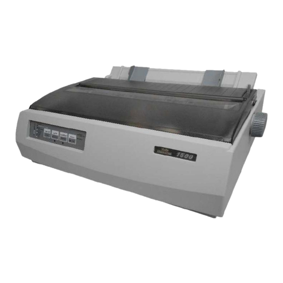
Introduction Congratulations on purchasing the Matrix Printer Tally Dascom 1500. The printer is equipped with a small printhead, which allows printing in draft mode and letter quality. The printer lends itself to a wide range of applications, accepting a variety of data from host computers. -
Page 10: Features
Introduction Features Features Key printer features and options are listed in the next two sections. • Software compatibility. The printer operates with EPSON ESC/P2, IBM Proprinter X(L)24e emulations. For both emulations are OKI superset commands available. • Various character sets. For IBM Mode: IBM Set 1 and Set 2. For EPSON Mode: 15 National Character Sets. -
Page 11: Symbols Used
Introduction Symbols used Important information is highlighted in this manual by three symbols. NOTE: A note is a tip or extra information that may be helpful in installing or using the printer. CAUTION: A caution message provides information that may help you avoid equipment damage, process failure, or inconvenience. -
Page 12: Important Safety Instructions
Introduction Important safety instructions Important safety instructions Read the following instructions thoroughly before starting up your printer in order to pre- vent injuries and avoid damage to the device. • Place the printer on a solid and even base so that it cannot fall down to the ground. •... -
Page 13: Operating The Printer
Operating the printer Overview This chapter explains how to operate the printer. Topics covered are: • Setting up your printer • Getting to know the printer’s major parts and the control panel • Selecting paper • Overview of paper operations •... -
Page 14: Setting Up Your Printer
Setting up your printer Operating the printer Setting up your printer Unpacking the printer Place your packaged printer on a solid base. Make sure that the “Up” symbols point in the correct direction. Open the packaging, lift the printer out of the cardboard box and remove the remaining packaging material. -
Page 15: Placing The Printer
Operating the printer Setting up your printer Placing the printer Place the printer on a solid, flat, surface, ensuring that the printer is positioned in such a way that it can not topple, and that there is easy access to the control panel and paper input devices. -
Page 16: Installation Procedure
Setting up your printer Operating the printer Installation procedure When the printer is first taken out of the Tape packaging box, the cover of the printer is taped as shown in the diagram. Remove the tape. Open the cover of the printer and remove the shipping locks. -
Page 17: Installing The Ribbon Cassette
Operating the printer Setting up your printer Installing the ribbon cassette Proceed as follows to install the ribbon cassette. Only use ribbon cassettes from the manufacturer as products from other manufacturers may damage the printhead or the ribbon drive. Remove the ribbon cassette from its packaging. - Page 18 Setting up your printer Operating the printer Insert the recess on the bottom of the ribbon cassette into the holding pin the mounting. Push the cassette into its mounting until it clicks into position. Close the cover of the printer.
-
Page 19: Connecting The Printer
Operating the printer Setting up your printer Connecting the printer Checking the printer voltage Make sure that the device has been set to the correct voltage (e.g. 120 V in the USA, 230 V in Europe). To do this, check the type plate at the back of the printer. Contact your dealer if the setting is incorrect. -
Page 20: Connecting The Interface Cable
Setting up your printer Operating the printer Connecting the interface cable The printer by default is provided with a parallel Centronics interface and an USB inter- face. For further information about the interfaces, refer to Appendix B, “Interfaces” on page B-1. Make sure that the printer and the com- puter are switched off. -
Page 21: Printer Components
Operating the printer Printer components Printer components This section describes the major parts and controls of the printer and operations of the control panel. Take a moment to become familiar with the printer. Front view Cover Single sheet feeder: to load single sheets. Platen knob: to transport paper if the printer is powered off. -
Page 22: Rear View
Printer components Operating the printer Rear view Paper select lever: to select the paper path USB interface: connect the USB cable here Parallel interface: connect the parallel cable here Tractor: to hold and feed continuous forms Power inlet: Connect the power cord here Space for optional interface 2-10... -
Page 23: Internal View
Operating the printer Printer components Internal view Printhead Paper thickness lever: to adjust the print gap for different paper thicknesses. Ribbon cassette 2-11... -
Page 24: Operations Of The Control Panel
Operations of the Control Panel Operating the printer Operations of the Control Panel This section summarizes status indications and operations of the control panel in Normal mode. For details on Set-Up mode, see Chapter 4, “Special mode” on page 4-1. Tear Off Power / Draft... -
Page 25: Control Panel Keys
Operating the printer Operations of the Control Panel Control panel keys The control panel keys are used for controlling the printer operation. Key functions de- pend on printer status. Tear Off Power / Draft Paper Out Draft Condensed LF/FF Tear Off Online Load/Eject Roman... -
Page 26: Font Selection
Operations of the Control Panel Operating the printer Font selection The printer can print with different fonts. The actual selected font type is displayed by its respective LED light. If you want to change the font setting, press the TEAR OFF / Font key repeatedly until the desired font type is set. -
Page 27: Paper Handling
Operating the printer Paper handling Paper handling Paper types The printer can handle either single sheets or continuous forms. Single sheets, also called cut sheets, include envelopes and non-continuous, multipart forms. Continuous forms in- clude labels and multipart forms fed into the printer using the forms tractors. For best results, use paper that meets the specifications listed in the following table. -
Page 28: Loading Paper
Paper handling Operating the printer Loading paper Your printer can process both fanfold paper and single sheets. For information on the supported paper sizes, please refer to the section “Paper types” on page 2-15 and to Appen- dix A, “Paper specifications” on page A-4. Overview of Paper Operations The following levers are used in paper handling. -
Page 29: Print Gap Lever
Operating the printer Paper handling Print Gap Lever The printer can handle paper with different thicknesses, including multipart forms with up to five parts (original plus four copies). For details on paper thickness specifications, please refer to the section “Paper Specifications” on page 2-15 and to Appendix A, “Paper spec- ifications”... -
Page 30: Fanfold Paper
Paper handling Operating the printer Fanfold paper Move the paper select lever forward to continuous paper position. If necessary, readjust the Print Gap lever for continuous forms (see section “Print Gap Lever” on page 2-17). Slightly press the single sheet feeder to the right or to the left, until the holding pin comes free from its recess. -
Page 31: Unloading Continuous Forms
Operating the printer Paper handling Repeat the procedure for the left tractor and adjust the left forms tractor to accommodate the width of the form. Move the left tractor to make the paper flat. Do not stretch the paper too taut. Push the left locking lever down to secure the tractor in place. -
Page 32: Single Sheets
Paper handling Operating the printer Single sheets Move the paper select lever backward to Single Sheet position. If necessary, readjust the Print Gap lever for continuous forms (see section “Print Gap Lever” on page 2-17). Make sure that the printer is turned on. Raise the single sheet feeder until it locks into its mounting. -
Page 33: Ejecting Single Sheets
Operating the printer Paper handling Ejecting Single Sheets If you print using software which inserts a form feed at the end of each page, each sheet is ejected automatically upon the completion of the page printing. To manually eject sheets of paper: Press the LOAD/EJECT key to execute a forward form feed. -
Page 34: Paper Parking Function
Paper handling Operating the printer Paper Parking Function Switching from fanfold paper to single sheets When using fanfold paper (push tractor), single sheets can be inserted without removing paper from the tractor feeder. The fanfold paper can be moved to the parking position by the switches on the operation panel. -
Page 35: Feeding And Positioning Paper
Operating the printer Paper handling Feeding and Positioning Paper Print Area Definition • Top-of-Form: This value defines the distance between the edge of the paper and the place where you allow the printing to begin (position of line number 1). You can adjust this distance according to the condition of your paper (for example, pre-printed forms). -
Page 36: Continuous Forms
Paper handling Operating the printer Continuous forms (When printed with the top of the dot head) Print Area 6.35 6.35 6.35 ± 0.3 Symbol Dimensions Remark 76.2 ~ 254 Paper width ~ 355.6 (Perforation) Paper length 150 ~ 355.6 (Fold) 6.35 (min) The recommended distance is to be 12mm Or more in actual operation to avoid... -
Page 37: Single Sheets
Operating the printer Paper handling Single sheets Paper Feed Direction Print Area Symbol Dimensions Remark 76.2 ~ 297.2 Paper width 9.6 (min) The distance from the rear end to the printable area 76.2 ~ 558.8 Paper length 6.35 (min) The distance from the front end to the printable area 6.35 (min) The distance from the sides of papers to the... -
Page 38: Setting The First Printing Line (Tof)
Paper handling Operating the printer Setting the first printing line (TOF) You can use the TOF function for setting the vertical position of the first printing line. The mark on the transparent paper pro- tective cover of the printhead can be help- ful if you want to adjust the first printing line. -
Page 39: Selecting Tear-Off Mode
Operating the printer Paper handling Selecting Tear-off mode By default the “Tear” parameter of the printer is set to “Manual”. If you want to transport the paper to tear-off position, you must press the TEAR OFF key. The “Tear” parameter can be set to automatic mode. In this case the paper is transported after a certain duration of time (1, 2, 3, 4 or 5 seconds) automatically to the tear-off posi- tion if the printer does not receive data. - Page 40 Paper handling Operating the printer Press the FF/LOAD/Micro Feed Up/ key to select the parameter group. Press the PARK/PRINT/ six times. You have now reached the TEAR parameter. <FUNCTIONS> PRINTER CONTROL FONT SYMBOL SETS SET UP INTERFACE COMMON (PUSHTRAC) <PAPER SET> <LPI>...
-
Page 41: Paper Types
Operating the printer Paper handling Using the tractor as pull tractor By default the tractor of your printer is mounted at the rear and works as push tractor. You can use the tractor as pull tractor also. Because the paperway is more straight in pull mode this may be useful if you want to print critical paper types. - Page 42 Paper handling Operating the printer Insert the two holding pins of the tractor into the recesses of the mount- ings. Press the two levers into your direc- tion, move the tractor backward until the two pins engage into the recesses of the tractor and release the levers.
-
Page 43: Printing
Printing This chapter describes the following typical printing operations: • Starting, stopping, or resuming printing and viewing last printed lines. • Removing printed pages. The PARK/PRINT, FF/LOAD and the SEL/MENU keys are used for these opera- tions, which are described in this section. For a summary of the operation of these keys, see the section “Operations of the Control Panel”... -
Page 44: Starting Or Stopping Printing
Starting or Stopping Printing Printing Starting or Stopping Printing Starting Printing Before you start to print, make sure that paper is loaded. Also, verify that the paper select lever and the print gap lever are set to the appropriate position. To start printing, make sure that the Ready indicator is lit (the printer is ready). -
Page 45: Special Mode
Special mode Your Printer has two operation modes: • The Normal mode is used for daily operations like paper handling and printing as ex- plained in Chapter 2, “Operating the printer” and Chapter 3, “Printing”. • The Special mode is used to change the printer settings and to test the printer functions. The following table summarizes the purpose of each function. -
Page 46: Set-Up Mode
Set-Up mode Special mode Set-Up mode The Set-Up mode allows you: • To define a printer operating environment for your application software. The printer operating environment includes the emulation, font, symbol sets, horizontal and verti- cal pitches, page length and margins, line mode, and printing direction. It also includes emulation dependent options like the character set. -
Page 47: Entering The Set-Up Mode
Special mode Set-Up mode Entering the Set-Up Mode Proceed as follows to enter the Set-Up mode: Make sure that continous paper is loaded and the printer is in offline mode. Press the SEL/MENU key if necessary. Hold the SHIFT key depressed and press the MENU key. After releasing the keys, the MENU indicator lights up, indicating that the printer has entered the Set-Up mode. -
Page 48: Overview Of The Set-Up Mode
Set-Up mode Special mode Overview of the Set-Up Mode Your Printer has eleven function menus in Set-Up mode. When you press the PARK/PRINT/ key or the TEAR/ key, the following next or previous <FUNCTIONS> menu is printed. PRINTER CONTROL FONT SYMBOL SETS SET-UP INTERFACE... - Page 49 Special mode Set-Up mode To select a function from the <FUNCTIONS> menu: Repeatedly press the PARK/PRINT/ key or the TEAR/ key to position the function you require. Press the FF/LOAD/Micro Feed Up/ key to select the function. The printer prints the first parameter. Repeatedly press the PARK/PRINT/ key or the TEAR/ key to position the option you require.
-
Page 50: Options With Pre-Determined Values
Set-Up mode Special mode Options with Pre-determined Values For some options, you can choose among a limited set of pre-determined values. To se- lect such a value: Repeatedly press the PARK/PRINT/ key or the TEAR/ key to position the value you require. Press the FF/LOAD/Micro Feed Up/ key to select the function. -
Page 51: Options With Undetermined Values
Special mode Set-Up mode Options with Undetermined Values For top and bottom margin parameters, you can choose among a continuous range of values. Example: Changing the Top Margin of the Single Sheet Feeder This example shows how to change the top margin of the single sheet feeder from 0/ 72 inch to 3/72 inch. -
Page 52: Functions, Parameters And Values
Set-Up mode Special mode Functions, parameters and values The following section introduces and explains all the possible menu settings. Please note that some settings are overridden by commands from the computer. Values in bold are the factory settings. PRINTER CONTROL menu Parameter Value Description... -
Page 53: Font Menu
Special mode Set-Up mode FONT menu Parameter Value Description FONT DRAFT, ROMAN, Selects a font to be active when the SANS SERIF, COURIER, power is turned on. For fixed-spaced OCR-B, OCR-A, PRES- fonts, be sure to change the horizontal TIGE, SCRIPT, ORATOR, pitch as well. -
Page 54: Symbol Sets Menu
Set-Up mode Special mode SYMBOL SETS menu Parameter Value Description IBM SET 1/2 IBM SET1 Selects if IBM character set 1 (normal) IBM SET2 or 2 (extended) is active. CODE PAGE CRO-ASCII, Arabic Farsi, Selects the national code page (for the Arabic Urdo, Greek DEC, IBM emulation only). -
Page 55: Set-Up Menu
Special mode Set-Up mode SET-UP menu Parameter Value Description PRINT DIR UNIDIR/UNIDIR(G)/ Unidirectional printing is used for print- BIDIR/SOFT CONTROL ing that needs precise vertical alignment. Unidirectional printing is slower than bi- directional printing. Bi-directional printing: The printer prints in either direction while seeking the next print direction for a shorter print time. -
Page 56: Interface Menu
Set-Up mode Special mode INTERFACE menu Parameter Value Description BUFFER 2KBYTE/16KBYTE/ Selects the size of the interface buffer. 64KBYTE/128KBYTE/ 256KBYTE I/F TYPE PARALLEL/USB/ Selects the type of interface to the com- SERIAL/ETHERNET/ puter. AUTO AUTO: All interfaces are ready for com- munication. -
Page 57: Network Menu
Special mode Set-Up mode Parameter Value Description BUSY LINE DTR/RTS/SSD+/SSD- Selects the signal indicating that the serial interface is in busy state (buffer is full, printer is out of paper or an error is detected). Valid only if the READY/ BUSY protocol has been selected. -
Page 58: Common (Push Trac) Menu
Set-Up mode Special mode COMMON (PUSH TRAC) menu Parameter Value Description PAPER SET COMMON Apply paper properties to all FEED DEPEND paperways or feed dependend. 1LPI/2LPI/3LPI/4LPI/5LPI Sets the line density in lines per /6LPI/8LPI/12LPI inch. 6LPI = 6 lines per inch. TOP MARGIN 0/60INCH/1/60INCH Specifies the position of the top... - Page 59 Special mode Set-Up mode Parameter Value Description TEAR AUTO 1 SEC/AUTO 2 SEC/ Specifies the (auto) start time of AUTO 3 SEC/AUTO 4 SEC/ tear-off feeding. If e.g. AUTO 3 AUTO 5 SEC/MANUAL SEC is selected, auto tear-off feeding is executed 3 seconds after data transmission from the computer has ended.
-
Page 60: Friction Menu
Set-Up mode Special mode FRICTION menu Parameter Value Description 1LPI/2LPI/3LPI/4LPI/5LPI Sets the line density in lines per /6LPI/8LPI/12LPI inch. 6LPI = 6 lines per inch. TOP MARGIN 0/60INCH/1/60INCH Specifies the position of the top line in n/60 inch. See “Print Area /…../119/60INCH/ Definition”... - Page 61 Special mode Set-Up mode Parameter Value Description S-SHEET LD AUTO 1 SEC/AUTO 2 Specifies the (auto) start time of SEC/AUTO 3 SEC/AUTO 4 paper loading. If e.g. AUTO 3 SEC/AUTO 5 SEC/ SEC is selected, auto paper load- MANUAL ing is executed 3 seconds after inserting the paper.
-
Page 62: Recalling Factory Settings (Rcall-Fact)
Set-Up mode Special mode Recalling Factory Settings (RCALL-FACT) Factory settings are those settings pre-selected at the factory. To recall (reset) the factory settings, select the RCALL-FACT function and press the FF/LOAD/Micro Feed Up/ key. After that select the SAVE&EXIT function and press the SEL/MENU/EXIT key. -
Page 63: Using The Diagnostic Functions
Special mode Using the Diagnostic Functions Using the Diagnostic Functions Print Configuration Function This function prints a list of all the printer’s currently selected values. This function is use- ful for checking the printer settings when you first enter the Set-Up mode or just before you exit. - Page 64 Using the Diagnostic Functions Special mode 4-20...
-
Page 65: Printing Test Function
Special mode Using the Diagnostic Functions Printing Test Function The printing test function prints test pages independently of your computer to check printing operations and quality. It does not check the interface between the computer and the printer. The printing test prints all of the characters available in the ASCII character set. To enter the Printing Test mode: a) Make sure that the tractors are loaded with continuous feed paper and that the paper select lever is set forward. -
Page 66: Hex Dump Mode
Using the Diagnostic Functions Special mode Hex Dump Mode The Hex Dump mode prints data and commands in hexadecimal characters and abbrevi- ated control codes. The ASCII characters are used for printing. No characters are printed for hexadecimal codes 80 to FF. The Hex Dump mode is useful for checking whether your computer is sending the correct commands to the printer and whether the printer is executing the commands correctly. -
Page 67: Printing Alignment Adjustment
Special mode Using the Diagnostic Functions Printing Alignment Adjustment This function adjusts the alignment of bi-directional printing. In bi-directional printing, characters that are printed from left to right tend to misalign with characters printed from right to left as shown below: The vertical alignment function corrects the vertical character displacement that some- times occurs with bi-directional printing and results in a poor appearance, especially in printing tables. - Page 68 Using the Diagnostic Functions Special mode Adjust the vertical print alignment at Low Speed: Adjustment of Bi-directional Alignment for Low Speed is performed immediately, after the adjustment value for High Speed is saved. After Paper is loaded, the format of adjustment for Bi-directional Alignment of Low Speed is printed and the paper will au-tomatically advance for viewing after the printing is complete.
-
Page 69: Top Of Form Adjustment Function
Special mode Using the Diagnostic Functions Top of Form Adjustment Function Print positions often change gradually when you use the printer over long periods of time. The ADJUST function allows you to adjust these positions by fine-tuning the Top of Form origin. -
Page 70: Setting Of The First Dot Position On The Left Side
Using the Diagnostic Functions Special mode Setting of The First Dot Position on the Left Side Print positions often change gradually when you use the printer over long periods of time. This adjust function allows you to adjust these positions by fine-tuning the Left Margin origin. - Page 71 Special mode Using the Diagnostic Functions ”xx” is new adjustment value. Exit the setting of the first dot position on the left side mode: Turn the printer off to exit this mode. 4-27...
-
Page 72: Menu Access
Using the Diagnostic Functions Special mode Menu access You can restrict the access to the Set-Up functions to avoid accidentally changing the Set- Up options. To enter Menu Access Function: a) Make sure that the tractors are loaded with continuous feed paper and that the pa- per select lever is set forward. -
Page 73: Setting Setup Mode To Default Value (Standard)
Special mode Using the Diagnostic Functions Setting Setup Mode to Default Value (Standard) This function can initialize the printer to Standard default. To enter setting setup mode to default value (standard): a) Turn the printer off. b) Turn the printer back on while simultaneously pressing the TEAR, PARK and QUIET keys. -
Page 75: Maintenance
Maintenance Your printer requires very little care. Occasional cleaning and replacement of the ribbon cartridge are all that is required (approximately every 6 months or 300 hours of operation, whichever is sooner). Lubrication of the printer is not usually necessary. If the printhead carriage does not move smoothly back and forth, clean the printer in the manner described in this chapter. - Page 76 Cleaning Maintenance Open the cover of the printer and the protective cover of the platen and remove the ribbon cartridge. Using a soft vacuum brush, gently vacuum the platen, the printhead carriage and shaft, and surrounding areas. You can easily slide the printhead to the left or right when the power is off.
-
Page 77: Cleaning The Paper Rollers
Maintenance Cleaning Cleaning the Paper Rollers Clean the platen and paper bail rollers occasionally or when stains or smudges appear on the paper. Use a mild detergent as appropriate. Do not use alcohol to clean the platen or the rollers. Alcohol may cause the rubber to harden. -
Page 78: Replacing The Ribbon Cartridge
Replacing the Ribbon Cartridge Maintenance Replacing the Ribbon Cartridge If printing is too light because of ribbon wear, replace the ribbon cartridge. Appendix E, “Supplies and Options” lists the order number for the ribbon cartridge. The replacement is almost the same as the installation except that it involves removing the old ribbon cartridge and removing the new ribbon cartridge from the carton. -
Page 79: Installing The Ribbon Cartridge
Maintenance Replacing the Ribbon Cartridge Installing the Ribbon Cartridge Proceed as follows to install the ribbon cassette. Only use ribbon cassettes from the manufacturer as products from other manufacturers may damage the printhead or the ribbon drive. Remove the ribbon cassette from its packaging. Open the printer cover. - Page 80 Replacing the Ribbon Cartridge Maintenance Insert the recess on the bottom of the ribbon cassette into the holding pin of the mounting. Push the cassette into its mounting until it clicks into position. When placing the new ribbon cartridge on the carriage, make sure that the thin ribbon does not become bunched or folded at the printhead.
-
Page 81: Replacing The Print Head
Maintenance Replacing the Print Head Replacing the Print Head If a specific dot is not printed for all characters, replace the printhead. The printhead may be hot if you have been printing recently. To remove the printhead: Turn off the printer. Open the cover and and the protective cover of the platen and remove the ribbon car- tridge (see section “Removing the Ribbon Cartridge”... -
Page 83: Troubleshooting
Troubleshooting Your printer is extremely reliable, but occasional problems may occur. You can solve many of these problems yourself, using this chapter. If you encounter problems that you cannot resolve, contact your dealer or service partner for assistance. This chapter is organized as follows: •... -
Page 84: Print Quality Problems And Solutions
Solving problems Troubleshooting Print Quality Problems and Solutions Poor print quality or other printing problems are often caused by incorrect printer set-up or incorrect software settings. A gradual decrease in print quality usually indicates a worn ribbon. The following table identifies common print quality problems and suggests solu- tions. - Page 85 Troubleshooting Solving problems Problem Solution The top margin is wrong. The top margin is the sum of the printer’s top-of- form setting, the software-specified top margin, and the printer’s TOP-MARGIN setting. Proceed as follows: • Make sure that the top-of-form setting is correct. The factory default is 0 mm (0 inch).
-
Page 86: Paper Handling Problems And Solutions
Solving problems Troubleshooting Paper Handling Problems and Solutions The following table describes common paper handling problems and suggests solutions. See the section “Paper handling” in Chapter 2, “Operating the printer” for detailed procedures on loading and using paper. Problem Solution Paper cannot be loaded or fed. -
Page 87: Operating Problems And Solutions
Troubleshooting Solving problems Operating Problems and Solutions The following table identifies common operating problems and suggests solutions. If you cannot resolve a problem, contact your dealer. Problem Solution The power does not turn on. Make sure that the power cord is securely con- nected to both the printer and the battery. -
Page 88: Led States In Error Conditions
Solving problems Troubleshooting LED states in error conditions LEDs light up depending on the following error types. LEDs Status Description Recovery ALARM No paper loaded. Load paper. Other LEDs Normal status ALARM Paper near end. Make sure that Other LEDs Normal status enough paper is loaded. -
Page 89: Printer Failures
Troubleshooting Solving problems Printer Failures A user cannot generally resolve a problem involving defective printer hardware. On de- tecting a fatal error, the printer will: • Stop printing • Turn the Ready (SEL/MENU) indicator off • Blink the ALARM indicator Power off and on again the printer, to recover a fatal error. -
Page 90: Diagnostic Functions
Diagnostic Functions Troubleshooting Diagnostic Functions The printer diagnostic functions are printing test, hex-dump mode and printing alignment adjustment. • PRINTING TEST tells you whether the printer hardware is functioning correctly. If the printer hardware is functional, any problems you are having are probably caused by incorrect printer settings, incorrect software settings, the interface, or the computer. -
Page 91: Chapter A Specifications
Specifications This appendix provides the physical, functional, and performance specifications for your printer. It also contains detailed paper specifications. Printer specifications Item Printing method 24-wire dot matrix impact printer Character pitch 10, 12, 15, 16.6, 17, 20 characters/inch and proportional type (emulation-dependent) Print width 80 characters/line at 10 cpi... - Page 92 Printer specifications Specifications Item Narrow model Wide model Character sets ISO USA, ISO UK, ISO France, ISO Germany, ISO Italy, ISO Swe- den, ISO Norway, ISO Spain, ISO Portugal, Epson USA , Epson France, Epson Germany, Epson UK, Epson Denmark, Epson Swe- den, Epson Italy, Epson Spain, Epson Japan, Epson Norway, Epson Denmark II, Epson Spain II, Epson Latin America, Epson Korea, Epson Legal, CRO-ASCII, Arabic Farsi, Arabic Urdo, Greek DEC,...
-
Page 93: Paper Specifications
Specifications Printer specifications Paper specifications Only use paper that corresponds to the paper specifications and test new sorts of paper before use. Paper type 102–267 mm (4–10.5 in) Continuous Forms Width 102 mm (4 in) up to 559 mm (22 in) Length 1 to 5 No. -
Page 94: Print Area
Paper specifications Specifications Print Area This section illustrates the recommended print area for single sheets and continuous forms. Continuous forms Narrow model: Wc 102 to 267 mm (4 to 10.5 in) Lc 5.08 to 25.4 mm (0.2 to 1 in) -
Page 95: Single Sheets
Specifications Paper specifications Single sheets Narrow model: Ws 102 to 267 mm (4 to 10.5 in) Hs 76 to 364 mm (3 to 14.3 in) Ls 5.08 to 32 mm (0.2 to 1.26 in) - Page 96 Paper specifications Specifications...
-
Page 97: Paper Thickness
Specifications Paper specifications Paper Thickness Paper thickness is given by the weight of the paper in either grams per square meter (g/m ) or in pounds per bond (lbs/bond). The following table shows the allowable paper thickness for one-part paper or for each sheet of multipart paper. The total thickness must not exceed 0.35 mm (0.014 inch). - Page 98 Paper specifications Specifications Five-Part Carbon-Backed 40–64 g/m (11–17 lbs/bond) Middle 40–64 g/m (11–17 lbs/bond) Middle 40–64 g/m (11–17 lbs/bond) Middle 40–64 g/m (11–17 lbs/bond) Bottom 40–81 g/m (11–22 lbs/bond) Two-Part Carbon-Interleaved 40–64 g/m (11–17 lbs/bond) Carbon Counted as one sheet Bottom 40–81 g/m (11–22 lbs/bond)
-
Page 99: Chapter B Interfaces
Interfaces Your printer offers by default the possibility of operating either via a parallel interface or an USB interface. In addition, a serial interface (RS232C) or an Ethernet interface are available as options. Interfaces may vary from unit to unit depending on which configu- ration is purchased. -
Page 100: Parallel Interface Pin Assignment
Parallel interface Interfaces Parallel Interface Pin Assignment Pin No. Signal In/Out Pin No. Parallel In/Out nSTROBE Signal GND DATA0 Signal GND DATA1 Signal GND DATA2 Signal GND DATA3 Signal GND DATA4 Signal GND DATA5 Signal GND DATA6 Signal GND DATA7 Signal GND nACK Signal GND... -
Page 101: Compatible Mode
Interfaces Parallel interface Compatible mode Pin No. Signal name Direction Description nSTROBE Input This signal is a strobe pulse for reading data (Data 0 to 7). The printer reads data when this signal is low. The pulse width must be 1 µs or more at the receiving ter- minal. -
Page 102: Nibble Mode
Parallel interface Interfaces Nibble mode Pin No. Signal name Direction Description PtrClk Output Reverse data transfer phase: This signal (nACK) goes high when data being sent to the host is established. Reverse idle phase: This signal is set low then goes high to interrupt the host, indi- cating that data is available. -
Page 103: Data Transmission Timing
Interfaces Parallel interface Data Transmission Timing In unidirectional mode (conventional Centronics interface), this printer guarantees the re- ceived data when the Data and Data Strobe signals from the computer have the following timing with respect to the Busy and Acknowledge signals from the printer. DATA 0.5 min. -
Page 104: Usb Interface
USB interface Interfaces USB interface The USB (Universal Serial Bus) interface has the following features: • Full compliance with the Universal Serial Bus Specification Revision 2.0 for Full Speed Mode. • USB Function Controller with two FIFO-based Endpoints: – One bidirectional Control Endpoint 0 (8 bytes) –... -
Page 105: Configuration Descriptor
Interfaces USB interface Configuration Descriptor Offset Field Size Value Description bLength Byte 0x09 Size of this descriptor in bytes. bDescriptorType Byte 0x02 Configuration descriptor type. wTotalLength Word 0x0019 No. of bytes in this configura- tion. This includes the configu- ration descriptor plus all of interface and endpoint descrip- tors. -
Page 106: Endpoint 1 Descriptor
USB interface Interfaces Offset Field Size Value Description bInterfaceSubClass Byte 0x01 Subclass code (Printer sub- class). bInterfacePotocol Byte 0x01 Receive. iInterface Byte 0x00 Index of string descriptor describing this interface. Endpoint 1 Descriptor Offset Field Size Value Description bLength Byte 0x07 Size of this descriptor in bytes. -
Page 107: Serial Interface (Option
Interfaces Serial interface (option) Serial interface (option) Your printer’s optional serial interface supports the RS232C specification. The signals are received and transmitted by a 25 pin female connector. Use a serial interface cable that meets the requirements of your host PC. Serial attachment characteristics Signal Description for RS232C Pin No. -
Page 108: Serial Interface Timings
Serial interface (option) Interfaces If user selects RTS as Busy line, this line will be set (Data Terminal Ready) high and will remain high after the serial interface finishes its Reset. If user selects DTR as Busy line, this line will be set high after the serial interface finishes its Reset sequence. - Page 109 Interfaces Serial interface (option) XON/XOFF: INIT Receive Data Valid XOFF XMT Data Receive Data Data received when DSR is low is considered invalid and will be discarded. CTS is required in order for the XON/XOFF protocol to work, because CTS is required in order for data transmission to occur.
-
Page 110: Serial Interface Error Handling
Serial interface (option) Interfaces Serial Interface Error Handling The serial interface recognizes the following errors: • Parity Error • Framing Error • Buffer Overrun Parity Errors: When a parity error is detected, printer will indicate warning status on the lights Printer continues to receive data. -
Page 111: Data Rates
Interfaces Serial interface (option) Data rates The interface supports the following data rates. • 4800 bps • 9600 bps • 19200 bps • 38400 bps Supported protocols This interface will also support the following: • 7 or 8 Data Bits •... - Page 112 Serial interface (option) Interfaces Handshake Handshaking in the serial environment is most commonly handled by software and/or hardware. The manipulation of the hardware handshaking is handled by the following 4 lines: RTS (Request to Send) CTS (Clear to Send) DSR (Data Set Ready) DTR (Data Terminal Ready) Ready/Busy (Hardware Handshake) When Ready/Busy protocol is selected, DTR will be used to pace the data flow from PC.
-
Page 113: Configuring The Serial Interface Of The Pc
Interfaces Serial interface (option) Configuring the serial interface of the PC DOS mode/Command line To use the serial interface of your PC, you must add the following mode commands to the AUTOEXEC.BAT file: mode com1:9600,n,8,1,p mode lpt1:= com1: With the first MODE command, you configure the serial interface Com1 of your PC to the printer’s factory defaults. -
Page 114: Auto Select Interface
Auto Select Interface Interfaces Auto Select Interface The printer can receive data transmitted either a parallel interface or a USB interface as standard. In addition, the printer can receive data transmitted either serial interface or Eth- ernet interface as option. When two different data is sent from different PCs, one by a parallel interface and the oth- er by a USB interface in standard, or one by a parallel interface and the other by a optional serial interface, the data reached the printer is received first and processed first and the... -
Page 115: Chapter C Command Sets
Command Sets This appendix describes printer commands and their parameters. This printer has the following resident command sets (Emulations): EPSON ESC/P2, IBM Proprinter X(L)24e Select the same Emulation on the printer and in your software. -
Page 116: 24 Wire Printer
24 wire printer Command Sets Printer basic functions General USB 2.0 Full Speed IEEE1284 Nibble Mode Emulation IBM Pro printer XL24E EPSON ESC/P2 (T.B.D None Scalable font) Character Set ISO USA, ISO UK, ISO France, ISO Germany, ISO Italy, ISO Sweden, ISO Norway, ISO Spain, ISO Portugal, Epson USA , Epson France, Epson Germany, Epson UK, Epson Denmark, Epson Sweden, Epson Italy, Epson Spain, Epson Japan, Epson... -
Page 117: Emulation
Command Sets 24 wire printer Emulation Command list IBM mode The printer supports the commands shown below. Command sequence Function Horizontal position control Backspace Horizontal tab Carriage return ESC BS 1BH 08H Backspace ESC HT 1BH 09H Horizontal tab ESC CR 1BH 0DH Carriage return ESC D... - Page 118 24 wire printer Command Sets ESC O 1BH 4FH Cancel automatic perforation skip ESC [ \ 1BH 5BH 5CH Set vertical units ESC ] 1BH 5DH Reverse line feed Character attributes Double-wide printing by line Condensed printing Select 10 cpi Cancel double-wide printing by line ESC SO 1BH 0EH...
- Page 119 Command Sets 24 wire printer Command sequence Function Bitimage ESC K 1BH 4BH Normal density bit image graphics ESC L 1BH 4CH Dual density bit image graphics ESC Y 1BH 59H Dual density bit image graphics ESC Z 1BH 5AH High density bit image graphics ESC [ g 1BH 5BH 67H...
-
Page 120: Epson Mode
24 wire printer Command Sets EPSON mode The printer supports the commands shown below. Command sequence Function Horizontal position control Backspace Horizontal Tab Carriage Return ESC $ 1BH 24H Set Absolute Print Position ESC D 1BH 44H Select Horizontal Tabs ESC Q 1BH 51H Set Right Margin... - Page 121 Command Sets 24 wire printer Command sequence Function Character attributes Double-Wide Printing 1 Line Select Condensed Mode Cancel Condensed Mode Cancel Double-Wide Printing 1 Line ESC SO 1BH 0EH Double-Wide Printing 1 Line ESC SI 1BH 0FH Select Condensed Mode ESC ! 1BH 21H Master Select...
- Page 122 Command sequence Function Download and character code setting ESC 7 1BH 37H Enable Upper Control Codes ESC : 1BH 3AH Copy ROM to RAM ESC R 1BH 52H Select an International Character Set ESC t 1BH 74H Select Character Table ESC ( t 1BH 28H 74H Assign Character Table...
- Page 123 Command Sets 24 wire printer Printer unique commands Epson emulation ESC DLE @ P Set multiple print positions 27 16 64 P ESC DLE A m n ... n Select bar code type and size 27 16 65 m n ...
- Page 124 24 wire printer Command Sets IBM emulation ESC DLE @ P Set multiple print positions 27 16 64 P ESC DLE A m n ... n Select bar code type and size 27 16 65 m n ... n ESC DLE B m n [data] Print bar code data 27 16 66 m n [data] ESC DLE C P...
- Page 125 Command Sets 24 wire printer ESC x 0 Select Utility print mode 27 120 48 ESC x 1 Select LQ print mode 27 120 49 ESC { n Change emulation 27 123 n ESC } NUL Software I-Prime 27 125 0 C-11...
-
Page 126: Available Barcode Types
Barcodes Command Sets Barcodes IBM mode Available barcode types CODABAR (NW7) EAN-13 EAN-8 CODE 39 INDUSTRIAL 2 OF 5 INTERLEAVED 2 OF 5 UPC-A UPC-E POST-NET CODE128 Epson mode Available barcode types EAN-13 EAN-8 INDUSTRIAL 2 OF 5 UPC-A UPC-E CODE 39 CODE128 POSTNET... -
Page 127: Chapter D Character Sets
Character Sets This appendix provides character sets available for this printer. Available character sets depend on the emulation selected. They are as follows: • IBM Proprinter X(L)24E emulation: Set 1 and set 2, codepages • Epson-ESC/P(2) emulation: National character sets These character sets include different characters and symbols that are in accordance with the intended languages or usages. -
Page 128: Ibm Proprinter Emulation
IBM Proprinter Emulation Character Sets IBM Proprinter Emulation IBM Set 1 and 2 IBM Set 1 IBM Set 2... -
Page 129: Epson Esc Emulation
Character Sets Epson ESC Emulation Epson ESC Emulation National Character Sets The following fifteen character sets are available: USA, France, Germany, UK, Denmark 1, Sweden, Italy, Spain 1, Japan, Norway, Denmark 2, Spain 2, Latin America, Korea, and Legal. Common Characters The following table shows characters common to the fifteen “national”... -
Page 130: National Characters
Epson ESC Emulation Character Sets National Characters The following table shows “national” characters that differ with languages. Character co- des correspond to NRs in the preceding table. -
Page 131: Restriction Of Fonts
Character Sets Restriction of fonts Non scalable fonts... - Page 132 Restriction of fonts Character Sets...
-
Page 133: Scalable Fonts And Code Pages
Character Sets Restriction of fonts Scalable Fonts and Code Pages SIDM scalable font T.B.D The printer does not support all code pages in the all fonts. See the Code page table and notes. Note1) The Roman typeface is selected on these code pages. Note2) The OCR-A and OCR-B typeface are available on ASCII character set and a part of character of code page 437, 850, 860, 863, 865 and 858. - Page 134 Restriction of fonts Character Sets Script Note 1 Note 1 Note 1 Note 1 Note 1 Orator Note 1 Note 1 Note 1 Note 1 Note 1 Gothic Note 1 Note 1 Note 1 Note 1 Note 1 Souvenir Note 1 Note 1 Note 1 Note 1...
-
Page 135: Supplies And Options
Supplies and Options This appendix lists the accessories and options available for the printer. Contact your deal- er for information on ordering any of these items. The installation of options allows you to expand the capabilities of your printer. Supplies Supply Order Number Black Ribbon Cartridge... -
Page 136: Options
Interface Modules Supplies and Options Interface Modules Interface Order Number Serial interface module, RS-232C, Sub D 25 pin-f connector 043444 Ethernet interface module 10/100 Mb/s 043445... - Page 137 “All rights reserved. Translations, reprinting or copying by any means of this manual complete or in part or in any different form requires our explicit approval. We reserve the right to make changes to this man- ual without notice. All care has been taken to ensure accuracy of information contained in this manual. However, we cannot accept responsibility for any errors or damages resulting from errors or inaccuracies of information herein.”...
- Page 138 Fax: +44 (0) 1256 481400 www.dascom.com www.dascom.com AMERICAS SINGAPORE (ASIA PACIFIC) DASCOM Americas Corporation DASCOM AP Pte Ltd 427 W. Main Street 21 Bukit Batok Crescent Waynesboro, VA 22980 #29-81, WCEGA Tower Singapore 658065 Phone: +1 (877) 434 13 77 Phone: +65 6760 8833 www.dascom.com...
Need help?
Do you have a question about the 1500 and is the answer not in the manual?
Questions and answers