Table of Contents
Advertisement
Quick Links
I n s t r u c t i o n M a n u a l
™
DXLink
Fiber Transmitters and Receivers, Duplex
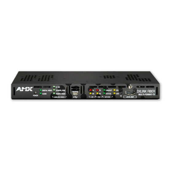
DXLink Multi-Format SMF-D Transmitter
DXLink Multi-Format MMF-D Transmitter
DXLink HDMI SMF-D Receiver
DXLink HDMI MMF-D Receiver
™
D X L i n k
F i b e r T r a n s m i t t e r s / R e c e i v e r s , D u p l e x
R E V A : 0 2 / 2 8 / 1 4
Advertisement
Table of Contents
Troubleshooting

Subscribe to Our Youtube Channel
Related Manuals for AMX DXLink Multi-Format SMF-D


Summary of Contents for AMX DXLink Multi-Format SMF-D
- Page 1 I n s t r u c t i o n M a n u a l ™ DXLink Fiber Transmitters and Receivers, Duplex DXLink Multi-Format SMF-D Transmitter DXLink Multi-Format MMF-D Transmitter DXLink HDMI SMF-D Receiver DXLink HDMI MMF-D Receiver ™...
- Page 2 LIMITED WARRANTY; RETURN, REPAIR AND REPLACEMENT 6.1 AMX warrants the Products to be free of material defects in materials and workmanship under normal use for three (3) years from the Shipping Date (or such other period as may be specified below), subject to the following limitations and exceptions (“Limited Warranty”).
-
Page 3: Table Of Contents
Contents Contents ESD Warning ........................6 Important Safety Information and Instructions ..............7 Information et directives de sécurité importantes..............8 Notices ..........................9 Overview DXLink Fiber, Duplex..................12 Applicability Notice ..........................12 Product Notes............................13 Product Compatibility..........................15 Features – DXLink Fiber Transmitters and Receivers, Duplex..............16 Common Applications.......................... - Page 4 Contents IRL File Transfers ......................61 Overview ..............................61 Preparing for IRL File Transfers in an Endpoint System ................62 Transferring IRL Files ..........................63 NetLinx Programming – DXLink Fiber TXs/RXs ..............66 Overview ..............................66 Device Numbering and Ports........................66 CHANNELs .............................. 68 DXLink Fiber Receiver Video SEND_COMMANDs...................
- Page 5 Contents Appendix C – Virtual NetLinx Master ................110 Overview Virtual NetLinx Master (Masterless)..................110 Setting PC to Static IP Address ......................110 Creating a Virtual Master........................112 Preparing a TX/RX to Work with a Virtual Master ................. 114 Appendix D – Cable Details and Pinout Info..............116 Overview ...............................
-
Page 6: Esd Warning
Anyone performing field maintenance on AMX DXLink Fiber equipment should use an appropriate ESD field service kit complete with at least a dissipative work mat with a ground cord and a UL listed adjustable wrist strap with another ground cord. -
Page 7: Important Safety Information And Instructions
There are no user serviceable parts inside an AMX product; service should only be done by qualified personnel. If you see smoke or smell a strange odor coming from your AMX product, turn it off immediately and call technical support. -
Page 8: Information Et Directives De Sécurité Importantes
Veillez à ce que la prise de courant soit proche de l’appareil et facile d’accès. Veillez à ce que votre appareil AMX soit installé sur une surface stable ou qu’il y soit fermement maintenu. Fermez toutes les composantes de l’équipement avant de relier des pièces, à moins d’indication contraire ... -
Page 9: Notices
No patent liability is assumed with respect to the use of information contained herein. While every precaution has been taken in the preparation of this publication, AMX assumes no responsibility for error or omissions. No liability is assumed for damages resulting from the use of the information contained herein. - Page 10 Notices Apache License, Version 2.0 Contains code Copyright 2006-2013 Giovanni Di Sirio, Licensed under the Apache License, Version 2.0. Apache License Version 2.0, January 2004 http://www.apache.org/licenses/ TERMS AND CONDITIONS FOR USE, REPRODUCTION, AND DISTRIBUTION 1. Definitions. “License” shall mean the terms and conditions for use, reproduction, and distribution as defined by Sections 1 through 9 of this document.
-
Page 11: Warnings And Cautions
Notices pertain to any part of the Derivative Works, in at least one of the following places: within a NOTICE text file distributed as part of the Derivative Works; within the Source form or documentation, if provided along with the Derivative Works; or, within a display generated by the Derivative Works, if and wherever such third-party notices normally appear. -
Page 12: Overview Dxlink Fiber, Duplex
Overview DXLink Fiber, Duplex Applicability Notice The information in this manual applies to the AMX DXLink Fiber Transmitters and Receivers, Duplex listed in the table below. These units handle simultaneous, bidirectional data transfer. They are available in both multimode and single mode models (which differ only in respect to their transceivers which support different cable lengths). -
Page 13: Product Notes
Overview DXLink Fiber, Duplex Product Notes Fiber Optic Transceivers The DXLink Fiber units use SFP+ fiber optic transceivers.* Fiber optic transceivers are self-contained modules that send and receive optical signals over fiber cable. These fiber optic transceivers are either multimode or single mode and must be wired with the corresponding cable type. - Page 14 Overview DXLink Fiber, Duplex Multimode SFP+ Fiber Optic Transceiver A multimode SFP+ fiber optic transceiver is used for the Multi-Format MMF-D TX and the HDMI MMF-D RX. Depending on the transceiver model, it will have a latch that is black or a black label on the latch top with white triangles showing data flow direction.
-
Page 15: Product Compatibility
Overview DXLink Fiber, Duplex Multi-Format MMF-D TX and Multi-Format SMF-D TX The DXLink Fiber Transmitters, Duplex receive an HDMI signal or analog video signal (composite, Y/C, Y/Pb/Pr, RGB, RGBS, or RGBHV) and an audio signal from a source device. The audio can be either digital audio embedded with the HDMI or analog stereo audio. -
Page 16: Features - Dxlink Fiber Transmitters And Receivers, Duplex
DXLink SMF-D units transport video signals over distances up to 6.21 miles (10 km). ® Interruption free content when used in conjunction with a switcher; AMX’s exclusive InstaGate Pro Technology allows audio and video to be switched quickly and easily to every connected display without the difficulties typically associated with HDCP. -
Page 17: Common Applications
Overview DXLink Fiber, Duplex Common Applications DXLink Fiber Transmitters and Receivers, Duplex are ideal for any sources and destinations designed into Enova DGX integrated systems that require the distance capabilities and/or inherent security of fiber with bidirectional data transfer. These transmitters and receivers easily handle campus-wide distribution of sources that are shared between classrooms, in secure military applications, medical facilities, casinos, arenas, museums, and large corporate installations. - Page 18 Serial TX active communication 232 (Serial) RX Yellow Serial RX active communication NetLinx Link/Act Green Active LAN connection to an AMX Network (blinking = #3 Toggle OFF) NetLinx Status Green LAN connection is active CEC is not currently supported Yellow USB is connected and enabled (for details, see page 23) Note: For detailed behavior of the NetLinx Link/Act and Status LEDs on the unit’s front, see page 52.
- Page 19 Overview DXLink Fiber, Duplex Note: When an analog video source cable is plugged into the TX, one of the Analog Video LEDs on the front of the TX and the Video LED on the RX (connected via the switcher) turn green to show the type of video that is present through the system.
-
Page 20: Dxlink Fiber Receivers, Duplex
Overview DXLink Fiber, Duplex Fiber Optic Transceiver The fiber optic transceiver transports digital video, embedded audio, Ethernet, and bidirectional control over fiber optic cable to a DXLink Fiber Input Board, including digitally transcoded analog video signals. The DXLink Fiber path supports HDCP. - Page 21 Serial TX active communication Serial RX Yellow Serial RX active communication NetLinx Link/Act Green Active LAN connection to an AMX Network NetLinx Status Green LAN connection is active CEC is not currently supported Yellow USB is connected and enabled (for details, see page 23) * When the output cable is disconnected from the DXLink Fiber RX or if no EDID can be found on the destination device, the last used Scaling Mode LED will be ON.
- Page 22 Overview DXLink Fiber, Duplex Fiber Optic Transceiver The fiber optic transceiver receives digital video, embedded audio, Ethernet, and bidirectional control over fiber optic cable from a DXLink Fiber Output Board, including digitally transcoded analog video signals. The DXLink Fiber path supports HDCP.
-
Page 23: Common Features/Functionality
Tip: For easiest access to the DIP switch toggles, we recommend setting them before installation. Important: When setting the DIP switch toggles, make sure any toggles that need to be ON are flipped toward the AMX sticker. A four-toggle DIP switch is on the bottom of the DXLink Fiber Transmitters and Receivers. - Page 24 Overview DXLink Fiber, Duplex DXLink Fiber Transmitters, Duplex The USB-mini A/B port labeled “Host” on the rear of the TX connects to a PC (which is the Host). The TX Host port forwards HID (Human Interface Device) keyboard and mouse data received via the switcher from a directed DXLink Receiver’s USB port (the Receiver can be either Fiber or Twisted Pair).
- Page 25 HID Devices A list is available of HID devices which have been tested and found to be working well with the latest firmware (see “DXLink - HID Supported Devices” on the DXLink Fiber Receiver’s product page at www.amx.com). USB LED The USB LED on the front of a Transmitter or Receiver monitors the USB port on the rear of the unit.
-
Page 26: Quick Reference Tables For Modes
Overview DXLink Fiber, Duplex Quick Reference Tables for Modes The DXLink Fiber Transmitters and Receivers, Duplex ship with either a single mode or multimode fiber optic transceiver, which determines the maximum length of the fiber optic cable that can be used (see “Product Notes” on page 13). - Page 27 Overview DXLink Fiber, Duplex Quick Reference Table 2 – Modes for Handling Addressing/Networking (continued) Master Connection Master Connection Mode refers to the modes of communication used for connection to the Mode Master as specified via the SET CONNECTION Telnet command. Auto Mode: •...
-
Page 28: Dxlink Fiber Specifications
• Optical Modulation Amplitude (OMA) sensitivity: -11.1 dBm (typical), Multimode Optical Transceiver -1 dBm (average power) Mean Output Power AMX reserves the right to modify its products and their specifications without notice. Instruction Manual – DXLink™ Fiber Transmitters and Receivers, Duplex... - Page 29 Note: A list of HID devices which have been tested and found to be working well with the latest firmware is available (see “DXLink - HID supported Devices” on the DXLink Fiber Receiver’s product page). AMX reserves the right to modify its products and their specifications without notice. Instruction Manual – DXLink™ Fiber Transmitters and Receivers, Duplex...
- Page 30 Note: Interlaced and progressive video are supported into the Transmitter; progressive is only supported out of the Receiver unless in non-scaling Bypass Mode. AMX reserves the right to modify its products and their specifications without notice. Instruction Manual – DXLink™ Fiber Transmitters and Receivers, Duplex...
- Page 31 Video formats @ 60 Hz frame rate: in Scaling Mode, audio leads video by 12 ms typical (4 ms to 20 ms). In Bypass Mode, audio lags video by 17 ms. AMX reserves the right to modify its products and their specifications without notice. Instruction Manual – DXLink™ Fiber Transmitters and Receivers, Duplex...
- Page 32 * Interlaced video is supported into the Transmitter; progressive is only supported out of the Receiver unless in Scaler Bypass Mode. AMX reserves the right to modify its products and their specifications without notice. Instruction Manual – DXLink™ Fiber Transmitters and Receivers, Duplex...
- Page 33 3.5 mm mini-stereo jack (analog stereo) * Dolby Digital and DTS support up to 48 kHz, 5.1 channels. AMX reserves the right to modify its products and their specifications without notice. Instruction Manual – DXLink™ Fiber Transmitters and Receivers, Duplex...
-
Page 34: Installation And Setup
Installation and Setup Installation and Setup Site Recommendations When placing the DXLink Fiber, Duplex units in an installation, follow the recommendations and precautions in this section to reduce potential setup and operation hazards. Environment Choose a clean, dust free, (preferably) air-conditioned location. ... -
Page 35: Setup Information
Collect all documentation. Note: Please save the original shipping container and packing materials. AMX is not responsible for damage caused by insufficient packing during return shipment to the factory. Shipping boxes are available; for details, contact your AMX representative. - Page 36 Installation and Setup In a system where DXLink Fiber Transmitters and Receivers are used in conjunction with an Enova DGX 8/16/32/64, Example the cable runs from a Transmitter to a DXLink Fiber Input Board and from a DXLink Fiber Output Board to a Receiver Endpoint/ depend on the quality of the cable (see cable specifications on page 28).
- Page 37 Installation and Setup Functions of DXLink Fiber Transmitters and Receivers The diagram in FIG. 10 below shows the functions of DXLink Fiber Transmitters and Receivers. The example descriptions contain the device’s HDCP key count when used in conjunction with DXLink Fiber Boards in an Enova DGX Digital Media Switcher.
- Page 38 Tip: For easiest access to the DIP switch toggles, we recommend setting them before installation. Important: When setting the DIP switch toggles, make sure any toggles that need to be ON are flipped toward the AMX sticker. DIP switch toggles for enabling/disabling special Receiver/Transmitter functionality are located on the bottom of the Receiver and the Transmitters.
- Page 39 Installation and Setup Setting DIP Switch #1 to Enable/Disable Access to ICS LAN 10/100 Port The #1 Toggle is used for enabling/disabling network activity over the physical ICS LAN 10/100 port. It does not affect network activity over the DXLink Fiber connection. (For SEND_COMMANDs used to disable/enable ICS LAN functionality, see page 84.) Tip: Common setup scenarios and their DIP switch settings are provided in a table on page 40.
- Page 40 The DXLink Fiber Transmitters and Receivers, Duplex are classified as V Style modules, which have optional V Style mounting hardware. These versatile mounting options include rack trays and mounting brackets for desktops, under desks, on walls, and on poles. For details on V Style Mounting Kit options, see www.amx.com. V Style Single Module Pole Mount...
- Page 41 Installation and Setup Fiber Optic Cable Requirements Warning: DXLink Fiber units use laser transceivers, which are Class 1 Eye Safe per IEC 60825-1/CDRH requirements. While the Class 1 category indicates that the invisible laser used is safe, we recommend avoiding direct eye exposure when using any optical fiber products (see the OSHA directive on page 13). Fiber Optic Cable Requirements Fiber optic cable with LC termination for snap coupling with SFP+ transceivers ...
- Page 42 Installation and Setup ICS LAN 10/100 Connector LEDs ICS LAN 10/100 LEDs The following information applies to the LEDs on the ICS LAN 10/100 (RJ-45) connector on the units. Green LED Yellow LED LEDs on unit FIG. 16 ICS LAN 10/100 connector LEDs Link/Activity (L/A) Green LED: ...
-
Page 43: Dxlink Fiber Tx - Attaching Signal, Transport, And Control Cables
Installation and Setup DXLink Fiber TX – Attaching Signal, Transport, and Control Cables Important: Before attaching cables, be sure to set the DIP switch’s toggles if necessary (see page 40). Warning: DXLink Fiber units use laser transceivers, which are Class 1 Eye Safe per IEC 60825-1/CDRH requirements. -
Page 44: Dxlink Fiber Tx - Applying Power
Serial TX active communication 232 (Serial) RX Yellow Serial RX active communication NetLinx Link/Act Green Active LAN connection to an AMX Network NetLinx Status Green LAN connection is active CEC is not currently supported Yellow USB port connection is established... -
Page 45: Dxlink Fiber Rx - Attaching Signal, Transport, And Control Cables
Installation and Setup DXLink Fiber Transmitters, Duplex – LED Troubleshooting If indicator LEDs for units do not respond with a normal display as stated in table on the previous page: Check all power connections. Check the “Detailed NetLinx (Link/Act and Status) LED Behavior” section on page 52. ... -
Page 46: Dxlink Fiber Rx - Applying Power
Serial TX Serial TX active communication Serial RX Yellow Serial RX active communication NetLinx Link/Act Green Active LAN connection to an AMX Network NetLinx Status Green LAN connection is active CEC is not currently supported Yellow USB port connection is established * When the HDMI output cable is disconnected from the DXLink Fiber RX or if no EDID is found on the destination device, the Auto LED is ON. -
Page 47: Serial Data Transfer And Ir Flow Control
Endpoint Mode with an Enova Digital Media Switcher. The switcher has an integrated NetLinx Central Control Processor which provides native AMX control at each remote location fed by a DXLink Fiber Transmitter / Receiver. Control is sent over fiber optic cable (via the fiber optic transceivers). -
Page 48: Optional: Dxlink Fiber Tx/Rx - Ir Control
Installation and Setup Serial Control – Endpoint Mode and SEND_COMMANDs With DXLink Fiber TX/RX Duplex units connected to a switcher (in Endpoint Mode), serial operations are handled by the host providing control of the endpoints. The Master’s programming specifies where the serial commands are sent (this is handled independently from the routing of the video signals). -
Page 49: Optional Accessories For Usb Transport
Installation and Setup Optional Accessories for USB Transport CC-USB, USB Programming Cable (FG10-5965) Order this optional programming cable for connecting to a PC (for use with DXLink Fiber Transmitters only). CC-MINIUSB, Mini USB to PC Cable Adapter (FG5967-20) Order this optional cable adapter for connecting a keyboard/mouse device to the DXLink Receiver (for use with DXLink Fiber Receivers only). -
Page 50: Dxlink Fiber Rx Scaling Button And Scaling Modes
Auto Mode (default) – allows the destination device to automatically scale the signal to its preferred or native ® resolution (this mode is AMX’s SmartScale Technology in action). Manual Mode – allows the user to configure the resolution that the video will display through a destination ... - Page 51 Installation and Setup Persistence of Scaling Mode The Scaling Mode has two levels of persistence – the basic level happens automatically and can be considered temporary; the advanced level is the result of sending the PERSISTAV command to the DXLink Fiber Output Board and is permanent (unless the Scaling Mode is changed and the PERSISTAV command is sent again).
-
Page 52: Detailed Netlinx (Link/Act And Status) Led Behavior
Installation and Setup Detailed NetLinx (Link/Act and Status) LED Behavior The tables below provide detailed descriptions of all blink patterns for the NetLinx Link/Act and Status LEDs on the front of the Transmitter and Receiver units. Note: The term “light show” refers to the back-and-forth scanning pattern of the LEDs associated with the LEDs on the DXLink Transmitter and Receiver. -
Page 53: Dxlink Fiber Tx - Local Out (Hdmi) Port
When connecting switching systems via fiber optic transceivers, AMX recommends no more than three switcher throughputs (see the “Example” on the next page). -
Page 54: Network Configuration
Network Configuration Network Configuration Overview DXLink Fiber Transmitters and Receivers support two IP Addressing Modes: Static IP and DHCP (with link-local fallback*). To avoid having a large system consume numerous IP addresses, the Transmitters and Receivers default to disabling the network connection functionality. - Page 55 NetLinx Studio. Note: NDP is a device discovery method used by NetLinx Masters. With NDP Beacon enabled, the Master will transmit NDP Beacons for AMX’s proprietary device discovery. Telnet IP Configuration Commands The SET IP and GET IP Telnet commands listed in the tables in Appendix B (which start on page 93) can be sent directly to the DXLink Fiber units via a Telnet terminal session.
-
Page 56: Factory Default Parameters
192.168.1.1 DNS2 (for static mode) 192.168.1.1 DNS3 (for static mode) 192.168.1.1 DNS Domain amx.com Hostname Last 7 digits of the serial number Master Connection Mode NDP - for details, see page 108 Master URL (for TCP and UDP URL “” (blank) -
Page 57: Device Ids
Network Configuration Device IDs Device IDs Model ID (16-bits) Bound* DXLF-MFTX-SM-D 0x0195 DXLF-HDMIRX-SM-D 0x0194 DXLF-MFTX-MM-D 0x0195 DXLF-HDMIRX-MM-D 0x0194 * The Device ID for unbound units defaults to 0x014B until the unit is bound and the system is refreshed in NetLinx Studio. - Page 58 The device must first be placed in ID Mode in NetLinx Studio or the momentary press will be ignored. Note: The latest version of NetLinx Studio is available to download and install from www.amx.com. Refer to the NetLinx Studio Online Help for instructions on using the application.
- Page 59 Network Configuration Tip: In the following two procedures – if you start a press and hold sequence with the ID Pushbutton and then decide not to change the settings, before you release the ID Pushbutton remove power from the unit to abort the procedure.
- Page 60 Network Configuration Once all actions in Step 3 are completed, the LEDs all turn off, indicating the Transmitter or Receiver is ready to reboot. The Transmitter or Receiver automatically reboots to complete the process. Tip: To monitor the ID Pushbutton boot state of a unit, see the “ID Pushbutton Boot and NetLinx LED Behavior”...
-
Page 61: Irl File Transfers
IRL File Transfers IRL File Transfers Overview The NetLinx Studio software application (available for free download from www.amx.com) provides the ability to transfer IR Library files to NetLinx devices such as DXLink Fiber Transmitters and Receivers. Endpoint System (with a Switcher) When a Transmitter and/or a Receiver are being used in conjunction with a switcher as an endpoint system, the switcher’s integrated Master is used for the IRL file transfer. -
Page 62: Preparing For Irl File Transfers In An Endpoint System
Go to www.amx.com and login as a Dealer to download the latest version. Download the applicable IRL file from www.amx.com (Partners / Search Devices) to your PC. Verify the following: Verify that an Ethernet/RJ-45 cable is connected from the switcher’s integrated Master to the network (e.g., from the LAN 100/1000 port on an Enova DGX 32 to a LAN). -
Page 63: Transferring Irl Files
IRL File Transfers Transferring IRL Files The File Transfer tool in NetLinx Studio is used to map IRL files to DXLink Fiber Transmitters and Receivers. The instructions below assume that the preparations on the previous page for IRL file transfers for an endpoint system have been completed. - Page 64 IRL File Transfers Select the type of file (in this case, IRL/IRV Files) that you want to add to the File list for transfer. Click Add. A standard Open dialog box opens with the Files of type selection set to IR Code files (*.IRL/*.IRV). Locate and select the IRL file that you want to add.
- Page 65 Additional Documentation For additional information on using NetLinx Studio, refer to the Instruction Manual – NetLinx Studio v3.3 and the WebConsole & Programming Guide – NetLinx Integrated Controllers (available at www.amx.com). Additional IRL Information Unlike NetLinx NI-Controllers, ICSLan powered devices (such as the DXLink Fiber Transmitter and Receiver units) are not capable of having their IRL files received via the File Transfer dialog box, nor do they support the LOADIRL SEND_COMMAND.
-
Page 66: Netlinx Programming - Dxlink Fiber Txs/Rxs
NetLinx Programming – DXLink Fiber TXs/RXs NetLinx Programming – DXLink Fiber TXs/RXs Overview Important: Before DXLink Fiber TXs and RXs can receive any NetLinx SEND_COMMANDs, the DIP switch’s #3 Toggle must be set to ON or the devices will not be accessible from a NetLinx control system. The DXLink Fiber Transmitters and Receivers recognize a select number of SEND_COMMANDs and CHANNELs. - Page 67 Note: For additional information on using NetLinx Studio, refer to the “Instruction Manual – NetLinx Studio v3.3” and the “WebConsole & Programming Guide – NetLinx Integrated Controllers” (available at www.amx.com). Note: All command text is based on a Unicode index.
-
Page 68: Channels
NetLinx Programming – DXLink Fiber TXs/RXs CHANNELs Channel Function This channel On indicates that the DXLink Fiber unit has a valid UTP (twisted pair cable) connection to a switcher with an integrated Master. If the channel is Off, the DXLink Fiber unit is incorrectly connected. 1-253 Key presses from selected remote control. - Page 69 NetLinx Programming – DXLink Fiber TXs/RXs Video SEND_COMMANDs (Receivers), continued ?VIDOUT_RES Syntax: Requests the resolution and SEND_COMMAND <DEV>,"'?VIDOUT_RES'" Valid responses: refresh rate of the video through the Receiver. • horizontal = An integer value representing the horizontal. • vertical = An integer value representing the vertical. May have an additional qualifier Note: If the Scaling Mode is such as “p”...
-
Page 70: Dxlink Fiber Receiver Audio Send_Commands
NetLinx Programming – DXLink Fiber TXs/RXs Aspect Ratio Conversion Policy Options Note: The commands for setting/verifying the aspect ratio conversion policy are on the previous page. Stretch (to fit) – This aspect ratio conversion policy option (default) scales the video to full screen size in both horizontal and vertical directions regardless of the input aspect ratio. -
Page 71: Dxlink Fiber Transmitter Video Send_Commands
NetLinx Programming – DXLink Fiber TXs/RXs DXLink Fiber Transmitter Video SEND_COMMANDs DXLink Fiber Transmitter Video SEND_COMMANDs are sent to Port 7 unless otherwise noted. Note: Asynchronous notifications are available for the Transmitters via NetLinx Studio (and Telnet). Note: All text is based on a Unicode index. Video SEND_COMMANDs (Transmitters) Command Description... - Page 72 NetLinx Programming – DXLink Fiber TXs/RXs Video SEND_COMMANDs (Transmitters), continued ?VIDIN_STATUS Important: Send to Port 7 for digital video and Port 8 for analog video. Syntax: Requests the status of the video input on the Transmitter. SEND_COMMAND <DEV>,"'?VIDIN_STATUS'" Valid responses: status = NO SIGNAL, UNKNOWN SIGNAL, VALID SIGNAL Example: SEND_COMMAND dvTX,"'?VIDIN_STATUS'"...
- Page 73 NetLinx Programming – DXLink Fiber TXs/RXs Video SEND_COMMANDs (Transmitters), continued ?VIDIN_RES_REF Important: Send to Port 7 for digital video and Port 8 for analog video. Syntax: Requests the resolution and refresh rate of the video through the SEND_COMMAND <DEV>,"'?VIDIN_RES_REF'" Valid responses: Transmitter.
- Page 74 NetLinx Programming – DXLink Fiber TXs/RXs Video SEND_COMMANDs (Transmitters), continued ?VIDIN_HDCP Important: Send to Port 7. Syntax: Requests the video HDCP compliance SEND_COMMAND <DEV>,"'?VIDIN_HDCP'" setting of the video input port Example: addressed by the D:P:S. SEND_COMMAND VIDEO_INPUT_1,"'?VIDIN_HDCP'" Returns a COMMAND of the form: VIDIN_STATUS-<ENABLE|DISABLE>...
-
Page 75: Dxlink Fiber Transmitter Audio Send_Commands
NetLinx Programming – DXLink Fiber TXs/RXs Video SEND_COMMANDs (Transmitters), continued VIDIN_HSHIFT Important: Send to Port 8. Syntax: Sets the horizontal shift value of the analog video input port addressed by SEND_COMMAND <DEV>,"'VIDIN_HSHIFT-<value>'" the D:P:S. Valid responses: value = -50. . .50 Examples: SEND_COMMAND "'VIDIN_HSHIFT-2'"... -
Page 76: Ir Send_Commands
NetLinx Programming – DXLink Fiber TXs/RXs Audio SEND_COMMANDs (Transmitters), continued AUDIN_FOR AUDIN_FORMAT Syntax: Selects the audio input source that will SEND_COMMAND <DEV>,"'AUDIN_FORMAT-<format>'" Valid responses: be embedded on the HDMI signal through the Transmitter. format = HDMI, SPDIF, ANALOG Note: When the Transmitter is set to Example: route digital video (input 7), you can SEND_COMMAND dvTX,"'AUDIN_FORMAT-ANALOG'"... - Page 77 NetLinx Programming – DXLink Fiber TXs/RXs IR SEND_COMMANDs (Transmitters and Receivers), continued CH SEND_COMMAND • All channels below 100 are transmitted as two digits. • If the IR code for ENTER (function #21) is loaded, an Enter will follow the Send IR pulses for the selected number.
- Page 78 NetLinx Programming – DXLink Fiber TXs/RXs IR SEND_COMMANDs (Transmitters and Receivers), continued GET BAUD The port sends the parameters to the device that requested the information. Syntax: Get the IR port’s current communication parameters. SEND_COMMAND <DEV>,"'GET BAUD'" Example: SEND_COMMAND dvRXRS232,"'GET BAUD'" The port responds with: Port <port #>,<baud>,<parity>,<data>,<stop>...
- Page 79 NetLinx Programming – DXLink Fiber TXs/RXs IR SEND_COMMANDs (Transmitters and Receivers), continued You can use the 'CTON' to set pulse lengths and the 'CTOF' to set time Off between pulses. Generate a single IR pulse. Syntax: SEND_COMMAND <DEV>,"'SP',<code>" Valid responses: code = IR code value 1 to 252 (253 to 255 reserved).
-
Page 80: Serial Send_Commands
NetLinx Programming – DXLink Fiber TXs/RXs Serial SEND_COMMANDs On the DXLink Fiber units, SERIAL SEND_COMMANDs are sent to Port 1. Serial SEND_COMMANDs (Transmitters and Receivers) Command Description B9MOFF This command works in conjunction with the 'B9MON' command. • Disables 9-bit in 232 mode. Set the port’s communication parameters for stop and data bits •... - Page 81 NetLinx Programming – DXLink Fiber TXs/RXs Serial SEND_COMMANDs (Transmitters and Receivers), continued RXCLR Syntax: Clear all characters in the receive SEND_COMMAND <DEV>,"'RXCLR'" Example: buffer waiting to be sent to the Master. SEND_COMMAND dvRXRS232,"'RXCLR'" Clears all characters in the receive buffer waiting to be sent to the Master. RXOFF Syntax: Disable the transmission of incoming...
-
Page 82: Dxlink Fiber Transmitter Usb Send_Commands
NetLinx Programming – DXLink Fiber TXs/RXs DXLink Fiber Transmitter USB SEND_COMMANDs On the DXLink Transmitter, USB SEND_COMMANDs are sent to Port 5. USB SEND-COMMANDs (Transmitter) Command Description ?USB_HID_SERVICE Syntax: Requests the status for SEND_COMMAND <DEV>,"'?USB_HID_SERVICE'" the USB HID pass Example: through setting (Enable or SEND_COMMAND dvTX,"'?USB_HID_SERVICE'"... -
Page 83: Common Dxlink Fiber Tx/ Rx Send_Commands
NetLinx Programming – DXLink Fiber TXs/RXs Common DXLink Fiber TX/ RX SEND_COMMANDs Common NetLinx SEND_COMMANDs for the DXLink Fiber Transmitters and Receivers are provided in the following table. These commands can be sent to any valid port (Port 1 through Port 8); the #3 Toggle must be set to ON. Common NetLinx SEND-COMMANDs (Transmitters and Receivers) Command Description... -
Page 84: Dxlink Fiber System Send_Commands
NetLinx Programming – DXLink Fiber TXs/RXs DXLink Fiber System SEND_COMMANDs DXLink Fiber System SEND_COMMANDs can be sent to any valid port (Port 1 through Port 8) on the Transmitters or Receivers. DXLink Fiber System SEND_COMMANDs (Transmitters and Receivers) Command Description ICSLAN Syntax: disable/enable ICS LAN... -
Page 85: Send_String Escape Sequences
NetLinx Programming – DXLink Fiber TXs/RXs SEND_STRING Escape Sequences The DXLink Fiber units support several special SEND_STRING escape sequences. If any of the character combinations listed below are found anywhere within a SEND_STRING program instruction, they will be treated as a command and not the literal characters. -
Page 86: Troubleshooting
Troubleshooting Troubleshooting Overview The troubleshooting suggestions/strategies provided apply to the DXLink Fiber Transmitters and Receivers unless otherwise noted. Five potential types of issues are covered in this chapter: Basic troubleshooting Determining HDCP compliance Power DXLink Fiber Network setup ... -
Page 87: Dxlink Fiber Troubleshooting
Troubleshooting DXLink Fiber Troubleshooting Signal concerns – If you are experiencing general signal problems, it may be because of fiber cable quality issues. Be sure to check the “Fiber Optic Cable Requirements” section on page 41. Audio – If you are experiencing audio problems, it may be because you are trying to pass Dolby, DTS, or high ... -
Page 88: Technical Support
If this manual has not satisfactorily answered your questions regarding the DXLink Fiber Transmitters and Receivers or they are not operating as expected, please contact your AMX representative or technical support. Have the serial numbers for the units and the system’s switcher ready. We recommend recording the serial numbers in an easily accessible location. -
Page 89: Appendix A - Upgrading The Firmware
Appendix A – Upgrading the Firmware Overview The NetLinx Studio software application (available for free download from www.amx.com) provides the ability to transfer KIT files to NetLinx devices such as DXLink Fiber Transmitters and Receivers. The firmware on the Transmitters and Receiver can be upgraded in the field. -
Page 90: Preparing For Kit File Transfers In An Endpoint System
Go to www.amx.com and login as a Dealer to download the latest version. Download the latest Firmware (KIT) file from www.amx.com on the DXLink Fiber Transmitter or Receiver product page to your PC. (Place KIT files on a local drive for speedy throughput.) Verify the following: Verify that an Ethernet/RJ-45 cable is connected from the switcher’s integrated Master to the network... -
Page 91: Transferring Kit Files
Appendix A – Upgrading the Firmware Transferring KIT Files The system will be non-operational during the upgrade procedure below. The Firmware Transfers tool in NetLinx Studio is used to map KIT files to DXLink Fiber Transmitters and Receivers. The instructions below assume that the preparations on the previous page for an endpoint system have been completed. To send a KIT file to a DXLink Fiber Transmitter or Receiver: In NetLinx Studio from the Tools menu, select “Firmware Transfers >... -
Page 92: Firmware Versions
Appendix A – Upgrading the Firmware Firmware Versions The following table contains firmware version information for the DXLink Fiber units. DXLink Fiber Firmware Versions Applies to Version # Date Differences Multi-Format MMF-D TX 1.0.3 2/27/14 Baseline Multi-Format SMF-D TX HDMI MMF-D RX 1.0.1 2/27/14 Baseline... -
Page 93: Appendix B - Telnet (Terminal) Commands
Welcome Banner with and without security enabled (Receiver shown): Without Telnet security enabled, a session will begin with a welcome banner similar to the following: Welcome to DXLF-HDMIRX v0.9.12 Copyright AMX LLC 2014 > If Telnet security is enabled, user credentials are required: ... -
Page 94: Telnet Username And Password
Appendix B – Telnet (Terminal) Commands To establish a terminal connection via NetLinx Studio: In the Online Tree, select the DXLink Fiber unit and right-click to access the shortcut menu. Select Launch Telnet Window via NetLinx Studio. The Telnet window opens and the Welcome Banner appears (Receiver shown). At the prompt (>), type the Telnet command and press Enter. -
Page 95: Telnet Commands
Appendix B – Telnet (Terminal) Commands Setting a Telnet Username and Password To set a Telnet username and password: Establish a terminal connection via Telnet (see page 93). Type Set Telnet Username, and press Enter. The program will prompt you to enter a new Telnet username; enter a username and press Enter. The program will indicate that the username is being stored. - Page 96 Appendix B – Telnet (Terminal) Commands Telnet Commands (continued) audio Note: This command applies only to the Receiver. Shows audio signal status. Note: This command must be entered in lower Example: case only. >audio -------------------------------- Audio Output ============ Analog Audio HDMI Audio Audio Mute Audio Input...
- Page 97 Note: Devices other than the DXLink Fiber device itself will be ignored. Example: >device status 32002:1:0 Device Status ------------- Device 32002 AMX LLC, DXLF-MFTX, 0.0.105.0 contains 8 Ports Port 1 - Channels:255 Levels:8 MaxStringLen=64 Types=8 bit MaxCommandLen=64 Types=8 bit The following input channels are on:None The following output channels are on:None...
- Page 98 Lease Renew (T1): SAT 01/11/2031 00:59:02 (129600 sec) Lease Rebind (T2): SUN 01/12/2031 03:59:02 (226800 sec) DNS Servers -------------------------------- Domain suffix: amx.internal Entry 1: 192.168.40.7 Entry 2: 192.168.40.8 Note: The system number and IP addressing information displayed is reflective of actual operating values, not stored parameters.
- Page 99 Gets the list of DNS entries. Example: >get dns DNS Servers ------------------------------- Domain suffix: amx.internal Entry 1: 192.168.40.7 Entry 2: 192.168.40.8 Note: When the DXLink Fiber unit is in DHCP Mode, these are active values, NOT the stored values that only apply to Static IP Mode.
- Page 100 Appendix B – Telnet (Terminal) Commands Telnet Commands (continued) GET USB Note: This command applies only to the Transmitter. Displays USB statistics. Example: >get usb USB Statistics : Number of USB Connections Number of Keyboard Messages Number of Mouse Messages Number of Table Messages Number of Connections Number of Disconnects...
- Page 101 Appendix B – Telnet (Terminal) Commands Telnet Commands (continued) scaler Note: This command applies only to the Receiver. Shows video scaler status. Note: This command must be entered in lower Example: case only. >scaler -------------------------------- Scaler Input Width 1920 Height 1200 VFreq ZoomW...
- Page 102 • Maximum length = 25 characters. If the name entered exceeds 25 characters, it will be truncated. • The value is stored in non-volatile memory. • If no value specified, an automatic name consisting of AMX, the product name, and serial number will be used. Note: This command requires a reboot to enable new settings.
- Page 103 Appendix B – Telnet (Terminal) Commands Telnet Commands (continued) SET IP Sets the IP configuration of a specified device. Enter a Host Name, Type (DHCP or Fixed), IP Address, Subnet Mask, and Gateway IP Address. Note: DHCP implies “DHCP with link-local fallback”. Note: For NetLinx Masters, the Host Name can only consist of alphanumeric characters.
- Page 104 Appendix B – Telnet (Terminal) Commands Telnet Commands (continued) SET TELNET Note: This command is supported but is not presently in the Help file list of commands. PASSWORD Sets the username for a secure Telnet session. • Default = blank (no password required) •...
- Page 105 Color Space: RGB 444 Video is not encrypted. SHOW DNS Shows the DNS settings. Example: >show dns DNS Servers ------------------------------------------ Domain suffix: amx.internal Entry 1: 192.168.40.7 Entry 2: 192.168.40.8 SHOW LOG Displays the message log. Syntax: SHOW LOG <start> • Use <start> to specify the message number to start displaying.
- Page 106 Appendix B – Telnet (Terminal) Commands Telnet Commands (continued) SHOW TCP Shows the TCP list. Example: >show tcp Show TCP List ------------- The following TCP connections exist(ed): 1: 192.168.43.57:23 <=> 192.168.43.51:51418 (connected) 2: Port:24 (listening) 3: Port:23 (listening) 4: Port:7 (listening) SHOW UDP Shows the UDP list.
- Page 107 Appendix B – Telnet (Terminal) Commands Telnet Commands (continued) video Note: This command applies only to the Receiver. Shows video signal status. Note: This command must be entered in lower Example: case only. >video -------------------------------- Input Video Signal ================== Input Video ----------- Video Signal Valid...
-
Page 108: Master Connection Modes
Appendix B – Telnet (Terminal) Commands Telnet Commands (continued) Note: This command applies only to the Receiver. Displays information about the XG fiber link status control. Note: This command must be entered in lower Usage: case only. xg info Shows XG block information xg stats Shows XG block statistics xg stats on 5000... -
Page 109: Notes On Specific Telnet Clients
UDP – Protocol does not have a built-in retry mechanism, but consumes fewer resources on the Master. AMX’s UDP implementation of NetLinx employs a retry mechanism to provide the reliability of TCP with the resource efficiency of UDP. URL vs. NDP vs. Auto Determining which connection method to use for Master Connection Mode is essentially a matter of deciding what information the device should use to identify the correct Master to connect to. -
Page 110: Appendix C - Virtual Netlinx Master
Appendix C – Virtual NetLinx Master Appendix C – Virtual NetLinx Master Overview Virtual NetLinx Master (Masterless) A Virtual NetLinx Master can be created using your PC, which allows NetLinx Studio to facilitate direct file transfers to a DXLink Fiber Transmitter or Receiver when a Master is not available. Four basic procedures must be completed for Virtual Master file transfers: Set the PC to a static IP address (below). - Page 111 Appendix C – Virtual NetLinx Master Note: The following procedure was completed on Windows 7 Professional (other versions may vary slightly). To set a PC to Static IP Mode: From the Start menu on the desktop taskbar, select Control Panel / Network and Sharing Center. Click “Change adapter settings”...
-
Page 112: Creating A Virtual Master
Appendix C – Virtual NetLinx Master Press the Tab key on your keyboard to auto-fill the Subnet mask field. Click OK and click Close. Important: When finished using the PC as a Virtual Master, change the setting in the dialog box shown in Step 4 back to “Obtain an IP address automatically.”... - Page 113 Appendix C – Virtual NetLinx Master Under Transport Connection Option, select Virtual NetLinx Master. Select Virtual NetLinx Master Under Virtual NetLinx Master Options: Optional – Change the Master System Number (default = 1; range = 1 to 65535). Select the desired IP Address in the Available Connections list (this will be the static IP address that the PC was set to in the previous instructions).
-
Page 114: Preparing A Tx/Rx To Work With A Virtual Master
Appendix C – Virtual NetLinx Master Preparing a TX/RX to Work with a Virtual Master Preparing the DXLink Fiber Transmitter or Receiver to work with a Virtual Master requires placing the unit in Static IP Mode, assigning it a device ID, and setting the connection type to TCP. Note: When using the first set of instructions below, only one DXLink Fiber TX/RX can be connected to the Virtual Master at a time because the static IP address is the same for all DXLink Fiber units. - Page 115 Appendix C – Virtual NetLinx Master At the prompt (>), type SET DEVICE <num> and press Enter. For the <num> value, the valid range of device numbers is 0 to 31999. Setting a device number does not require a reboot to take effect. ...
-
Page 116: Appendix D - Cable Details And Pinout Info
Important: System configurations will vary, necessitating different cable requirements for each system. Cables not available through AMX should come from a trusted cable supplier. Note: When cabling video through either the HDMI port or HD-15 port, installers should be aware of how cabling will affect audio signals. -
Page 117: Hd-15 Connector Cable Pinout
Appendix D – Cable Details and Pinout Info HD-15 Connector Cable Pinout HD-15 connectors are found on the DXLink Fiber Transmitters. These connectors are used to accept a variety of analog video signals from a source device. The following table provides cable pinout details for HD-15 connections for VGA, VGA-RGBS, VGA-RGsB, component, S-Video, and composite. -
Page 118: Dvi Pinout For Dvi-To-Hdmi Cable
Appendix D – Cable Details and Pinout Info DVI Pinout for DVI-to-HDMI Cable The pinout in FIG. 29 is for the DVI receptacle for a DVI-to-HDMI cable which can be used with the DXLink Fiber unit when a DVI-D source signal is required DVI Cable Connector Pinout DVI Input Pin # Signal Name... -
Page 119: Appendix E - Supported Input Resolutions
Appendix E – Supported Input Resolutions Appendix E – Supported Input Resolutions Available Pixel Display and Refresh Rate The available pixel display and refresh rates for the input devices connected to the DXLink Fiber Transmitters are listed in this appendix. The resolutions in the following tables are supported on the DXLink Fiber Transmitters and can be set using a SEND_COMMAND. - Page 120 Appendix E – Supported Input Resolutions DVI, HDMI, and VGA Supported Input Resolutions (continued) Resolution Horizontal Vertical Refresh HDMI Comments Video Standard Name Active Active (Hz) and DVI Support Pixels Pixels Support 1280x720@60 1280 VESA DMT 1280x720p@60 1280 720p...
- Page 121 Appendix E – Supported Input Resolutions Composite and S-Video Supported Input Resolutions Composite and S-Video Supported Input Resolutions Resolution Name Horizontal Vertical Refresh Comments Video Standard Active Pixels Active Pixels (Hz) 720x480i@60 480i 720x576i@50 576i Component Video Supported Input Resolutions Component Video Supported Input Resolutions Resolution Name Horizontal Active...
-
Page 122: Appendix F - Supported Output Resolutions
Appendix F – Supported Output Resolutions Appendix F – Supported Output Resolutions HDMI and DVI Supported Output Resolutions The resolutions in the following table are supported on the DXLink Fiber RX and can be set using a SEND_COMMAND. The horizontal/vertical/refresh information from the Resolution Name (in the first column) can be entered in a SEND_COMMAND command (VIDOUT_RES_REF) to specify scaling parameters for the DXLink Fiber RX. -
Page 123: Digital Video Output Resolution Support
Appendix F – Supported Output Resolutions Digital Video Output Resolution Support Important: The resolutions and timings in the lists in this section can only be set using DGX Configuration Software via the Enova DGX Switcher when the DXLink Receiver is being used directly from a DXLink Fiber Output Board. - Page 124 Appendix F – Supported Output Resolutions CVR (RGB Color Space): 768x480p@60Hz 800x600p@60Hz 800x600p@120Hz 848x480p@60Hz 960x600p@60Hz 1024x576p@60Hz 1024x640p@60Hz 1024x768p@60Hz 1024x768p@120Hz 1064x600p@60Hz 1152x720p@60Hz 1152x864p@60Hz 1224x768p@60Hz 1280x720p@60Hz 1280x768p@60Hz 1280x768p@120Hz 1280x800p@120Hz 1280x960p@60Hz 1280x1024p@60Hz 1360x768p@60Hz 1360x768p@120Hz 1400x1050p@60Hz 1440x900p@60Hz 1536x960p@60Hz 1600x1000p@60Hz 1600x1200p@60Hz 1680x1050p@60Hz 1704x960p@60Hz 1728x1080p@60Hz 1800x1350p@60Hz 1864x1050p@60Hz 1920x1080p@60Hz 1920x1200p@60Hz...
- Page 125 Appendix F – Supported Output Resolutions CVT (RGB Color Space): 640x360p@85Hz 1280x720p@50Hz 640x400p@75Hz 1280x720p@60Hz 640x400p@85Hz 1280x720p@75Hz 640x480p@75Hz 1280x720p@85Hz 640x480p@85Hz 1280x768p@50Hz 768x480p@60Hz 1280x768p@60Hz 768x480p@75Hz 1280x768p@75Hz 768x480p@85Hz 1280x768p@85Hz 800x600p@50Hz 1280x800p@50Hz 800x600p@60Hz 1280x800p@75Hz 800x600p@75Hz 1280x800p@85Hz 800x600p@85Hz 1280x960p@50Hz 848x480p@50Hz 1280x960p@60Hz 848x480p@60Hz 1280x960p@75Hz 848x480p@75Hz 1280x960p@85Hz 848x480p@85Hz 1280x1024p@50Hz 960x600p@50Hz...
- Page 126 Appendix F – Supported Output Resolutions DMR (RGB Color Space): 1280x800p@60Hz 1366x768p@60Hz 1600x900p@60Hz DMT (RGB Color Space): 640x350p@85Hz 640x400p@85Hz 640x480p@60Hz 640x480p@72Hz 640x480p@75Hz 640x480p@85Hz 720x400p@85Hz 800x600p@56Hz 800x600p@60Hz 800x600p@72Hz 800x600p@75Hz 800x600p@85Hz 848x480p@60Hz 1024x768i@43Hz 1024x768p@60Hz 1024x768p@70Hz 1024x768p@75Hz 1024x768p@85Hz 1152x864p@70Hz 1152x864p@75Hz 1152x864p@85Hz 1280x800p@60Hz 1280x960p@60Hz, 280x960p@75Hz 1280x960p@85Hz 1280x1024i@43Hz...
-
Page 127: Appendix G - Fiber Transceiver Replacement
Appendix G – Fiber Transceiver Replacement Appendix G – Fiber Transceiver Replacement Applicability Notice This appendix pertains to replacement of SFP+ fiber optic transceivers for the DXLink Fiber Transmitters and Receivers listed in the table on page 12. Latch and/or label color Dust plug FIG. -
Page 128: Replacing An Sfp+ Fiber Optic Transceiver
Appendix G – Fiber Transceiver Replacement Replacing an SFP+ Fiber Optic Transceiver Tips for Fiber Tips for Fiber Optic Connections: Optic Keep dust plugs in transceivers until you are ready to make a connection. Connections Clean fiber optic cable ends before attaching to transceivers (be sure to follow the cable manufacturer’s instructions for inspecting and cleaning the cable ends). - Page 129 Appendix G – Fiber Transceiver Replacement Restore the removed transceiver’s latch to an upright position and replace the dust plug that originally shipped with the transceiver. Place the transceiver in an ESD shielded bag and set aside. Tip: Leave the dust plug in the replacement transceiver for Step 5 to reduce possibility of damaging the transceiver / socket.
-
Page 130: Appendix H - Edid Management/Programming
Many EDIDs can be stored on the DXLink Transmitter and the DXLink Fiber Input board for each input – HD-15 (analog) and HDMI (digital). The AMX DXLink supported EDIDs are classified as follows: ALL RESOLUTIONS (default for both analog and digital inputs) ... - Page 131 An AMX EDID Library is available at www.amx.com (search for EDID Library). This library provides EDID files that can be used with AMX products. A report is provided for each EDID file, which describes the EDID features in detail, in order to assist you in selecting the most appropriate EDID for your system needs.
-
Page 132: Dgx Configuration Software Overview
EDID requirements for HDMI or VGA. AMX’s DGX Configuration Software has a tabbed view for EDID Programming. This view can be used to re-program the EDID EEPROM chips for the HD-15 and HDMI connectors on the DXLink Fiber Transmitters, allowing for custom configuration of the EDID data that is stored on them. -
Page 133: Dxlink Fiber Connection To Pc
Appendix H – EDID Management/Programming DXLink Fiber Connection to PC To use DGX Configuration Software with a DXLink Fiber Transmitter: Attach one end of a USB mini-B cable to the Program port on the front of the DXLink Fiber Transmitter. Attach the open end of the USB mini-B cable to the PC where the DGX Configuration Software was installed. -
Page 134: Edid Programmer View
AMX VGA or HDMI EDID set. The AMX VGA EDID set and the AMX HDMI EDID set each consist of a number of common EDID settings (for VGA and HDMI timing details, see page 119). In most cases, the DXLink Fiber Transmitter can be used as is from the factory with no adjustments. - Page 135 Appendix H – EDID Management/Programming Reading and Saving EDID Data from a DXLink Fiber Transmitter’s Input Connector When DGX Configuration Software discovers and displays “Inputs” for an DXLink Fiber Transmitter, the input is numbered twice to allow for reading from either a VGA (HD-15) or an HDMI source device. The DGX Configuration Software reads the EDID data from the USER EDID 1 EEPROM location, regardless of the VIDIN_EDID setting.
- Page 136 HDMI or HD-15 input connector on a DXLink Fiber Transmitter. User defined EDIDs are currently available from technical support. An “AMX Library” of EDID files will be available on at www.amx.com in conjunction with a future firmware release.
- Page 137 - Schedules and registration for any AMX University course - Travel and hotel information - Your individual certification requirements and progress 3000 RESEARCH DRIVE, RICHARDSON, TX 75082 USA • 800.222.0193 • 469.624.8000 • 469-624-7153 fax • 800.932.6993 technical support • www.amx.com...
Need help?
Do you have a question about the DXLink Multi-Format SMF-D and is the answer not in the manual?
Questions and answers