Table of Contents
Advertisement
Quick Links
Advertisement
Table of Contents

Related Manuals for AMX TXC4 Series


Summary of Contents for AMX TXC4 Series
- Page 1 TXC Wireless Transmitters Instruction Manual t a k e c o n t r o l...
- Page 2 AMX is not liable for any damages caused by its products or for the failure of its products to perform, including any lost profits, lost savings, incidental damages, or consequential damages. AMX is not liable for any claim made by a third party or made by you for a third party.
-
Page 3: Table Of Contents
IR, RF, Radio Code, and IR Frequency Settings ....5 Overview IR, RF, and IR Frequency Settings Radio Code Setting radio codes Trigger switch operation (TXC4 series only) Radiation hazards Specifications............... 13 Overview Troubleshooting Guidelines..........17 Overview Technical Support ..............19... - Page 4 Table of Contents TXC Wireless Transmitters...
-
Page 5: Introduction
The TXC4, TXC32+, and TXC16+ line of hand-held wireless transmitters control a wide variety of devices, using infrared (IR) or radio frequency (RF) transmission medium, connected to an AMX AXCESS Control System. They can transmit IR signals at 38 kHz or 455 kHz and RF signals at 303.875 MHz. - Page 6 Pushbutton 48 Each pushbutton performs a specific operation according to the AXCESS software program in your AMX Control System. The red transmission LED, located in the top-center of the transmitter, flashes when you press one of the pushbuttons, indicating that an RF or IR signal is being transmitted.
-
Page 7: Features
Features The TXC transmitters offer these features: • RF and IR wireless control • Selectable 38 kHz or 455 kHz IR frequency • Custom pushbutton configurations • Microprocessor-based architecture • Custom-engraved overlay and pushbutton layouts • Alternate radio frequencies • LED to indicate signal transmission (TXC16+ and TXC32+ only) •... - Page 8 Introduction TXC Wireless Transmitters...
-
Page 9: Ir, Rf, And Ir Frequency Settings
IR, RF, Radio Code, and IR Frequency Settings Overview The TXC series transmitters transmit IR or RF signals, depending on how you set positions 1, 2, and 3 on the 10-position DIP switch (Figure 4) located under the battery cover. You must set the DIP switch position 3 to ON for RF mode. IR, RF, and IR Frequency Settings Figure 4 shows the DIP switch settings for IR and RF modes. -
Page 10: Radio Code
Radio Code Each pushbutton on your transmitter represents an AXCESS channel number. All of Note the pushbuttons on a transmitter represents a group of channel numbers. This Do not set both DIP switch grouping is known as a radio code. After the radio code is set on the transmitter, positions 1 and 2 to the ON each button you press sends a specific channel number to the control system. - Page 11 TXC4 Radio codes, DIP switch settings, and transmission ranges (con’t) Channel code transmission ranges Radio DIP switch positions TXC4 code From 10.5 11.5 12.5 13.5 14.5 15.5 TXC Wireless Transmitters IR, RF, Radio Code, and IR Frequency Settings...
- Page 12 - 1) + (radio code number multiplied by 16). The formula to determine the channel number of a TXC4 series transmitter is (radio code offset) + (radio code number multiplied by 16). Refer to Figure 9 for the TXC4 series radio code offsets.
- Page 13 Figure 9 TXC4 series radio code offsets Pushbutton Radio code offset Radio code offset shift TXC4 series radio code offsets 2 & 3 1 & 4 Pushbutton 1 Pushbutton 2 Pushbutton 4 Pushbutton 3 Trigger TXC Wireless Transmitters IR, RF, Radio Code, and IR Frequency Settings...
-
Page 14: Trigger Switch Operation (Txc4 Series Only)
Trigger switch operation (TXC4 series only) The TXC4 series transmitters have a trigger switch on the front underside of the unit. On the TXC4L and TXC4L+ models, this switch operates the laser pointer. On the TXC4 and TXC4+ models, this switch can be configured in one of two ways: Configuration 1 (default): Pushbutton 1 Remove the battery cover and locate position 4 (Figure 6) of the DIP switch. -
Page 15: Radiation Hazards
Radiation hazards Laser beams produce light frequencies that are harmful to the human eye. DO NOT look into, or shine a laser beam into another person's eyes. The frequencies of laser light can cause eye retina damage. Read the following WARNING . Warning Laser radiation hazard DIRECT EYE EXPOSURE... - Page 16 IR, RF, Radio Code, and IR Frequency Settings TXC Wireless Transmitters...
-
Page 17: Specifications
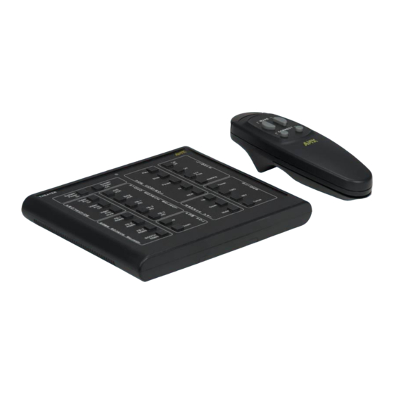
Specifications Overview The TXC4 series (Figure 10) specifications are listed in Figure 11. The TXC16+ (Figure 12) specifications are listed in Figure 13, and the TXC32+ (Figure 14) specifications are listed in Figure 15. Figure 10 TXC4 transmitter Figure 11... - Page 18 Figure 12 TXC16+ transmitter TXC16+ specifications Figure 13 TXC16+ specifications Dimensions (HWD) 5.2” x 2.8” x 0.75” (13.34 cm x 7.11 cm x 1.91 cm) Weight 4 oz (113.4 g) with batteries Enclosure Black injection-molded plastic Power Two N-size, 1.5-volt alkaline batteries (supplied) Pushbuttons Up to 16 black, gray, and/or white •...
- Page 19 Figure 14 TXC32+ transmitter Figure 15 TXC32+ specifications Dimensions (HWD) 5.2” x 6.2” x 0.75” (13.34 cm x 15.88 cm x 1.91 cm) TXC32+ specifications Weight 9 ounces (255 grams) with batteries Enclosure Black injection-molded plastic Power Four N-size, 1.5-volt alkaline batteries (supplied) Pushbuttons Up to 48 black, gray, and/or white •...
- Page 20 Specifications TXC Wireless Transmitters...
-
Page 21: Troubleshooting Guidelines
Read through the following information (Figure 16) if you are experiencing a problem with your TXC16+ or TXC32+transmitter. If the problem cannot be resolved, call your AMX dealer. Refer to the Technical Support section of this manual. Troubleshooting the TXC Wireless Transmitters... - Page 22 Troubleshooting Guidelines TXC Wireless Transmitters...
-
Page 23: Technical Support
Technical Support Overview Prior to calling AMX for assistance, check your AXlink, power, and cable connections, and the integrity of your software operating system. Reload the software to see if something in the program is causing the problem. If the problem is not resolved, reload the program from a new copy of your master disk. - Page 24 11995 Forestgate Drive Document No. 034-004-1295 2/98 © 1998 AMX Corporation Dallas, Texas 75243 AMX reserves the right to alter specifications without notice at any time. AMX and 800/222-0193 972/644-3048 the AMX logo are registered trademarks of AMX Corporation. All other trademarks Fax 972/907-2053 www.amx.com...
Need help?
Do you have a question about the TXC4 Series and is the answer not in the manual?
Questions and answers