Advertisement
Quick Links
Overview
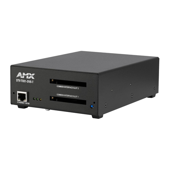
The DTV-TX01-DVB-T Transmitter is one component of an AMX TDS Television Delivery
System. The AMX TDS system delivers digital TV and video signals across a privately
provided IP network infrastructure. The DTV-TX01-DVB-T Transmitter (FG1410-01) supports
DVB-T (terrestrial) signals, and features RF 1/2 OUT output connectors to allow multiple
streams for maximum channel coverage (FIG. 1).
Common Interface Slots 1 & 2
NETWORK
RJ45 connector
(to network)
Streaming status (green)
Network Connectivity status (green)
RF OUT 2
RF IN 2
RF IN 1
RF OUT 1
FIG. 1
DTV-TX01-DVB-T Transmitter
Product Specifications
DTV-TX01-DVB-T Transmitter
Dimensions (HWD):
2.18" x 5.41" x 7.60" (5.56cm x13.74cm x 19.30cm)
Weight:
2.75 lbs (1.25 kg)
Power Requirements:
• Power Consumption: 6W
• Voltage rating: nominal 12 to 13.5V DC
• Current draw at 12V: 0.5A
Tuners:
2 internal tuners
RF Input Level:
• 480 ˜ 860 MHz
• -35 ˜ -50 dBm
Front Panel Components
• NETWORK
Standard RJ45 connector.
Connector:
• LEDs:
Three LEDs indicate the status of the Transmitter:
• Streaming LED (green)
• Network Connectivity LED (green)
• Power status LED (yellow)
• Common Interface
Dual Common Interface Slots enable the Transmitter to select encrypted
Slots 1 & 2:
channels in cases where this is supported by the broadcaster.
Note: Before de-scrambling content using the Common Interface Slots,
ensure that you have the appropriate authority/rights to transmit the
de-scrambled content on your network.
• RESET button:
Press to reboot the Transmitter.
Rear Panel Components:
• RF INPUTs:
Two TV aerial plug/Belling-Lee connectors accept incoming terrestrial
signals.
• RF OUTPUTs:
Two RF aerial plug/Belling-Lee connectors allow you to daisy chain
DTV-TX01-DVB Transmitters together.
Note: There is a 3db signal loss on RF output relative to the RF input.
• Factory Reset
The recessed Factory Reset button on the rear panel allows you to
Button:
perform a full factory reset (resets flash and reboots the Transmitter in
DHCP mode):
• Press and hold the recessed Factory Reset button while simultaneously
pressing the Reset button on the front panel.
• Continue to hold the Factory Reset button while the unit is rebooting.
• Release when the Streaming Status LED begins to flash.
• SERIAL (RS232):
DB9 serial connector for local command line interface (RS232 only).
• PWR:
2-pin mini-phoenix connector provides 12VDC power from the power
supply.
Note: A 12VDC Power Supply is required (not included)
DTV-TX01-DVB-T
Power status (yellow)
Factory
RS232 Serial connector
Reset
(DB9: for local device
button
control only)
Digital Video Broadcasting, Terrestrial, dual tuner transmitter
DTV-TX01-DVB-T Transmitter (Cont.)
Environment:
• Operating Temperature: 32°F - 122°F (0°C to 50°C)
• Operating Humidity: Max. relative humidity - 85% (non-condensing)
Certifications:
• CE
• FCC part 15 Class A
Other AMX
• DTV-MA01 TDS Management Appliance (FG1412-01)
Equipment:
• DTV-RX01-SD Receiver (FG1411-01)
(front)
• DTV-TX02-DVB-S Transmitter (FG1410-02)
• DTV-RK, Rack Mount Kit for DVB-T/S Transmitters (FG1410-60)
• CC-232 Serial Communication Cable (FG10-752-04)
• 12V Power Supply
AMX TDS System Description
The AMX TDS system can be deployed in any installation where digital A/V broadcast over
Reset
IP is desired, and delivers Digital TV and other encoded A/V signals to a number of TV sets,
button
or desktop PC's.
System Components
The AMX TDS system consists of several components, including a DTV-MA01 TDS
Management Appliance, Receiver (and IR Remote Controller), and Transmitter modules.
There are two Transmitter units available, to accommodate Terrestrial and Satellite digital TV
broadcasts. See the AMX TDS Operation/Reference Guide for details.
(rear)
Network Considerations
Because of the high bandwidth associated with A/V distribution, the TDS system is typically
managed via a separate IT infrastructure. However, content may be streamed over the main
2-pin
network if desired. Consult your IT representative to determine the proper network
PWR
configuration for the TDS system.
connector
The AMX TDS system transmits audio/video using IP multicast. In order for this to work
satisfactorily, it is vital that the network switches are multicast-enabled in order to prevent
unwanted flooding of traffic on the network.
•
Within the context of AMX TDS documentation. the term "Multicast-enabled" means
that all network switches carry out IGMP snooping, and one switch must function as
the IGMP querier.
•
AMX Digital TV supports version 2 of IGMP.
Front Panel Components
ETHERNET 10/100 Port
The ETHERNET 10/100 (RJ45) port on the front panel provides 10/100 BaseT network
connectivity.
Network Port Pinouts and Signals
The following table lists the pinouts, signals, and pairing for the NETWORK port.
RJ45 Network Port Pinouts and Signals
Pin
Signals
1
TX +
2
TX -
3
RX +
4
no connection
5
no connection
6
RX -
7
no connection
8
no connection
Consult the Network Administrator for correct cabling from the DTV-TX Transmitter onto the
network. For remote connectivity, the Firewall may have to be configured to open port 2008
for remote connectivity over UDP. Ports 5000 and 5001 are required for the Transmitters as
well as any ports used for the TDS Multicast stream.Ports 5002 and 5003 are fixed as the
multicast stream output ports.
Ethernet LEDs
L/A - Link/Activity LED
lights (green) when the
Ethernet cables are
connected and terminated
correctly.
FIG. 2
Ethernet LEDs
Status LEDs
There are three LEDs on the front panel to indicate various types of device status:
•
Power Status (yellow): Lights to indicate that the Transmitter is receiving power and is
functional. If the LED fails to light, check your 12VDC Power connection.
•
Network Connectivity Status (green): Lights to indicate that the Transmitter is
connected to the network.
•
Streaming Status (yellow): Flashes if only one tuner is streaming. Steady on if both
tuners are streaming.
Default IP Address
By default, DTV Transmitters are set to DHCP. See the Setting the Transmitter's IP Address
via the CONSOLE Port section (below).
Installation Guide
Connections
Pairing
1 --------- 1
1 --------- 2
2 --------- 2
3 --------- 3
3 --------- 6
4 --------- 4
5 --------- 5
6 --------- 6
7 --------- 7
8 --------- 8
SPD - Speed LED
lights (yellow) when the
connection speed is 100 Mbps
and turns Off when speed is
10 Mbps.
Color
Orange-White
Orange
Green-White
Blue
Blue-White
Green
Brown-White
Brown
Advertisement

Related Manuals for AMX DTV-TX01-DVB-T


Summary of Contents for AMX DTV-TX01-DVB-T
-
Page 1: System Components
AMX TDS System Description (to network) The AMX TDS system can be deployed in any installation where digital A/V broadcast over Reset IP is desired, and delivers Digital TV and other encoded A/V signals to a number of TV sets, button or desktop PC's. -
Page 2: Reset Button
©2013 AMX. All rights reserved. AMX and the AMX logo are registered trademarks of AMX. AMX reserves the right to alter specifications without notice at any time. 3000 RESEARCH DRIVE, RICHARDSON, TX 75082 • 800.222.0193 • fax 469.624.7153 • technical support 800.932.6993 • www.amx.com...
Need help?
Do you have a question about the DTV-TX01-DVB-T and is the answer not in the manual?
Questions and answers