Avaya C360 Installation And Configuration Manual
Converged stackable switches
Hide thumbs
Also See for C360:
- User manual (286 pages) ,
- Installation and configuration manual (248 pages) ,
- Quick start for hardware installation (36 pages)

Related Manuals for Avaya C360


Summary of Contents for Avaya C360
- Page 1 Installation and Configuration for the Avaya C360 Converged Stackable Switches Software Version 4.5 10-601564 Issue 1 July 2006...
- Page 2 © 2006 Avaya Inc. All Rights Reserved. Notice While reasonable efforts were made to ensure that the information in this document was complete and accurate at the time of printing, Avaya Inc. can assume no liability for any errors. Changes and corrections to the information in this document may be incorporated in future releases.
-
Page 3: Table Of Contents
C360 Front Panels ........C360 Rear Panel ........ - Page 4 Establishing a Console Connection ......Assigning C360 IP Stack Address ......
- Page 5 Configuring the Switch ....... . C360 Default Settings .......
- Page 6 IEEE 802.1x Implementation in the C360 ..... Configuring the C360 for 802.1x ......
- Page 7 LAG CLI Commands ....... . LAG Implementation in the C360 ......
- Page 8 LLDP Agent CLI Commands ......Chapter 9: Avaya C360 Layer 3 Features ....151 Obtaining and Activating a License Key .
- Page 9 Power over Ethernet CLI Commands..... . . Chapter 11: C360 Device Manager ..... 193 Overview .
- Page 10 Overview ........Implementation of Stack Health in the C360 ....
- Page 11 Appendix C: Standards and Compatibility....221 Avaya C360 Standards Supported ......
- Page 12 Contents 12 Installation and Configuration Guide Avaya C360 Multilayer Stackable Switches, version 4.5...
-
Page 13: Before You Install The Avaya C360
Touching the circuit boards unless instructed to do so may damage them. PRECAUCIÓN: El switch C360 y sus módulos de ampliación contienen componentes sensibles a PRECAUCION: descargas electrostáticas. Tocar las tarjetas sin autorización del personal técnico puede dañarlas. -
Page 14: Conventions Used In The Documentation
Lists of parameters from which you should choose are enclosed in square brackets [ ] and ● separated by a vertical bar |. If you enter an alphanumeric string of two words or more, enclose the string in “quotation ● marks”. 14 Installation and Configuration Guide Avaya C360 Multilayer Stackable Switches, version 4.5... -
Page 15: Notes, Cautions, And Warnings
Conventions Used in the Documentation Notes, Cautions, and Warnings CAUTION: You should take care. You could do something that may damage equipment or CAUTION: result in loss of data. PRECAUCIÓN: Debe tener cuidado. Usted podría hacer algo que puede dañar el equipo o PRECAUCION: resultar en pérdida de datos. - Page 16 Before you Install the Avaya C360 16 Installation and Configuration Guide Avaya C360 Multilayer Stackable Switches, version 4.5...
-
Page 17: Section 1: Avaya C360 Overview
Section 1: Avaya C360 Overview Issue 1 July 2006... - Page 18 18 Installation and Configuration Guide Avaya C360 Multilayer Stackable Switches, version 4.5...
-
Page 19: Chapter 1: Avaya C360 Overview
Chapter 1: Avaya C360 Overview The C360 is a line of converged stackable switches that provide high availability, quality of service (QoS), and IEEE 802.3af Power over Ethernet (PoE) to enhance converged network infrastructure operations. With a range of PoE and non-PoE configurations, the C360 series is a powerful, yet cost-effective option for enterprise applications. -
Page 20: Network Optimization
- Up to five simultaneous Telnet connections for multiple CLI (Command Line Interface)-based sessions over the network. Refer to Establishing a Telnet Connection on page 65 for further information. 20 Installation and Configuration Guide Avaya C360 Multilayer Stackable Switches, version 4.5... -
Page 21: Redundancy
C360 Features and Benefits - Up to two simultaneous encrypted SSH (Secure Shell) connections for multiple CLI-based sessions over the network. Refer to Establishing an SSH Connection page 66 for further information. - SNMP (Simple Network Management Protocol) "get" and "set" requests (support for SNMPv1, SNMPv2 and SNMPv3). -
Page 22: Vlan Support
Avaya C360 Overview Stack redundancy - in the unlikely event that a C360 switch or Octaplane link should fail, ● stack integrity is maintained if the redundant cable is connected to the stack. The broken link is bypassed and data transmission continues uninterrupted. -
Page 23: Quality Of Service (Qos)
C360 Features and Benefits Remote Authentication Dial-In User Service (RADIUS) provides flexible administrative ● control over authentication and authorization processes. Refer to RADIUS on page 80 for further information. SNMP v3 adds security features to the SNMP v1 and SNMP v2c feature set. Refer to ●... -
Page 24: Power Over Ethernet (Poe) Support On C360-Pwr Switches
Protocol) Configuration on page 164 for further information. - Open Shortest Path First (OSPF). Refer to OSPF (Open Shortest Path First) Configuration on page 167 for further information. 24 Installation and Configuration Guide Avaya C360 Multilayer Stackable Switches, version 4.5... -
Page 25: Management
175 for further information. Management The C360 switch is designed for plug-and-play operation: you need to configure only basic IP information for the switch and connect it to the other devices in your network. If you have specific network needs, you can configure and monitor the switch - individually or as part of a stack - through its various management interfaces. -
Page 26: C360 Switch Configurations
C360 Switch Configurations Table 2 summarizes the C360 switch configurations Table 2: C360 Switch Configurations Model 10/100BASE-T GBIC SFP Ports Ports (on 10/100BASE-T ports) C363T C363T-PWR C364T C346T-NEBS C364T-PWR 26 Installation and Configuration Guide Avaya C360 Multilayer Stackable Switches, version 4.5... -
Page 27: Section 2: Installing The C360
Section 2: Installing the C360 Issue 1 July 2006... - Page 28 28 Installation and Configuration Guide Avaya C360 Multilayer Stackable Switches, version 4.5...
-
Page 29: Chapter 2: Avaya C360 Front And Rear Panels
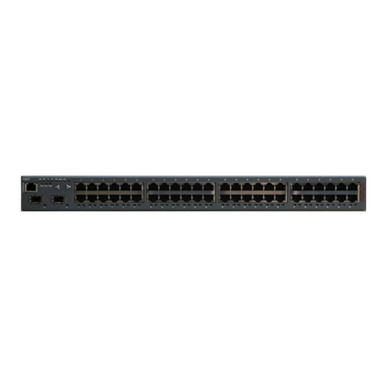
Chapter 2: Avaya C360 Front and Rear Panels This chapter describes the front and rear panels of the C360 switches, including the LEDs, buttons and power inlets: C360 Front Panels ● C360 Rear Panel ● C360 Front Panels The front panel contains LEDs, controls, and connectors. The status LEDs and control buttons provide at-a-glance information. - Page 30 Figure 4: C364T-PWR Front Panel Figure 5: C360 Function LEDs Figure notes: 1. PoE LED on C360-PWR only 2. Left front panel button 3. Right front panel button 30 Installation and Configuration Guide Avaya C360 Multilayer Stackable Switches, version 4.5...
- Page 31 Left Right Button Button Hspd Figure notes: 1. PoE LED on C360-PWR only Table 3: C360 Function LED Descriptions 1 of 3 Description LED Status Name Power Status OFF - Power is off ON - Power is on Blinking - Main power is down and BUPS is...
- Page 32 10 Mbps 100 Mbps 1000 Mbps Link OFF - No LAG defined for this port Aggregation ON - Port belongs to a LAG Group (Trunking) 2 of 3 32 Installation and Configuration Guide Avaya C360 Multilayer Stackable Switches, version 4.5...
-
Page 33: C360 Rear Panel
LEDs on the stack remain lit until the procedure is complete. C360 Rear Panel The C360 rear panel contains a stacking module slot, AC power input and BUPS DC input. Note: The C/S: and SW versions on your C360 switches may differ from those shown in... - Page 34 Avaya C360 Front and Rear Panels Figure 7: C360 Rear Panel Figure notes: 1. AC Input 2. BUPS DC Input 3. X360STK slot (shown covered) 34 Installation and Configuration Guide Avaya C360 Multilayer Stackable Switches, version 4.5...
-
Page 35: Chapter 3: Installation
Chapter 3: Installation The C360 switch is ready to work after you complete the installation instructions described in this chapter. After you have completed the procedures in this chapter, proceed to Chapter 4: Powering Up the Avaya C360 The following steps are described in this chapter: Preparing Needed Tools ●... -
Page 36: Site Preparation
Installation Site Preparation You can mount the C360 alone or in a stack in a standard 19-inch equipment rack located in a wiring closet or equipment room. You can build a logical stack of up to ten C360 switches. Ensure that the location where you install your Replace variable w/ short product name fulfills... -
Page 37: Rack Mounting (Optional)
(C364T NEBS only) Rack Mounting (Optional) The C360 chassis fits in most standard 19-inch racks. It is 1U (44.45 mm, 1.75”) high. You can mount the Avaya C360 in a standard 19" rack either in “front-mount” or “mid-mount” positions using the brackets supplied with the chassis. -
Page 38: Before You Install The C360 In A Rack
2. Mid-mount position 3. Front mount position Before you Install the C360 in a Rack When installing C360 in a rack, ensure that the equipment is positioned such that it will not ● cause the rack to become unstable or tip over. - Page 39 1. Front mount position 2. Mid-mount position Figure 10: C360 Rack Mounting - Front Mount (C364T NEBS only) Figure 11: C360 Rack Mounting - Mid Mount (C364T NEBS only) 2. Firmly attach the brackets to the chassis with the screws provided.
-
Page 40: Wall Mounting (Optional)
You can fix the C360 to the wall as follows: CAUTION: Ensure that the wall and screws can support the weight of the C360 and any CAUTION: installed modules. The maximum weight of a C360 switch is 15 lb. (6.8 kg) -
Page 41: Stacking (Optional)
To install the stacking module in the C360: 1. Remove the existing stacking module or blanking plate from the back of the C360 switch. 2. Insert the stacking module gently into the slot, ensuring that the PCB (printed circuit board) is aligned with the guide rails. -
Page 42: Inter-Connecting Switches
4. Tighten the two screws on the side panel of the stacking module by turning the knurled knobs clockwise. Inter-Connecting Switches Tip: You may stack the C360 with the G700, P333T-PWR, P332G-ML or P332GT-ML. Tip: Please refer to Appendix A: Mixed Stacks for further information on mixed stacks. - Page 43 "right" into the upper port. See Figure Tip: You can build a logical stack of up to ten C360 switches. If you do not wish to Tip: stack all the switches in a single rack, use long Octaplane cables to connect the two physical stacks.
-
Page 44: Making Connections To Network Equipment
Prerequisites Make sure you have the following before attempting to connect network equipment to the C360: A list of network equipment to be connected to the C360, detailing the connector types on ● the various units... -
Page 45: Installing Sfp Gbic Transceivers
4. Check that the appropriate link (LNK) LED lights up. Installing SFP GBIC Transceivers The SFP GBIC (Gigabit Interface Converter) have been tested for use with the C360 Gigabit Ethernet ports. For a list of approved SFP GBIC transceivers, see: http://support.avaya.com... -
Page 46: Installing And Removing A Sfp Gbic Transceiver
Fiber Diameter Modal Maximum Minimum Wavelength Interface Type (µm) Bandwidth Distance Distance (nm) (MhzKm) 1000BASE-SX 62.5 1000BASE-SX 62.5 1000BASE-SX 1000BASE-SX 1000BASE-LX 62.5 1,310 1000BASE-LX 1,310 1 of 2 46 Installation and Configuration Guide Avaya C360 Multilayer Stackable Switches, version 4.5... -
Page 47: Copper Gbic Transceiver Installation Notes
Installing SFP GBIC Transceivers Table 8: Gigabit Fiber Optic Cabling 2 of 2 Gigabit Fiber Diameter Modal Maximum Minimum Wavelength Interface Type (µm) Bandwidth Distance Distance (nm) (MhzKm) 1000BASE-LX 10,000 1,310 1000BASE-ELX 70,000 10,000 1,550 2 of 2 Copper GBIC Transceiver Installation Notes Before installing a copper SFP transceiver, ensure that auto-negotiation is enabled for the transceiver ports. - Page 48 Installation 48 Installation and Configuration Guide Avaya C360 Multilayer Stackable Switches, version 4.5...
-
Page 49: Chapter 4: Powering Up The Avaya C360
Chapter 4: Powering Up the Avaya C360 This chapter describes the procedures for powering up C360 switches. Connecting the C360 to the main electrical supply provides power to the switch and for Power over Ethernet (PoE). WARNING: To isolate the switch completely, you must disconnect all power connections (AC WARNING: plug, DC power and DC BUPS power). -
Page 50: Connecting To An Ac Power Supply
The C360 switch is supplied with a North American power cordset. Below are guidelines that should be used when obtaining and/or defining a different cordset to be used with the C360. The cordsets should be further verified for safety requirements of the particular application by a... -
Page 51: Connecting To A Dc Power Source (C364T Nebs Only)
C360 deben ser Reconocidos por UL, Certificados por CSA y ser como mínimo de 16 AWG o tener un área de sección transversal de 1.0 mm 5. Connect the power cable to the terminals on the C360 and to the external DC power supply in the following sequence: 1. - Page 52 Powering Up the Avaya C360 2. Positive to positive 3. Negative to negative WARNING: Make sure that you connect the cables between the C360 and the external power WARNING: supply correctly: 1. Positive to positive 2. Negative to negative ADVERTENCIA: Asegúrese que las polaridades de los cables entre el C360 y la fuente de...
-
Page 53: Connecting A Bups
You cannot connect the C360 to a DC power supply and BUPS simultaneously. Note: If you deploy a BUPS with the C360, the Powerstax (formerly known as APC (Advanced Power Conversion PLC)) Front End AC-DC Power Shelf (model R2400A111) with Powerstax 800W PSUs (models A0800-085-545-CA1) are to be used.The applied voltage at the C360 BUPS DC... -
Page 54: Supplemental Earthing Of The C360 (Optional)
Supplemental Earthing of the C360 (Optional) When connecting a BUPS to the C360, you must also connect a ground wire to the ground stud provided on the rear of the unit. This ground conductor must be green/yellow, a minimum of 16 AWG and be terminated with a lug that is suitable for the M4 stud provided. -
Page 55: Sample Backup Power Supply Scheme
Connecting a BUPS Sample Backup Power Supply Scheme Figure 19 shows a connection example for a stack of three C363T-PWR switches. This configuration provides power supply redundancy and up to 305 W of inline power per C363T-PWR switch. Table 9 lists the equipment required for this scenario. - Page 56 2 of 2 * These items are not available from Avaya. ** You can also use the long Octaplane stacking cables. See the “Avaya X360STK Installation Guide" for information. 56 Installation and Configuration Guide Avaya C360 Multilayer Stackable Switches, version 4.5...
-
Page 57: Budgeting Power
When deciding how many 800W PSUs to install in the Powerstax external DC power shelf, you need to take into account the configuration of the powerinline external power parameter in the C360-PWR switch (set using the set powerinline external power CLI command). Refer to... -
Page 58: Post-Installation
(“Cable to upper unit" or “Cable to lower functioning unit") is lit. page 203 If you do not receive the appropriate indication, please refer to Chapter 12: Troubleshooting the Installation. 58 Installation and Configuration Guide Avaya C360 Multilayer Stackable Switches, version 4.5... -
Page 59: Chapter 5: Establishing Switch Access
Chapter 5: Establishing Switch Access This chapter describes various methods for accessing the C360 CLI and logging in with the appropriate security level: C360 CLI CLI Architecture ● Security Levels ● Entering the CLI ● Establishing Connections Establishing a Console Connection ●... -
Page 60: Cli Architecture
Establishing Switch Access CLI Architecture The C360 stack supports both Layer 2 switching and Layer 3 switching. The C360 CLI includes two CLI entities to support this functionality. The Switch CLI entity is used to manage Layer 2 switching of the entire stack. CLI ●... -
Page 61: Entering The Supervisor Level
Entering the Supervisor Level The Supervisor level is the level in which you first enter C360 CLI and establish user names for up to 10 local users. When you enter the Supervisor level, you are asked for a Login name. -
Page 62: Entering The Cli
This section describes the procedure for establishing switch access between a terminal and the C360 switch over the serial port provided on the front panel of the C360 (RJ-45 connector labeled "Console"). For information on the console port pin assignments, refer to... - Page 63 1. Use the serial cable supplied to attach the RJ-45 console connector to the Console port of the master C360. Connect the DB-9 connector to the serial (COM) port on your PC/terminal. - The master C360 is indicated by the SYS LED being ON.
-
Page 64: Assigning C360 Ip Stack Address
Use the CLI to assign the C360 stack an IP address and net mask. To assign a C360 IP stack address: 1. -
Page 65: Establishing A Telnet Connection
1. Connect your station to the network. 2. Verify that you can communicate with the C360 by pinging the IP of the C360. If there is no response using ping, check the IP address and default gateway of both the C360 and the station. -
Page 66: Establishing An Ssh Connection
3. The client sends to C360 min., max and preferred values for p and the C360 sends client p and g values. In response, the client uses them to derive its DH private key x and its DH... -
Page 67: User Authentication
Establishing an SSH Connection 4. The C360 derives its DH private key y and its DH public key f=(g^y)mod p, and sends the f value to the client, its public host key and the digital signature calculated for all values exchanged so far including f and public host key. -
Page 68: Procedure For Establishing An Ssh Connection
3. Connect your station to the network. 4. Verify that you can communicate with the C360 using Ping to the IP of the C360. If there is no response using Ping, check the IP address and default gateway of both the C360 and the station. -
Page 69: Ssh Commands
(do not use uppercase letters). - The User level prompt will appear when you have established communications with the C360. You can now configure the C360 stack and change its default IP address. SSH Commands The following SSH commands are accessible from Supervisor level. -
Page 70: Establishing Access To Other Entities In The Stack (C360 Sessions)
Establishing Access to Other Entities in the Stack (C360 Sessions) You can use sessions to switch between the CLI of C360 switches, other stack entities, or to switch between Layer 2 and Layer 3 commands. To switch between stack entities use the session [<mod_num>] <mode> CLI command. -
Page 71: Establishing A Modem (Ppp) Connection
4. At the prompt, type: set interface ppp <ip_addr> <net-mask> with an IP address and netmask to be used by the C360 to connect via its PPP interface. Note: The PPP interface configured with the set interface ppp command must be Note: on a different subnet from the stack inband interface. - Page 72 Establishing Switch Access 9. You can now dial into the switch from a remote station, and open a Telnet session to the PPP interface IP address. 72 Installation and Configuration Guide Avaya C360 Multilayer Stackable Switches, version 4.5...
-
Page 73: Snmp Support
SNMP Manager as events occur. Each C360 module has an agent. However, on each C360 stack, one module is selected to be the master module. The stack is managed via the master module's agent. -
Page 74: Snmpv1
In addition, traps are sent to designated trap receivers. Packets with trap information also contains a trap community string. SNMPv2c SNMPv2c is very similar to SNMPv1. However, SNMPv2c adds support for the get-bulk action and supports a different trap format. 74 Installation and Configuration Guide Avaya C360 Multilayer Stackable Switches, version 4.5... -
Page 75: Snmpv3
SNMP Support SNMPv3 SNMPv3 enables the following features over SNMPv1 or v2c: User authentication with a username and password. Authentication is performed using ● md5 or sha-1. Communication encryption between the Network Management Station (NMS) and the ● SNMP agent at the application level Access control definition for specific MIB items available on the SNMP agent ●... -
Page 76: Groups
GroupName - String of up to 32 characters representing the name of the group. ● Security model: ● - SNMPv1 - SNMPv2c - SNMPv3 Security level (for SNMPv3 only): ● - NoAuthNoPriv 76 Installation and Configuration Guide Avaya C360 Multilayer Stackable Switches, version 4.5... -
Page 77: Views
SNMP Support - AuthNoPriv - AuthPriv View names: ● - Read - Allow read-only access to a specified list of Object IDs (OIDs) in the MIB tree. - Write - Allow read-write access to a specified list of OIDs in the MIB tree. - Notify - Allow SNMP notifications from a specified list of OIDs to be sent. - Page 78 SNMPv1 traps sent by the device Removes SNMPv1 trap clear snmp trap receivers Enable or disable SNMPv1 traps set snmp trap enable/disable for authentication failures auth 2 of 3 78 Installation and Configuration Guide Avaya C360 Multilayer Stackable Switches, version 4.5...
- Page 79 SNMP Support Table 16: SNMP CLI Commands 3 of 3 In order to... Use the following command... Enable SNMP notifications snmp-server enable notifications (traps and inform) Disable SNMP notifications no snmp-server notifications (traps and inform) Create an SNMPv3 remote user snmp-server remote-user for SNMP notifications Remove an SNMPv3 remote...
-
Page 80: Radius
(account) information is configured that provides various degrees of access to the switch. The C360 will run as a RADIUS client. When a user attempts to log into the switch, if there is no local user account for the entered user name and password, then the switch will send an Authentication Request to the RADIUS server in an attempt to authenticate the user remotely. - Page 81 RADIUS Figure 22: RADIUS Authentication Procedure User attempts login Lo cal Use r a cco u nt a uth e ntica ted in switch ? Authentication request sent to RAD IU S Server U ser name and password authenticated? Authentication R eject sent to switch Perform log -in according U ser cannot access...
-
Page 82: Radius Commands
For a complete description of the RADIUS CLI commands, including syntax and output examples, refer to the Reference Guide for the Avaya C360 Converged Stackable Switch, 10-300506. 82 Installation and Configuration Guide Avaya C360 Multilayer Stackable Switches, version 4.5... -
Page 83: Recovery Password
Recovery Password Introduction to Recovery Password The C360 provides a recovery password in the event that you have forgotten the login password for the switch. The recovery password feature enables you to login to the device in a super user mode and change the regular login password. -
Page 84: Allowed Managers
Show the IP addresses of the show allowed managers table managers that are allowed to access the device 1 of 2 84 Installation and Configuration Guide Avaya C360 Multilayer Stackable Switches, version 4.5... - Page 85 Allowed Managers Table 19: Allowed Managers CLI Commands 2 of 2 In order to... Use the following command... Show whether the status of show allowed managers status allowed managers is enabled or disabled Show the IP addresses of the show secure current managers that are currently connected 2 of 2...
-
Page 86: Allowed Protocols
Enable SNMP on the switch snmp-server Disable SNMP on the switch no snmp-server Enable SNMPv1 switch access snmp-server community Disable SNMPv1 switch access no snmp-server community 1 of 2 86 Installation and Configuration Guide Avaya C360 Multilayer Stackable Switches, version 4.5... - Page 87 Allowed Protocols Table 20: Allowed Protocol CLI Commands 2 of 2 In order to... Use the following command... Enable SSH on the switch ip ssh enable Disable SSH on the switch no ip ssh Enable Recovery Password on terminal recovery password the switch enable Disable Recovery Password on...
- Page 88 Establishing Switch Access 88 Installation and Configuration Guide Avaya C360 Multilayer Stackable Switches, version 4.5...
-
Page 89: Section 3: Avaya C360 Configuration
Section 3: Avaya C360 Configuration Issue 1 July 2006... - Page 90 90 Installation and Configuration Guide Avaya C360 Multilayer Stackable Switches, version 4.5...
-
Page 91: Chapter 6: Avaya C360 Default Settings
For instructions on the CLI, see the Reference Guide for the Avaya C360 Converged Stackable Switch, 10-300506. For instructions on the use of the graphical user interfaces, refer to the C360 Device Manager User Guide on the Avaya C360 Documentation and Utilities CD. - Page 92 System logging Disabled Allowed protocols: SNMP Enabled Telnet Enabled HTTP Enabled Telnet Enabled ICMP redirect Enabled Disabled Telnet client Disabled Recovery password Enabled User Name/Password root/root 2 of 2 92 Installation and Configuration Guide Avaya C360 Multilayer Stackable Switches, version 4.5...
- Page 93 Configuring the Switch Tip: Functions operate in their default settings unless configured otherwise. Tip: Table 22: Default Port Settings Function Default Setting Ports 1 to 24 Ports 51 and 52 or 1 to 48 Duplex mode Half/Full Full duplex only duplex depending on auto-negotiati...
- Page 94 Avaya C360 Default Settings 94 Installation and Configuration Guide Avaya C360 Multilayer Stackable Switches, version 4.5...
-
Page 95: Chapter 7: Switch Configuration
Use the CLI commands briefly described below for configuring the display on your terminal or workstation.The rules of syntax and output examples are all set out in detail in the Reference Guide for the Avaya C360 Converged Stackable Switch, 10-300506. Table 23: Basic Switch Configuration CLI Commands 1 of 2 In order to... -
Page 96: System Parameter Configuration
System Parameter Configuration Identifying the system In order to make a C360 switch easier to identify, you can define a name for the switch, contact information for the switch technician, and the location of the switch in the organization. The rules of syntax and output examples are all set out in detail in the Reference Guide for the Avaya C360 Converged Stackable Switch, 10-300506. -
Page 97: Operating Parameters
Network Time Acquiring Protocols Parameter Configuration The C360 can acquire the time from a Network Time Server. C360 supports the SNTP Protocol (RFC 958) over UDP port 123 or TIME protocol over UDP port 37. Use the CLI commands briefly described below for configuring and display time information and acquiring parameters. - Page 98 Display the time status and show time parameters parameters Display the current time zone show timezone offset Get the time from the time get time server 2 of 2 98 Installation and Configuration Guide Avaya C360 Multilayer Stackable Switches, version 4.5...
-
Page 99: Uploading And Downloading Device Configurations And Images
Uploading and Downloading Device Configurations and Images The C360 allows you to backup and restore device configurations and configure multiple devices using Simple Network Management Protocol (SNMP) and Trivial File Transfer Protocol (TFTP) or Secure Copy Protocol (SCP) to exchange information with the devices. For more... -
Page 100: Layer 2 Configuration File
CLI commands necessary to configure the device to its current configuration. You can edit the file in a text editor, however, it is recommended that you perform the configuration changes using the C360 Device Manager and/or the CLI. To upload or download Layer 2 configuration files, you must be in a switch mode. -
Page 101: Layer 3 Configuration File
Although the file can be edited, it is recommended to keep changes to the file to a minimum. The recommended configuration method is using C360 Device Manager and/or the CLI. Changes to the configuration file should be limited to those required to customize a configuration file from one router to suit another. - Page 102 Upload a startup configuration copy startup-config tftp file from the device using TFTP Upload the running configuration copy running-config tftp file from the device using TFTP 2 of 2 102 Installation and Configuration Guide Avaya C360 Multilayer Stackable Switches, version 4.5...
-
Page 103: Scp Protocol Support
In addition to data transfer via an SSH session, the SSH protocol is also used to support SCP for secure file transfer. When using SCP, the C360 is the client, and an SCP server must be installed on the management station. After defining users on the SCP server, the device acts as an SCP client. -
Page 104: System Logging
System Logging System Logging Introduction The C360 System Logging feature is capable of storing system messages on a device, outputting messages to the CLI console, Telnet session, or SSH session, and reporting remotely to a Syslog server. System Logging is an important tool used for routine maintenance, auditing, and monitoring access to the device. -
Page 105: Sinks
System Logging Sinks System logging messages can be sent via a number of "sinks" or methods. Table 27 provides a list of available sinks. Table 27: Available Sinks Sink Description Console/ Logging messages are sent to the console or a Telnet or Telnet/SSH SSH session in non- blocking mode. -
Page 106: Syslog Servers
The default access level for Syslog output is "read-write" You can define Message Facility filters to overrule the default threshold. The following is a ● list of default facility thresholds: - Syslog server – Warning 106 Installation and Configuration Guide Avaya C360 Multilayer Stackable Switches, version 4.5... - Page 107 Tip: Use the CLI commands briefly described below for configuring System Logging. The rules of syntax and output examples are all set out in detail in the Reference Guide for the Avaya C360 Converged Stackable Switch, 10-300506. In order to...
- Page 108 CLI console. The output is arranged in descending order of occurrence, with the most recent events first. 2 of 2 108 Installation and Configuration Guide Avaya C360 Multilayer Stackable Switches, version 4.5...
-
Page 109: Telnet Client Support
Telnet Client Support Telnet Client Support Introduction to Telnet The C360 supports invocation of a Telnet client from the CLI. The Telnet client implementation enables you to control the destination port for connecting daemons that listen on a non-default port. -
Page 110: Monitoring Cpu Utilization
Switch Configuration Monitoring CPU Utilization The C360 provides you with the ability to monitor CPU utilization on each module of the stack. Use the CLI commands briefly described below for enabling and disabling CPU utilization monitoring and viewing CPU utilization statistics. The rules of syntax and output examples are all set out in detail in the Reference Guide for the Avaya C360 Converged Stackable Switch, 10-300506. -
Page 111: Chapter 8: Avaya C360 Layer 2 Features
This section describes the C360 Layer 2 features. It provides the basic procedures for configuring the C360 for Layer 2 operation. The C360 supports a range of Layer 2 features. Each feature has CLI commands associated with it. These commands are used to configure, operate, or monitor switch activity for each of the Layer 2 features. -
Page 112: Fast Ethernet
850 nm 62.5µ Multi-mode 9µ Single-mode 10/100BASE-FX 1000 BASE-T 10/100BASE-T 100 m 275 m 550 m 2 km 5 km 10 km 70 km LANs Building Backbones Campus Backbone 112 Installation and Configuration Guide Avaya C360 Multilayer Stackable Switches, version 4.5... -
Page 113: Configuring Ethernet Parameters
Ethernet Configuring Ethernet Parameters Auto-Negotiation Auto-Negotiation is a protocol that runs between two stations, two switches or a station and a switch. When enabled, Auto-Negotiation negotiates port speed and duplex mode by detecting the highest common denominator port connection for the endstations. For example, if one workstation supports both 10 Mbps and 100 Mbps speed ports, while the other workstation only supports 10 Mbps, then Auto-Negotiation sets the port speed to 10 Mbps. -
Page 114: Priority
Priority determines in which order packets are sent on the network and is a key part of QoS (Quality of Service). The IEEE standard for priority on Ethernet networks is 802.1p. The C360 supports four internal priority queues and the classification of packets within the queues is as follows:... -
Page 115: Cam Table
The MAC Aging feature allows the user to configure a time interval after which unused entries in the MAC Table will be deleted. Following is the description of configuration of the C360 for the MAC Aging functionality. MAC Aging is configured on the stack level. - Page 116 Display the CAM table entries show cam mac for a specific MAC address Clear all the CAM table entries. clear cam Display the autopartition settings show autopartition 2 of 3 116 Installation and Configuration Guide Avaya C360 Multilayer Stackable Switches, version 4.5...
-
Page 117: Vlans
VLANs Table 30: Ethernet Configuration CLI Commands 3 of 3 In order to... Use the following command... Display the current status of the show mac-aging MAC aging function Display the MAC aging time in show mac-aging-time minutes. 3 of 3 VLANs VLAN Overview A VLAN is made up of a group of devices on one or more LANs that are configured so that they... - Page 118 PC on the Sales VLAN for example, that traffic is only forwarded out the other ports assigned to that VLAN. Thus, the Engineering and Mktg VLANs are not burdened with processing that traffic. 118 Installation and Configuration Guide Avaya C360 Multilayer Stackable Switches, version 4.5...
-
Page 119: Vlan Tagging
VLANs Figure 25: VLAN Switching and Bridging Figure notes: 1. Sales 2. Engineering 3. Marketing VLAN Tagging VLAN Tagging is a method of controlling the distribution of information on the network. The ports on devices supporting VLAN Tagging are configured with the following parameters: Port VLAN ID ●... - Page 120 VLAN for privacy, but the whole building has a shared high-speed connection to the ISP. In order to accomplish this, C360 allows you to set multiple VLANs per port. The three available Port Multi-VLAN binding modes are: Bind to All - the port is programmed to support the entire 3K VLANs range.
-
Page 121: Ingress Vlan Security
VLANs Figure 26: Multiple VLAN Per-port Binding Modes Figure notes: 1. Bind to All - Any VLAN in the range of 1 to 3,071 will be allowed access through this port - Intended mainly for easy backbone link 2. Static Binding - You manually specify the list of VLAN IDs to be bound to the port, up to 3,071 VLANs - Default mode for every port - Only VLAN 9, and any other VLANs statically configured on the port will be allowed to... -
Page 122: Vlan Cli Commands
VLAN CLI Commands The following table contains a list of the CLI commands for the VLAN feature. The rules of syntax and output examples are all set out in detail in the Reference Guide for the Avaya C360 Converged Stackable Switch, 10-300506. -
Page 123: Ieee 802.1X (Port Based Network Access Control)
Authenticator - an entity at one end of a point-to-point LAN segment that facilitates ● authentication of the entity attached to the other end of that link; in this case, the C360. Authentication (RADIUS) Server - an entity that provides an authentication service to an ●... -
Page 124: Ieee 802.1X Implementation In The C360
Avaya C360 Layer 2 Features As a result of an authentication attempt, the C360 port can be either in a "blocked" or a ● "forwarding" state. 802.1x interacts with existing standards to perform its authentication operation. Specifically, it makes use of Extensible Authentication Protocol (EAP) messages encapsulated within Ethernet frames (EAPOL), and EAP over RADIUS for the communication between the Authenticator and the Authentication Server. -
Page 125: 802.1X Cli Commands
802.1x CLI Commands The following table contains a list of the CLI commands for the 802.1x feature. The rules of syntax and output examples are all set out in detail in the Reference Guide for the Avaya C360 Converged Stackable Switch, 10-300506. - Page 126 Set the transmit period per port set port dot1x tx-period (a time interval between attempts to access the Authenticated Station) 2 of 3 126 Installation and Configuration Guide Avaya C360 Multilayer Stackable Switches, version 4.5...
-
Page 127: Spanning Tree Protocol
Spanning Tree Protocol Overview C360 switches support both common Spanning Tree protocol (802.1d) and the enhanced Rapid Spanning Tree protocol (802.1w). IEEE 802.1w is a faster and more sophisticated version of the 802.1d (STP) standard. Spanning Tree makes it possible to recover connectivity after an outage within a minute or so. -
Page 128: Spanning Tree Per Port
New port roles: Alternate port, Backup port ● Direct handshaking between adjacent bridges regarding a desired topology change (TC). ● This eliminates the need to wait for the timer to expire. 128 Installation and Configuration Guide Avaya C360 Multilayer Stackable Switches, version 4.5... -
Page 129: Port Roles
Spanning Tree Protocol Improvement in the time it takes to propagate TC information. Specifically, TC information ● does not have to be propagated all the way back to the Root Bridge (and back) to be changed. Origination of BPDUs on a port-by-port basis. ●... -
Page 130: Spanning Tree Implementation In The C360
Avaya C360 Layer 2 Features Spanning Tree Implementation in the C360 RSTP is implemented in C360 family of products so that it is interoperable with the existing implementation of STP. In order to configure the switch to either common Spanning Tree or Rapid Spanning Tree protocol, use the set spantree version command. -
Page 131: Spanning Tree Protocol Cli Commands
Spanning Tree Protocol CLI Commands The following table contains a list of CLI commands for the Spanning Tree feature. The rules of syntax and output examples are all set out in detail in the Reference Guide for the Avaya C360 Converged Stackable Switch, 10-300506. -
Page 132: Mac Security
MAC Address Table. If either the source MAC address is not found there, or it is found but with a different ingress port location, then the frame is rejected The C360 can be configured to take one of the following actions when an attempted intrusion occurs: Drop –... -
Page 133: Mac Security Cli Commands
MAC Security CLI Commands The following table contains a list of CLI commands for the MAC Security feature. The rules of syntax and output examples are all set out in detail in the Reference Guide for the Avaya C360 Converged Stackable Switch, 10-300506. -
Page 134: Lag (Link Aggregate Group)
LAG CLI Commands The following table contains a list of the CLI commands for the LAG feature. The rules of syntax and output examples are all set out in detail in the Reference Guide for the Avaya C360 Converged Stackable Switch, 10-300506. -
Page 135: Lag Implementation In The C360
10/100BASE-T ports numbered 1-24 and 25-48 in a LAG within their respective ports groups, 1-24 or 25-48. The relationship between the C360 Port Numbers and the LAG logical Port Number that will be assigned to each LAG is shown in... -
Page 136: Port Redundancy Operation
In addition to Link Aggregation Groups - which comprise the basic redundancy mechanism within the switch - the C360 offers an additional port redundancy scheme. To achieve port redundancy, you can define a redundancy relationship between any two ports in a stack. One port is defined as the primary port and the other as the secondary port. -
Page 137: Intermodule Port Redundancy
Port Redundancy Intermodule Port Redundancy The intermodule port redundancy feature supports one pair of redundant ports per stack. Unlike Port Redundancy definitions, intermodule port redundancy definitions are retained after stack renumbering. In other words, if you remove a switch which is not part of the redundancy scheme, the redundancy definition is unaffected. -
Page 138: Port Redundancy Cli Commands
Clear the intermodule set intermodule port redundancy redundancy display the intermodule show intermodule port redundancy entry defined for the redundancy switch 138 Installation and Configuration Guide Avaya C360 Multilayer Stackable Switches, version 4.5... -
Page 139: Port Classification
Port Classification Overview With the C360, you can classify any port as regular or valuable. Setting a port to valuable means that, in case of Ethernet link failure of that port, a link fault trap can be sent even when the port is disabled. - Page 140 This learning is based on IGMP (version 1 or 2) snooping. The multicast filtering function in the C360 is transparent to the IP hosts and routers. It does not affect the forwarding behavior apart from filtering multicast packets from certain ports where they are not needed.
-
Page 141: Ip Multicast Cli Commands
The following table contains a list of the CLI commands for the IP Multicast feature. The rules of syntax and output examples are all set out in detail in the Reference Guide for the Avaya C360 Converged Stackable Switch, 10-300506. -
Page 142: Rmon Cli Commands
History Index Display the parameters set for a show rmon alarm specific alarm entry that was set using the rmon alarm command 1 of 2 142 Installation and Configuration Guide Avaya C360 Multilayer Stackable Switches, version 4.5... -
Page 143: Smon
SMON In order to... Use the following command... Display the parameters of an show rmon event Event entry defined by the rmon event command or Device Manager Clears all RMON counters in the clear rmon statistics stack 2 of 2 SMON SMON Overview SMON is Avaya's standard-setting switch monitoring technology that has now been adopted as... -
Page 144: Smon Cli Commands
You can define one source port and one destination port on each C360 stack for either received - Rx - or transmitted and received - Tx + Rx - traffic. -
Page 145: Port Mirroring Cli Commands
On the stack level, port mirroring pairs can be configured between any Giga port, and ● between any Giga port on the C360 and any 10/100Mbps port not residing on a C360. Weighted Queuing The Weighted Queuing feature allows the user to configure the priority scheme between the internal priority queues as "Strict Priority"... -
Page 146: Weighted Queuing Cli Commands
When the Priority scheme is set to "WRR" queues will be transmit according to the weight ● factor. Tip: By default, the WWR weights between the four C360 priority queues are Tip: 1:4:16:64 Weighted Queuing CLI Commands The following table contains a list of the CLI commands for the Weighted Queuing feature. The rules of syntax and output examples are all set out in detail in the Reference Guide for the Avaya C360 Converged Stackable Switch, 10-300506. -
Page 147: Supported Tlvs
LLDP Agent attached to the same LAN. These can all be reported to management stations via IEEE-defined Simple Network Management Protocol (SNMP) Management Information Bases (MIBs). LLDP information is transmitted periodically. The IEEE has defined a recommended transmission rate of 30 seconds, however, the transmission rate is adjustable. LLDP devices, after receiving an LLDP message from a neighboring network device, stores the LLDP information in an SNMP MIB. -
Page 148: Configuring The Lldp Agent
1. Enable the LLDP agent globally using the set lldp system-control command. C360-1 (super)# set lldp system-control enable Done! This command affects all C360 switches within a stack and activates TLV reception and mandatory TLV transmission on all stack ports according to the administrative LLDP port status (refer to step 2). -
Page 149: Lldp Agent Cli Commands
The following table contains a list of the CLI commands for the LLDP Agent feature. The rules of syntax and output examples are all set out in detail in the Reference Guide for the Avaya C360 Converged Stackable Switch, 10-300506. - Page 150 Avaya C360 Layer 2 Features 150 Installation and Configuration Guide Avaya C360 Multilayer Stackable Switches, version 4.5...
-
Page 151: Chapter 9: Avaya C360 Layer 3 Features
IP Fragmentation and Reassembly ● Layer 3 features only apply to the C360 operating in router mode. You must purchase a Routing License Key Certificate for the C360 and activate the feature in order to operate in router mode. Refer to Obtaining and Activating a License Key on page 151 for further information. -
Page 152: Obtaining A Routing License Key
Avaya C360 Layer 3 Features Obtaining a Routing License Key To obtain a License Key that enables routing features: 1. Go to http://license-lsg.avaya.com and click "request new license". 152 Installation and Configuration Guide Avaya C360 Multilayer Stackable Switches, version 4.5... - Page 153 Obtaining and Activating a License Key 2. Enter the Certificate Key and Certificate Type. 3. Click Next. Issue 1 July 2006...
- Page 154 Avaya C360 Layer 3 Features 4. Enter contact information (once per certificate) 5. Click Next. 154 Installation and Configuration Guide Avaya C360 Multilayer Stackable Switches, version 4.5...
- Page 155 Obtaining and Activating a License Key 6. View number of licenses left. Issue 1 July 2006...
- Page 156 Avaya C360 Layer 3 Features 7. Enter serial number of the switch(es) or module. To identify serial numbers use the CLI command: show module-identity. 156 Installation and Configuration Guide Avaya C360 Multilayer Stackable Switches, version 4.5...
- Page 157 Obtaining and Activating a License Key 8. Click Generate. The feature-enabling license code is generated Issue 1 July 2006...
-
Page 158: Activating A Routing License Key
Avaya C360 Layer 3 Features Activating a Routing License Key To activate a Routing License Key: 1. Enter the acquired Routing License Key into the C360 switch using the set license CLI CLI command. set license [module] [license] [featureName] where:... - Page 159 What is Routing? The Routing Update Message is one such message. Routing Updates generally consist of all or a portion of a routing table. By analyzing Routing Updates from all routers, a router can build a detailed picture of network topology. A Link-State Advertisement is another example of a message sent between routers.
- Page 160 Another approach within an enterprise is the collapsed backbone, which uses a single router with a high-speed backplane to connect the subnets, making network management simpler and improving performance. 160 Installation and Configuration Guide Avaya C360 Multilayer Stackable Switches, version 4.5...
-
Page 161: Routing Configuration
Routing Configuration Forwarding The C360 forwards IP packets between IP networks. When it receives an IP packet through one of its interfaces, it forwards the packet through one of its interfaces. The C360 supports multinetting, enabling it to forward packets between IP subnets on the same VLAN as well as between different VLANs. -
Page 162: Ip Configuration
Check host reachability and ping network connectivity Trace route utility traceroute Create a router Layer 2 interface set vlan (Layer 3) 1 of 2 162 Installation and Configuration Guide Avaya C360 Multilayer Stackable Switches, version 4.5... -
Page 163: Assigning Initial Router Parameters
<module number> router where <module number> is the location of the router module in the stack, and press Enter. The command prompt changes from C360-N> to Router-N#> where N is the number of the router in the stack (see SNMP Support). -
Page 164: Rip (Routing Interchange Protocol) Configuration
The very simplicity of RIP has a disadvantage, however: it does not take into account the network bandwidth, physical cost, data priority, and so on. The C360 supports the widely used RIP routing protocol (both RIPv1 and RIPv2). The RIPv1 protocol imposes some limitations on the network design with regard to subnetting. When... -
Page 165: Rip2
RIPv1 and RIPv2 routers configured on the same subnet. However, different IP interfaces of the C360 can be configured with different RIP versions (as long as all routers on the subnet are configured to the same version). -
Page 166: Rip Cli Commands
RIP Version 2 packets Set the authentication string ip rip authentication key used on the interface Specify the RIP timers values timers basic 166 Installation and Configuration Guide Avaya C360 Multilayer Stackable Switches, version 4.5... -
Page 167: Ospf (Open Shortest Path First) Configuration
(topography). The C360 supports the OSPF routing protocol. The C360 can serve as an OSPF Autonomous System Boundary Router (ASBR) by configuration of route redistribution. The C360 can be installed in the OSPF backbone area (area 0.0.0.0) or in any OSPF area that is part of a multiple... -
Page 168: Ospf Cli Commands
Display lists of information show ip ospf database related to the OSPF database for a specific router Configure an interface as passive-interface passive 168 Installation and Configuration Guide Avaya C360 Multilayer Stackable Switches, version 4.5... -
Page 169: Static Routing Configuration
The next hop router must belong to one of the directly attached networks for which the C360 has an IP interface. "Local" static routes, such as those that have no next hop, are not allowed. -
Page 170: Static Routing Configuration Cli Commands
The preferences only apply to routes for the same destination IP address and mask. They do not override the longest-match choice. For example, a high-preference static default route will not be preferred over a RIP route to the subnet of the destination. 170 Installation and Configuration Guide Avaya C360 Multilayer Stackable Switches, version 4.5... -
Page 171: Route Redistribution
By default, static routes are not redistributed to RIP and OSPF. The C360 allows the user to globally enable redistribution of static routes to RIP, and separately, to globally enable redistribution of static routes to OSPF. In addition, the C360 lets the user configure, on a per static route basis, whether the route is to be redistributed to RIP and OSPF, and what metric (in the range of 1-15). -
Page 172: Route Redistribution Commands
IP address. This mechanism/ability is called ARP (Address Resolution Protocol). The following mechanism describes how a station builds an ARP Table: 172 Installation and Configuration Guide Avaya C360 Multilayer Stackable Switches, version 4.5... -
Page 173: The Arp Table
ARP (Address Resolution Protocol) Table Configuration Figure 30: Building an ARP Table Station 1 sends ARP Request Broadcast, specifying IP address of Station 2 Station 2 receives the broadcast and identifies its IP address Station 2 sends an ARP Reply to Station 1 containing Station 2 MAC Address Station 2 updates its ARP table... -
Page 174: Arp Cli Commands
ARP cache and the IP route cache Display the Address Resolution show ip arp Protocol (ARP) cache Display the IP address of a host, show ip reverse-arp based on a known MAC address 174 Installation and Configuration Guide Avaya C360 Multilayer Stackable Switches, version 4.5... -
Page 175: Bootp/Dhcp (Dynamic Host Configuration Protocol) Relay Configuration
Note that the same DHCP/BOOTP relay agent serves both the BOOTP and DHCP protocols. When there is more than one IP interface on a VLAN, the C360 automatically chooses one of the IP interface's to determine the relay network. Alternatively, you can configure the relay networks that the C360 will use. -
Page 176: Bootp/Dhcp Cli Commands
LANs for PCs are based on the NetBIOS. Some LAN manufacturers have even extended it, adding additional network capabilities. You can configure the C360 to relay netbios UDP broadcast packets. This feature is used for applications such as WINS that use broadcast but may need to communicate with stations on other subnets or VLANs. -
Page 177: Netbios Re-Broadcast Configuration Cli Commands
VRRP (Virtual Router Redundancy Protocol) Configuration Configuration is performed on a per-interface basis. When a netbios broadcast packet arrives from an interface on which netbios rebroadcast is enabled, the packet is distributed to all other interfaces configured to rebroadcast netbios. If the netbios packet is a net-directed broadcast (e.g., 149.49.255.255), the packet is relayed to all other interfaces on the list, and the IP destination of the packet is replaced by the appropriate interface broadcast address. -
Page 178: Vrrp Configuration Example 1
All the routers are configured under the same VRID (Virtual Router ID- e.g.1) ● This configuration must be done per VLAN). The C360 requires that this VRID must not be used in the network (even in different VLAN) ● 178 Installation and Configuration Guide Avaya C360 Multilayer Stackable Switches, version 4.5... -
Page 179: Case #2
VRRP (Virtual Router Redundancy Protocol) Configuration By the end of the routers configuration, and when the network is up, the main router for ● each virtual router will be elected according to this order of preference: - The virtual router IP address is also the router's interface IP address - It has the highest priority (you can configure this parameter) - It has the highest IP address if the previous cases do not apply The virtual router IP address needs to be configured as Default Gateway on the stations... -
Page 180: Policy Configuration
Policy Configuration Policy Configuration Overview The C360 supports QoS (Quality of Service) by using multiple priority levels and IEEE 802.1p priority tagging to ensure that data and voice receive the necessary levels of service. The C360 can enforce QoS policy on routed packets and change their 802.1p priority, according to the following criteria: 180 Installation and Configuration Guide Avaya C360 Multilayer Stackable Switches, version 4.5... -
Page 181: Policy Configuration Cli Commands
Using the ACK bit of the TCP header. ● The C360 uses policy lists containing both Access Control rules and QoS rules. The policy lists are ordered by rule indexing. Tip: Use the Command Line Interface and the Avaya central policy management... - Page 182 Display the DSCP to CoS map show ip access-list-dscp of a policy-list Display summary information show ip-access-list-summary regarding all configured access lists 2 of 3 182 Installation and Configuration Guide Avaya C360 Multilayer Stackable Switches, version 4.5...
-
Page 183: Policy Configuration Example
Copy current policy and router copy running-config configuration to the startup startup-config configuration file 3 of 3 Policy Configuration Example Figure 32: C360 Policy Figure notes: 1. Voice packet 5. Access Control 2. Data packet 6. QoS 3. Unauthorized packet 7. -
Page 184: Policy Configuration Example
IP Fragmentation and Reassembly IP Fragmentation and Reassembly Overview The C360 supports IP Fragmentation and Reassembly. This feature allows the router to send and receive large IP packets where the underlying data link protocol constrains MTU (maximum transport unit). -
Page 185: Ip Fragmentation/Reassembly Cli Commands
IP Fragmentation and Reassembly 4. fragments are usually not reassembled until final destination IP Fragmentation/Reassembly CLI Commands In order to... Use the following command... Clear the fragment database clear fragment and restore its defaults Set the maximum number of fragment chain fragments that can comprise a single IP packet Set the maximum number of... - Page 186 Avaya C360 Layer 3 Features 186 Installation and Configuration Guide Avaya C360 Multilayer Stackable Switches, version 4.5...
-
Page 187: Chapter 10: Avaya C360 Power Over Ethernet Features
The C360-PWR switches periodically check all ports, powered and non-powered to check their status and the power status of connected devices. The C360-PWR switches will supply power to a port only after it has detected a suitable PD (powered device) is connected to the port. The check consists of the C360-PWR switches looking for a signature from the device that indicates it needs to supply power. -
Page 188: How The C360-Pwr Switches Detect A Powered Device
Specific Resistance Signature (IEEE 802.3af) The C360-PWR switches apply a low voltage to the power feed pairs and measures the current. A resistance of 19kΩ to 26.5kΩ is considered valid according to the IEEE standard; if a valid signature is detected, power is supplied to the port. -
Page 189: Plug And Play" Operation
Powering Devices The C360 ports can receive Inline power from one of two sources: an internal -48VDC power supply or an external DC power supply. Each port can supply up to 15.4W by default to the powered device. -
Page 190: Power Over Ethernet In Converged Networks
IP telephones, wireless network access devices and Web cameras. Figure 34: Powered Ethernet Application Both the data and power paths from the C360-PWR to the PBX are backed-up. Using LAGs for data with UPSs (Uninterruptible Power Supplies) for power ensures non-stop IP communications. -
Page 191: Power Over Ethernet Cli Commands
Power Over Ethernet Power over Ethernet CLI Commands In order to... Use the following command... reset module-and-powerinline Perform a hardware reset of the switch and the PoE circuitry reset stack-and-powerinline Perform a hardware reset of the entire stack and the PoE circuitry set port powerinline enable Enable the load detection... - Page 192 Avaya C360 Power over Ethernet Features 192 Installation and Configuration Guide Avaya C360 Multilayer Stackable Switches, version 4.5...
-
Page 193: Chapter 11: C360 Device Manager
● Port Redundancy - Setting port redundancy for ports in a C360 Switch. ● Port Mirroring - Setting up port mirroring for ports in a C360 Switch. ● Trap Managers Configuration - Viewing and modifying the Trap Managers Table. ●... -
Page 194: System Requirements
Set the location of the Web set web aux-files-url server with the help files and the Java plug-in Display the SNMP retries show snmp retries parameter 194 Installation and Configuration Guide Avaya C360 Multilayer Stackable Switches, version 4.5... -
Page 195: Running The Device Manager
- The default password for read-only access is "root" - The default passwords for read-write access is "root". Note: The C360 Device Manager passwords are the same as those of the CLI. If you Note: change the passwords of the CLI then those passwords become active for Device Management as well. - Page 196 Figure 35: The Welcome Page 4. If you have the Java plug-in installed, the Device Manager should open in a new window (see Figure 36). Figure 36: Device Manager 196 Installation and Configuration Guide Avaya C360 Multilayer Stackable Switches, version 4.5...
-
Page 197: Installing The Java Plug-In
To install from the C360 documentation and Utilities CD: 1. Close all unnecessary applications on your PC. 2. Insert the Avaya C360 Documentation and Utilities CD in the CD drive. 3. Open Windows Explorer. 4. Open the embweb-aux-files\ folder on the CD 5. -
Page 198: Installing The On-Line Help And Java Plug-In On Your Web Site
Embedded Manager and enables automatic Installation and Maintenance of the Java plug-in the first time the users tries to manage the device. 1. Copy the emweb-aux-files directory from the Avaya C360 Documentation and Utilities CD to your local Web server. Please refer to your Web server documentation for full instructions. -
Page 199: Section 4: Troubleshooting And Maintaining The Avaya C360
Section 4: Troubleshooting and Maintaining the Avaya C360 Issue 1 July 2006... - Page 200 200 Installation and Configuration Guide Avaya C360 Multilayer Stackable Switches, version 4.5...
-
Page 201: Chapter 12: Troubleshooting The Installation
Replace the power cord. ● If the cord is inserted correctly, check that the power source is working by connecting a different device in place of the C360. If that device works, refer to the next step. ● If that device does not work, check the power ●... - Page 202 Connect an additional Inline DC ● power source to the switch Overcurrent or Check that the PD is working ● ● undercurrent detected. correctly. 2 of 3 202 Installation and Configuration Guide Avaya C360 Multilayer Stackable Switches, version 4.5...
- Page 203 Troubleshooting the Installation Table 35: Troubleshooting 3 of 3 Problem/Cause Suggested Solution Stacking not functioning Tip: Use the stack health command to display the status Tip: of the stack. See Stack Health on page 204 for further information. X360-STK modules Check that modules are installed ●...
-
Page 204: Stack Health
Troubleshooting the Installation Stack Health The C360 software provides a Stack Health feature for verifying the integrity of the C360 and P330 and P330-ML stacking module and cables. Overview The Stack Health feature will identify defective modules and cables that may be installed in the C360 stack. -
Page 205: Stack Health Cli Commands
Stack Health CLI Commands The following table contains a list of the CLI commands for the Stack Health feature. The syntax and output examples are set out in detail in the Reference Guide for the Avaya C360 Converged Stackable Switch, 10-300506. - Page 206 Troubleshooting the Installation 206 Installation and Configuration Guide Avaya C360 Multilayer Stackable Switches, version 4.5...
-
Page 207: Chapter 13: Maintenance
4. Insert the new stacking module gently into the slot, ensuring that the PCB (printed circuit board) is aligned with the guide rails. 5. Press the stacking module in firmly until it is completely inserted into the C360. CAUTION: Ensure that the screws on the module are properly aligned with the holes in the CAUTION: chassis before tightening them. -
Page 208: Hardware Nvram Initialization
Touching the circuit boards unless instructed to do so may damage them. PRECAUCIÓN: El switch C360 y sus módulos de ampliación contienen componentes sensibles a PRECAUCION: descargas electrostáticas. Tocar las tarjetas sin autorización del personal técnico puede dañarlas. - Page 209 Figure 37: Location of the NVRAM INIT Jumpers Figure notes: 1. SPARE JUMPER 2. NVRAM INIT Jumper 3. Insert the X360STK module into the C360 switch where you wish to perform the NVRAM initialization. Refer to Installing the X360STK Stacking Module for further information.
- Page 210 Maintenance 210 Installation and Configuration Guide Avaya C360 Multilayer Stackable Switches, version 4.5...
-
Page 211: Chapter 14: Updating The Firmware
You can perform firmware download using the CLI or Avaya Software Update Manager (part of the Avaya Integrated Management Suite). Obtain Software Online You can obtain the firmware and C360 Device Manager from the "Downloads" section on the Avaya Support Site at http://support.avaya.com. Downloading Firmware... -
Page 212: Download New Version Without Overwriting Existing Version
Version Firmware Banks The C360 has two firmware banks, Bank A and Bank B that contain the firmware necessary to run the switch. Each bank is independent of the other and you may use them to store the same or different versions of the firmware. -
Page 213: Appendix A: Mixed Stacks
Appendix A: Mixed Stacks This appendix covers deployment of the C360 in mixed stack environments. Please refer to the relevant section for information. Tip: For additional information, see the Release Notes or the Avaya Support site: Tip: http://support.avaya.com. You may stack the C360 with P333T-PWR, P332G-ML and P332GT-ML switches and G700 Media Gateway, subject to certain limitations which are described in this appendix. -
Page 214: Hardware Compatibility
This section describes hardware compatibility issues. Stacking Tip: It is recommended to put the C360 switches at the bottom or top of a mixed stack Tip: for easier connection of cables. You may use the same Octaplane cables for stacking all the switches. However, the stacking modules are not interchangeable. -
Page 215: Bups
The Backup Power Supplies are not interchangeable. Please refer to Table 38 for information on which stacking module to use. Table 38: BUPS Compatibility Switch BUPS C360 Powerstax 800 (refer to Connecting a BUPS on page 53 for further information) G700 P333T-PWR... -
Page 216: Feature Compatibility
Traps generated by the P333T-PWR and G700 are sent via SMPv1 only. LLDP C360 ports only. 802.1x 10/100 Mbps ports only. Queues are mapped. Queues Refer to Mapping. 1 of 2 216 Installation and Configuration Guide Avaya C360 Multilayer Stackable Switches, version 4.5... -
Page 217: Qos Mapping
Certain CLI commands apply to the C360 only. If you run them on other switches Note: you may receive an "operation failed" message. QoS Mapping The four C360 QoS queues are mapped to the two QoS queues in the G700, P333T-PWR, P332G-ML and P332GT-ML as follows: Table 40: QoS Mapping C360 Priority... - Page 218 Mixed Stacks 218 Installation and Configuration Guide Avaya C360 Multilayer Stackable Switches, version 4.5...
-
Page 219: Appendix B: Configuring C360 Qos For Avaya Ip Telephones
Appendix B: Configuring C360 QoS for Avaya IP Telephones Introduction This appendix covers configuring C360 QoS settings for Avaya IP Telephony environments. Table 41: Configuration for ports connected to Avaya IP Telephones Parameter Value CLI command PVID Data VLAN set port vlan <vlan_num>... - Page 220 Configuring C360 QoS for Avaya IP Telephones 220 Installation and Configuration Guide Avaya C360 Multilayer Stackable Switches, version 4.5...
-
Page 221: Appendix C: Standards And Compatibility
Appendix C: Standards and Compatibility Avaya C360 Standards Supported The Avaya C360 complies with the following standards. IEEE 802.1D Bridges and STA ● 802.1p Priority Tagging on all ports ● 802.1Q VLAN Tagging support on all ports ● 802.1w Rapid Spanning Tree ●... -
Page 222: Ietf - Layer 3
RFC 1812- Requirements for IP Version 4 Routers ● RFC 1850 -OSPF Version 2 Management Information Base ● RFC 2096 - IP Forwarding Table MIB ● RFC 2338 - Virtual Router Redundancy Protocol ● 222 Installation and Configuration Guide Avaya C360 Multilayer Stackable Switches, version 4.5... -
Page 223: Ietf - Network Monitoring
IETF - Network Monitoring IETF - Network Monitoring RMON (RFC 1757) support for groups 1,2,3, and 9 ● - Statistics - History - Alarms - Events SMON (RFC 2613) support for groups ● - Data Source Capabilities - Port Copy - VLAN and Priority Statistics Bridge MIB Groups - RFC 2674 ●... - Page 224 Standards and Compatibility 224 Installation and Configuration Guide Avaya C360 Multilayer Stackable Switches, version 4.5...
-
Page 225: Appendix D: Specifications
Appendix D: Specifications Physical Height 1U (44.45 mm, 1.75”) Width 431 mm (17”) Depth 365 mm (14.4”) Weight C363T 4.9 kg (10.8 lb.) ● C363T-PWR 5.5 kg (12.1 lb.) ● C364T 5.0 kg (11 lb.) ● C364T-NEBS 5.0 kg (11 lb.) ●... -
Page 226: Power Requirements
50/60 Hz Power 60 W max 420 W max dissipation AC Input current 1.3 A max 4.2 A max DC Input current 2 A max 8 A max 226 Installation and Configuration Guide Avaya C360 Multilayer Stackable Switches, version 4.5... -
Page 227: Environmental
Environmental. C364T C364T-NEBS C364T-PWR Input voltage 100 to 240 VAC -36 to -60 VDC 100 to 240 VAC 50/60 Hz 50/60 Hz Power 90 W max 90 W max 760 W max dissipation AC Input current 1.3 A max 7.6 A max DC Input 2 A max 2 A max... -
Page 228: Mtbf
You may connect a 50 µm or 62.5 µm multimode (MMF) fiber cable to a 1000BASE-LX SFF/ SFP GBIC port. The maximum length is 550 m (1,804 ft.) for 50 µm and 62.5 µm cable. 228 Installation and Configuration Guide Avaya C360 Multilayer Stackable Switches, version 4.5... -
Page 229: Sx Transceiver
GBIC Transceivers The LX transceiver has a Wavelength of 1300 nm, Transmission Rate of 1.25 Gbps, Input Voltage of 3.3V, and Maximum Output Wattage of -2 dBm. SX Transceiver You may connect a 50 µm or 62.5 µm multimode (MMF) fiber cable to a 1000BASE-SX SFF/ SFP GBIC port. -
Page 230: Console Pin Assignments
Specifications Console Pin Assignments For direct Console communications, connect the C360 to the Console Terminal using the supplied RJ-45 crossed cable and RJ-45 to DB-9 adapter. C360 RJ-45 Pin Name Terminal Modem (DCE View) DB-9 Pins DB-25 Pins For future use... -
Page 231: Ethernet
Ethernet Ethernet VLANs ● - Layer 2: 3,071 - Layer 3: 255 MAC addresses: minimum 16k ● Priority queuing: 4 queues ● Multicast groups: 1k ● Issue 1 July 2006... - Page 232 Specifications 232 Installation and Configuration Guide Avaya C360 Multilayer Stackable Switches, version 4.5...
-
Page 233: Index
....PoE with CLI C360 ..... - Page 234 ... . . full-duplex, half-duplex ....gigabit ethernet GBIC transceiver 234 Installation and Configuration Guide Avaya C360 Multilayer Stackable Switches, version 4.5...
- Page 235 ....port mirroring ... . . implementation in C360 ....port redundancy .
- Page 236 ....RADIUS support ....powering devices 236 Installation and Configuration Guide Avaya C360 Multilayer Stackable Switches, version 4.5...
- Page 237 CLI ... . . implementation in C360 ....Tagging, VLAN .
- Page 238 Index 238 Installation and Configuration Guide Avaya C360 Multilayer Stackable Switches, version 4.5...
Need help?
Do you have a question about the C360 and is the answer not in the manual?
Questions and answers