Avaya 4000 Series Quick Installation
Ethernet routing switch
Hide thumbs
Also See for 4000 Series:
- Troubleshooting instructions (238 pages) ,
- Quick start configuration (58 pages) ,
- Installing (40 pages)
Advertisement
Quick Links
Avaya
Ethernet Routing
Switch 4000 Series
Quick Installation for Avaya Ethernet Routing Switch 4000 Series
You can download all documents referenced in this Quick Installation Guide at
www.avaya.com. You do not require a support contract to download documents.
When downloading documentation, select the specific software version.
Depending on your hardware model, your switch can appear different than the
figures shown in this guide.
1
Before you start
Confirm that you have the following tools and package contents:
Tools Required:
• Phillips #2 screwdriver
• Console cable to match the console connector on the switch (DB-9 or RJ-45)
• Console cable or Ethernet cable (if using the default IP address to access the
device for configuration)
Package Contents:
2
3
4
5
6
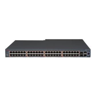
1. Avaya Ethernet Routing Switch 4000 Series.
2. Rack-mounting hardware that includes:
• Rack-mount brackets (2)
• Screws to attach brackets to the switch (8)
• Screws to attach the switch to the equipment rack (2x4)
3. Rubber footpads.
4. AC power cord. (Note: A power cord is not included for the A variant of
the switch)
5. Standard 1.5 foot (46 cm) stacking cable.
6. Documentation includes the Base software license kit, Quick Install poster,
and Regulatory documents.
Note: Field replaceable power supply already installed in the switch. Two field
replaceable power supplies are supported for models ERS 4526T-PWR+, ERS
4550T-PWR+, ERS 4826GTS, ERS 4826GTS-PWR+, ERS 4850GTS, and
ERS 4850GTS-PWR+. One power supply is already installed.
Note: Be sure to order Direct Attach cables and SFP or SFP+ Transceivers
if required.
Model
Primary PSU
ERS 4826GTS,
300w AC power supply
ERS 4850GTS
(replacement order code:
AL1905?03-E5)
ERS 4526T-PWR+,
1000w AC supply
ERS 4550T-PWR+,
(replacement order code:
ERS 4826GTS-PWR+,
AL1905?21-E6)
ERS 4850GTS-PWR+
ERS 4526FX,
The ERS 4500 models contain built-in power supplies.
ERS 4526T,
They do not support field replaceable power supplies.
ERS 4526T-PWR,
ERS 4550T,
ERS 4550T-PWR,
ERS 4524GT,
ERS 4524GT-PWR,
ERS 4526GTX
ERS 4526GTX-PWR,
ERS 4548GT
ERS 4548GT-PWR
PWR
1
3
USB
Status
5
RPS
7
Up
9
11
Speed
Down
Link/Ac
t
13
Base
15
17
2
19
4
6
21
8
23
Link/Ac
Speed
t
10
25
12
27
29
14
31
16
33
18
Speed
20
35
Link/Ac
22
t
37
24
39
26
41
28
43
45
30
47
32
34
45
In Use
Link/Ac
36
t
47
4548
GT
38
40
42
44
46
48
46
48
Console
Optional Secondary PSU
300w AC power supply
(order code: AL1905?03-E5)
1000w AC power supply
(order code: AL1905?21-E6)
2
a. (Optional) Prepare the rack
1. Provide the equivalent of one rack of vertical space for each switch in an EIA or
IEC-standard 19-inch (48.2-centimeter) equipment rack.
2. Ensure that the equipment rack is stable and securely attached to a
permanent structure.
3. Ground the rack to the same grounding electrode used by the power service in the
area. The ground path must be permanent and must not exceed 1 Ohm of
resistance from the rack to the grounding electrode. AVAYA recommends using a
filter or surge suppressor.
b. When you install the switch into a network, ensure to use
the following cables:
• Category 5E or higher specification cabling must be used for 1 Gbps/1000
Mbps operation.
• RJ-45 and DB-9 console port cables and adaptors are as follows:
PEC Code
Name
AL2011022-E6
Avaya RJ-45/DB-9
CONSOLE CABLE
AL2011020-E6
AVAYA RED DB-9
FEMALE TO
RJ-45 ADAPTOR
AL2011021-E6
AVAYA BLUE
DB-9 MALE TO
RJ-45 ADAPTOR
c. Stacking cables
PEC Code
Description (all are RoHS compliant)
AL4518001-E6
4000-SSC HiStack Stacking Cable 46cmm (1.5ft) for Ethernet Routing
Switch 4500 or 4800 series (for use as spare).
AL4518002-E6
4500-SSC HiStack Stacking Cable 1.5 Meters (5ft) for Ethernet Routing
Switch 4500 series spare or for use as return cable for resiliency.
AL4518003-E6
4500-SSC HiStack Stacking Cable 3m (10ft) for Ethernet Routing Switch
4500 series spare or for use as return cable for resiliency.
AL4518004-E6
4000-SSC HiStack Stacking Cable 5m (16.4ft) for Ethernet Routing Switch
4500 or 4800 series (spare or for use as return cable for resiliency).
3
Mounting options
Table or shelf mounting
If you are mounting the ERS 4000 switch on a table or shelf, attach the rubber feet on
the underside of the switch by placing a pad near each corner.
1`
Set the device on a flat surface near an AC power source, making sure there is at least
2 inches (5.1 cm) of space on all sides for proper air flow, and at least 5 inches
(12.7 cm) at the back for power cord clearance.
4
Rack mounting
1. Attach a bracket to each side of the switch.
2. Slide the switch into the rack.
3. Insert and tighten the rack-mount screws.
Short Description
1.8m cable with DB-9 Female for terminal/PC on one
end and RJ-45 for device console port connectivity on
the other.
Converts DB-9 MALE to RJ-45 serial port. The adaptor
can be used for PC or device with DB-9 MALE console
port. Also, can be used with Category 5 RJ-45 straight
cable to provide console connection.
Converts DB-9 FEMALE to RJ-45 serial port. This
adaptor can be used to convert DB-9 of AL2011013-E6
console cable to RJ-45.
Advertisement

Related Manuals for Avaya 4000 Series


Summary of Contents for Avaya 4000 Series
- Page 1 The ground path must be permanent and must not exceed 1 Ohm of Avaya resistance from the rack to the grounding electrode. AVAYA recommends using a filter or surge suppressor. b. When you install the switch into a network, ensure to use the following cables: •...
- Page 2 Depending on your ERS 4000 switch model, the console port is either the RJ-45 port purposes as shown below: outlined with a blue border, or the DB-9 port on the front of your ERS 4000 Series switch (note orientation). Use an RJ-45 to DB-9 cable, or a DB-9 to DB-9 serial cable to connect the switch console port to your management terminal.
Need help?
Do you have a question about the 4000 Series and is the answer not in the manual?
Questions and answers