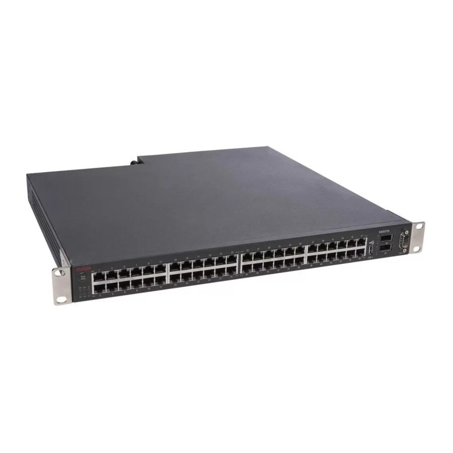
Avaya 5000 Series Installation Manual

Avaya 5000 Series Installation Manual

Ethernet routing switch
Hide thumbs Also See for 5000 Series:
Table of Contents

Advertisement

Avaya Ethernet Routing Switch 5000
Series Installation
6.0
NN47200-300, 04.06 (217461-C, Rev. 04)
December 2010

Advertisement

Table of Contents
loading

Summary of Contents for Avaya 5000 Series

  • Page 1 Avaya Ethernet Routing Switch 5000 Series Installation NN47200-300, 04.06 (217461-C, Rev. 04) December 2010...
  • Page 2 Avaya or the applicable third party. Avaya does not guarantee that these links will work all the time and has no control over the availability of the linked pages.
  • Page 3: Table Of Contents

    Chapter 6: Procedures for installation of the switch............57 Installation preparation............................57 Switch placement............................62 Power connection............................70 Hardware installation verification........................75 Preparations for network connectivity......................79 IP address information configuration.......................81 Stack configuration............................85 Chapter 7: Common procedures....................91 Abandoning a command..........................91 Avaya Ethernet Routing Switch 5000 Series Installation December 2010...
  • Page 4 Avaya Ethernet Routing Switch 5520-24T-PWR and 5520-48T-PWR............95 Power specifications............................96 Chapter 9: Customer Service....................99 Getting technical documentation........................99 Getting product training...........................99 Getting help from a distributor or reseller......................99 Getting technical support from the Avaya Web site..................100 Avaya Ethernet Routing Switch 5000 Series Installation December 2010...
  • Page 5: Chapter 1: Regulatory Information And Safety Precautions

    Further, the equipment has been certified as compliant with the national standards as detailed below. For regulatory statements of conformity and safety precautions and translations for the Ethernet Routing Switch 5600 Series, see Avaya Ethernet Routing Switch 5600 Series Regulatory Information (NN47201-101). National electromagnetic compliance (EMC) statements of...
  • Page 6 EN 55024 statement This is to certify that the Ethernet Routing Switch 5000 Series equipment is shielded against the susceptibility to radio interference in accordance with the application of Council Directive 2004/108/EC.
  • Page 7: National Safety Statements Of Compliance

    European Union countries have been evaluated for compliance. NOM statement (Mexico only) The following information is provided on the devices described in this document in compliance with the safety requirements of the Norma Oficial Méxicana (NOM): Avaya Ethernet Routing Switch 5000 Series Installation December 2010...
  • Page 8 Regulatory information and safety precautions Exporter: Avaya Inc. 4655 Great America Parkway Santa Clara CA 95054 USA Importer: Avaya Communication de México, S.A. de C.V. Av. Presidente Masarik 111 Piso 6, Col. Chapultepec Morales Deleg. Miguel Hidalgo México D.F. 11570...
  • Page 9: National Environmental Statements Of Compliance

    RoHS Directive are Lead (including solder used in PCB’s), Cadmium, Mercury, Hexavalent Chromium, and Bromine. Avaya declares compliance with the European Union (EU) RoHS Directive (2002/95/EC). WEEE Directive Compliance Statement This product at end of life is subject to separate collection and treatment in the EU Member States, Norway, and Switzerland and therefore is marked with the symbol shown at the left.
  • Page 10: Safety Messages

    Se il dispositivo viene installato in un rack, non impilare le unità direttamente una sull’altra. Ogni unità deve essere fissata al rack con le staffe di montaggio appropriate. Le staffe di montaggio non sono state progettate per supportare più unità. Avaya Ethernet Routing Switch 5000 Series Installation December 2010...
  • Page 11 Attenzione: Se nello slot non vengono installati moduli, assicurarsi di mantenere la piastra di copertura metallica in sede sopra lo slot. La rimozione della piastra impedisce la ventilazione e il corretto raffreddamento dell’unità. Avaya Ethernet Routing Switch 5000 Series Installation December 2010...
  • Page 12 Avviso: L’unico modo per disattivare questo dispositivo consiste nello scollegare il cavo di alimentazione. Collegare sempre il cavo di alimentazione ad una presa che sia facilmente e rapidamente accessibile in caso di emergenza. Avaya Ethernet Routing Switch 5000 Series Installation December 2010...
  • Page 13 Senza un’adeguata messa a terra, chiunque tocchi lo switch corre il rischio di ricevere una scossa elettrica. L’assenza di un percorso per la messa a terra verso lo switch può comportare un eccesso di emissioni. Avaya Ethernet Routing Switch 5000 Series Installation December 2010...
  • Page 15: Chapter 2: New In This Release

    Chapter 2: New in this Release The following sections detail what’s new in Avaya Ethernet Routing Switch 5000 Series Installation (NN47200-300) for Release 6.0. • Features on page 15 • Other changes on page 15 Features This document includes Ethernet Routing Switch 5000 Series functionality enhancements and changes provided with the introduction of the 5600 Series switch.
  • Page 17: Chapter 3: Introduction

    Chapter 3: Introduction This document provides the information and procedures required to install the hardware, software, cabling, and power for the Ethernet Routing Switch 5000 Series. Unless otherwise indicated, this information applies to: • Ethernet Routing Switch 5510-24T • Ethernet Routing Switch 5510-48T •...
  • Page 19: Chapter 4: Installation Fundamentals

    • Do not remove the wrist or ankle strap until the installation is complete. With new cable installations, Avaya recommends that the use of an ESD discharge cable to reduce the potential for damage from static that can build up in cables. See...
  • Page 20: Ethernet Routing Switch 5000 Series Models

    Figure 1: ESD cable Ethernet Routing Switch 5000 series models This module describes the 5000 Series switches. The following table lists the different Ethernet Routing Switch 5000 Series models and the key features for each switch. Table 1: 5000 Series Switch Platforms...
  • Page 21 • Stackable Ethernet switch • 1.5 rack units (U) high • Uses modular power supply units and has two field-serviceable power supply receptacles, which support 300W AC or DC power supply modules. Avaya Ethernet Routing Switch 5000 Series Installation December 2010...
  • Page 22 • Uses modular power supply units and has three field-serviceable power supply receptacles, which support 300W AC or DC power supply modules. Ethernet Routing Switch 5698TFD-PWR • 96 fixed 100/1000FX SFP Ethernet ports • Six 10Gbit XFP ports Avaya Ethernet Routing Switch 5000 Series Installation December 2010...
  • Page 23: Common Hardware Features

    • USB 2.0 Type-A port The following figure shows the front panel of the 5698TFD switch. The following figure shows the rear panel of the 5698TFD switch. Not all 5000 Series switches have a USB port on the rear panel. See...
  • Page 24 24 for information about switches that have the rear- panel USB port. Universal Serial Bus ports on the Avaya Ethernet Routing Switch 5000 Series The following switches include a Type A USB port on the front panel adjacent to the console port, as well as a rear panel USB port (mini Type B): •...
  • Page 25: Placement Options And Cables

    58. Placement options You can mount 5000 Series switches on a flat surface such as a table or shelf, or in a rack. Choose the mounting option that best suits your location. The following sections describe the options.
  • Page 26 Do not install a switch on a wall if the switch has a height greater than 1 rack unit (U). Switch installation in an equipment rack, front mount option You can mount 5000 Series switches in a rack with the front panel at the front of the rack. See Installing a front mounted switch in an equipment rack on page 66, to install the switch in a rack.
  • Page 27: Single And Multiple Switch Arrangements

    Stack arrangement on page 27 You can stack any of the 5000 Series switches. You can connect up to eight 5500 Series devices in a stack to provide uninterrupted connectivity for up to 384 ports. This stack is managed as a single unit.
  • Page 28 Cascade Up connector completes the stack connection. Important: To create a stack connection, order the appropriate Ethernet Routing Switch 5000 Series cascade cables to ensure fail-safe stacking. An 18 inch cable is provided with the switch. Ensure you order additional stacking cables of the correct length for a stack of three or more units -- you require one long cable (stack return cable) to complete the loop in a stack from the bottom unit to the top unit.
  • Page 29 If the temporary base unit is not assigned as the new base unit, and the temporary base unit fails, the next unit in the stack order becomes the temporary base unit. This process will continue after successive failures until only two units are left in the stack. Avaya Ethernet Routing Switch 5000 Series Installation December 2010...
  • Page 30: Cascade Down

    In this configuration, the base unit discovers the stack in a cascade down (stack down) direction. The following illustration shows a cascade down (stack down) configuration. Avaya Ethernet Routing Switch 5000 Series Installation December 2010...
  • Page 31 Placement options and cables Figure 4: Cascade down configuration Important: Since many network management software packages assume a cascade down (stack down) configuration, Avaya recommends the usage of this configuration. For stack installation procedures, see Stack configuration on page 85.
  • Page 32: Redundant Cascade Stacking

    Redundant cascade stacking The 5000 Series switches allow a stack of up to 8 units in a pure 5600 Series stack, a 5500 Series, or hybrid stack into a dual-path cascade stack. If any single unit fails or if a cable is accidently disconnected, other units in the stack remain operational without interruption.
  • Page 33: Identifying Cables To Use With The Ethernet Routing Switch

    For stack installation procedures, see Stack configuration on page 85. Identifying cables to use with the Ethernet Routing Switch The following table lists the required cables for a 5000 Series switch and cable specifications. Table 2: Switch cabling requirements Required cable Description...
  • Page 34: Connecting A Transceiver To The Switch Or Switch Stack

    Important: In Autonegotiation mode, the Ethernet Routing Switch 5000 Series switches automatically provide the proper MDI/MDI-X connection on the RJ-45 ports; thereby eliminating the need for crossover cables. When Autonegotiation is disabled on 10/100 ports, they are configured as an MDI-X connection.
  • Page 35 1000BaseCWDM-ZX 1610 nm LC connector, up to 70 km AA1419040- 1000Base-T SFP Category 5 copper unshielded twisted pair (UTP), AA1419043- RJ-45 connector 1000Base-SX DDI SFP 850 nm DDI LC connector AA1419048- Avaya Ethernet Routing Switch 5000 Series Installation December 2010...
  • Page 36: Preparing For Power Requirements Of The Switch

    1310 nm, up to 220 m over MMF, DDI AA1403007- See Avaya Ethernet Routing Switch 5000 Series Installation — SFPs and XFPs - (NN47200-302) for a list of supported SFPs and your latest product-specific release notes. Information contained in the Release Notes takes precedence over any information contained in this document.
  • Page 37 Preparing for power requirements of the switch Avaya Ethernet Routing Switch 5510-24T and 5510-48T This section details the power requirements of the Avaya Ethernet Routing Switch 5510-24T and 5510-48T. The following table lists the power specifications for the Ethernet Routing Switch 5510.
  • Page 38: 5500 Series Power Options

    Installation fundamentals Avaya Ethernet Routing Switch 5530-24TFD This section details the power requirements of the Avaya Ethernet Routing Switch 5530-24TFD. The following table lists the power specifications for the Ethernet Routing Switch 5530-24TFD. Table 6: AC power specifications Input current 1.7 A at 120 VAC or 0.85 A at 240 VAC...
  • Page 39 200 W maximum Avaya Ethernet Redundant Power Supply 15 This module describes the Avaya Ethernet Redundant Power Supply 15 (RPS 15). The RPS 15 is a DC power supply used with the AC power supply to provide DTE power to all of the PoE ports in the Avaya Ethernet Routing Switch 5520.
  • Page 40: 5600 Series Power Options

    Avaya RPS 15. By using the Avaya RPS 15, you have a total of 320W of PoE redundant power, which enables up to 48 ports to be powered at 6.6W.
  • Page 41 5632FD 5632FD 5650TD 5650TD 2.75 5650TD- 10.5 5.25 1000 15.4 5650TD- 5.3 * 2.65 * 600 * 15.4 5650 TD- PWR (2 power supplies) 1000 15.4 5650 TD- PWR DC 5698TFD Avaya Ethernet Routing Switch 5000 Series Installation December 2010...
  • Page 42 Power 5632 - 5632 - 5650 - 5650 - 5650 - 5650 - 5698 - 5698 - 5698 - 5698 - Suppl FD DC TD DC Modul 300W Avaya Ethernet Routing Switch 5000 Series Installation December 2010...
  • Page 43: Ordering The Phone Dongle

    W AC/ 1000 W DC/ For regulatory information about the power supply modules, see Avaya Ethernet Routing Switch 5600 Series — Regulatory Information (NN47201-101). PoE capabilities for 5600 Series switch ports The PoE capability at each 5600 Series switch port is dependant on the power supply modules that you install.
  • Page 44 Installation fundamentals The part number for the Avaya Ethernet Routing Switch 5520 (5520-24T/48T-PWR) universal phone dongle is DY4311046. Avaya Ethernet Routing Switch 5000 Series Installation December 2010...
  • Page 45: Chapter 5: Installing The Switch

    Installation tasks include the procedures required to bring the switch online. The procedures reflect the recommended method to install the 5000 Series switch in the simplest way, with necessary safety precautions. Installation does not include customized configuration, switch maintenance, or switch administration.
  • Page 46 Installation Preparation on page 47 • Switch placement on page 47 • Power connection on page 48 • Hardware installation verification on page 49 • Preparations for network connectivity on page 50 Avaya Ethernet Routing Switch 5000 Series Installation December 2010...
  • Page 47: Installation Preparation

    Verifying environment suitability on page 57 • Verifying the contents of the box on page 60 Switch placement This task flow shows the sequence of procedures you perform to place the switch. Avaya Ethernet Routing Switch 5000 Series Installation December 2010...
  • Page 48: Power Connection

    66 • Installing a rear mounted switch in an equipment rack on page 68 Power connection This task flow shows the sequence of procedures you perform to connect power. Avaya Ethernet Routing Switch 5000 Series Installation December 2010...
  • Page 49: Hardware Installation Verification

    Installing a redundant power supply in a 5500 Series switch on page 72 • Installing DC-DC converter in a 5500 Series switch on page 73 Hardware installation verification Use the following procedures to install the hardware. Avaya Ethernet Routing Switch 5000 Series Installation December 2010...
  • Page 50: Preparations For Network Connectivity

    Installing the switch Hardware Installation Verification Task Flow Navigation: Checking LEDs on page 75 Preparations for network connectivity Use the following procedures to prepare for network connectivity. Avaya Ethernet Routing Switch 5000 Series Installation December 2010...
  • Page 51: Ip Address Information Configuration

    79 • Installing transceivers on page 80 • Connecting a phone dongle IP address information configuration This task flow shows the sequence of procedures you perform to configure IP address information. Avaya Ethernet Routing Switch 5000 Series Installation December 2010...
  • Page 52 Assigning IP parameters using the UI/Mode Select button on page 83 • Assigning IP parameters using Enterprise Device Manager on page 84 • Verifying assigned IP address is reachable on page 85 Avaya Ethernet Routing Switch 5000 Series Installation December 2010...
  • Page 53: Stack Configuration

    Stack configuration Stack configuration This task flow shows the sequence of procedures you perform to configure a stack. Avaya Ethernet Routing Switch 5000 Series Installation December 2010...
  • Page 54 Stack Configuration Task Flow Navigation: • Cabling a stack on page 85 • Selecting a base unit on page 88 • Selecting a base unit using the UI/Mode Select button on page 89 Avaya Ethernet Routing Switch 5000 Series Installation December 2010...
  • Page 55 Setting non-base units using the UI/Mode Select button on page 89 • Resetting a stack using the UI/Mode Select button on page 90 • Hybrid stack recommendations and limitation on page 90 Avaya Ethernet Routing Switch 5000 Series Installation December 2010...
  • Page 57: Chapter 6: Procedures For Installation Of The Switch

    Table 9: Job aid: Ethernet Routing Switch 5600 Series environmental requirements on page 59 Avaya Ethernet Routing Switch 5000 Series Installation December 2010...
  • Page 58 Between -1,000 and and 10,000 feet and 10,000 feet 40,000 feet (-340.8 (-304.8 and 3048 (-304.8 and 3048 and 12,192 meters) meters) above sea meters) above sea above sea level. level. level. Avaya Ethernet Routing Switch 5000 Series Installation December 2010...
  • Page 59 • No excessive dust in the environment. • An adequate power source is located within 6 feet (1.83 meters) of the switch. One 15-amp circuit is required for each power supply. Avaya Ethernet Routing Switch 5000 Series Installation December 2010...
  • Page 60: Verifying The Contents Of The Box

    1. Avaya Ethernet Routing Switch 5500 Series 2. Rack-mounting hardware that includes: • Rack-mount brackets. Note: The Avaya Ethernet Routing Switch 5530-24TFD offers 24 inch rack mounting brackets. • Screws for attaching brackets to the switch • Screws for attaching the switch to the equipment rack 3.
  • Page 61 • Screws for attaching the brackets to the equipment rack 3. Stacking cable 4. Rubber footpads 5. Country-specific AC power cord or DC adapter 6. Power supply module and related documentation Avaya Ethernet Routing Switch 5000 Series Installation December 2010...
  • Page 62: Switch Placement

    This procedure describes how to mount 5000 Series switches on a table or a shelf. A single 5000 Series Switch can be installed on any flat surface. The surface should be able to support the combined weight of the switch and attached cables; between 15 and 20 lbs (7 to 9 kg) for a 5500 Series switch, and between 21 and 33 lbs (9.5 to 15 kg) for a 5600 Series...
  • Page 63 2. Set the switch on a table or shelf as shown in Figure 10: Ethernet Routing Switch 5000 Series on a table or shelf on page 64. Allow at least 2 inches (5.1 centimeters) on each side for proper ventilation and at least 5 inches (12.7 centimeters) at the back for power cord clearance.
  • Page 64: Mounting On A Wall

    30 lbs (13.6 kg). Ensure you choose fasteners appropriate for the weight of the unit. One person can lift and install the 5500 Series switch. Avaya recommends that two people lift and install a 5600 Series switch.
  • Page 65 Switch placement Job Aid The following figures show the wall mount bracket detail. Figure 11: Wall mount bracket detail The following figures show the wall mount screw location. Avaya Ethernet Routing Switch 5000 Series Installation December 2010...
  • Page 66: Installing A Front Mounted Switch In An Equipment Rack

    2. Slide the switch into the rack as illustrated in Figure 14: Rack mount on page 68. Insert and tighten the rack-mount screws with a #2 Phillips screwdriver. Job Aid The following figures show the bracket installation. Avaya Ethernet Routing Switch 5000 Series Installation December 2010...
  • Page 67 Switch placement Figure 13: Bracket installation The following figures show the rack mount. Avaya Ethernet Routing Switch 5000 Series Installation December 2010...
  • Page 68: Installing A Rear Mounted Switch In An Equipment Rack

    Figure 15: Attaching rear mounted switch brackets on page 69. The bracket with the round holes goes on the right side of the switch where the round fan vents are located. Avaya Ethernet Routing Switch 5000 Series Installation December 2010...
  • Page 69 Figure 15: Attaching rear mounted switch brackets 2. Slide the switch into the rack as shown in Figure 16: Rear mounted switch configuration on page 70. Insert and tighten the rack-mount screws with a #2 Phillips screwdriver. Avaya Ethernet Routing Switch 5000 Series Installation December 2010...
  • Page 70: Power Connection

    Installing a power supply module in a 5600 Series switch This procedure describes the step necessary to install a power supply module in a 5600 Series switch. Prerequisites #2 Phillips screwdriver Avaya Ethernet Routing Switch 5000 Series Installation December 2010...
  • Page 71: Connecting An Ac Cord To Switch

    Electrostatic alert: To prevent damage from electrostatic discharge, always wear an antistatic wrist strap connected to an ESD jack when performing maintenance on a 5000 Series switch. Ensure that the wrist strap makes contact with your skin. 1. Use a Phillips screwdriver to loosen the two screws that secure the metal plate that covers the slot in which you want to install the power supply module.
  • Page 72: Installing A Redundant Power Supply In A 5500 Series Switch

    AC power outlet. The following figure illustrates connecting the AC power cord to the switch back panel. Important: The 5000 Series switches do not have an AC power switch. When the power cord is connected to a suitable AC power outlet, the switch powers up immediately. Warning: Disconnecting the AC power cord is the only way to turn off AC power to the 5000 Series switches.
  • Page 73 5. Repeat these steps for each power supply module that you must install. Installing DC-DC converter in a 5500 Series switch This procedure describes the steps used to install a DC-DC converter. This procedures applies only to 5500 Series switches. Avaya Ethernet Routing Switch 5000 Series Installation December 2010...
  • Page 74: Connecting A Dc Power Source To A 5600 Series Switch

    Warning: Removal of the power cord is the only way to turn off power to 5000 Series switches. The power cord must always be connected in a location that can be accessed quickly and safely in case of an emergency.
  • Page 75: Hardware Installation Verification

    4. Attach the opposite ends of the leads to a –48V DC power source. Hardware installation verification Checking LEDs This procedure describes how to check and interpret LEDs on the 5000 Series switches. To check and interpret front panel LEDs, compare the LEDs to the tables in the Job Aids section.
  • Page 76 System will reset in less than 1 second. To stop the reset, release UI push button. Note: The UI button is labeled Mode Select on Avaya branded equipment. The switch is not connected to an AC power source or the power supply unit is not supplying power.
  • Page 77 1000 Mbps - PoE is on 10 Mbps or No link or Admin disabled or PoE is off. Refer to the speed setting configured for this port to determine the specific state. Avaya Ethernet Routing Switch 5000 Series Installation December 2010...
  • Page 78 XFP has been installed. No Signal Detected or XFP in Reset. Both Off No XFP installed. The Amber LEDs are usually only used during the boot process. Under normal operation, Green is the only color the XFP LED should emit. Avaya Ethernet Routing Switch 5000 Series Installation December 2010...
  • Page 79: Preparations For Network Connectivity

    Preparations for network connectivity Preparations for network connectivity The following section contains procedures used to prepare 5000 Series switches for network connectivity. Cabling a standalone switch This procedure describes the steps used to cable a standalone switch. Prerequisites The following table lists the required cables for an Avaya Ethernet Routing Switch 5500 Series and their specifications.
  • Page 80: Installing Transceivers

    5. Remove the dust cover from the transceiver optical bores. Job Aid The following graphic shows and SFP tranceiver. Avaya Ethernet Routing Switch 5000 Series Installation December 2010...
  • Page 81: Ip Address Information Configuration

    2. Connect the other end of the serial cable to the DB-9 connector on the switch. 3. Turn the terminal on. Accessing the console menu This procedure describes the steps used to access the console menu. Avaya Ethernet Routing Switch 5000 Series Installation December 2010...
  • Page 82: Assigning Ip Parameters Using The Console Menu

    3. Connect to the switch using the terminal or terminal emulation application. 4. After the Avaya banner is displayed, press CTRL + Y to display the main menu. The version of the main menu displayed is dependent on whether the switch is part of a standalone or stacked switch configuration.
  • Page 83 This procedure describes the steps to assign IP parameters using the UI button. Note: The UI button is labeled Mode Select on Avaya branded equipment. 1. Press and hold the UI button for 3 seconds. The unit enters configuration mode. The Status LED changes to a blinking green status.
  • Page 84 6. In the In-Band Subnet Mask dialog box, type a subnet mask. 7. In the Default Gateway dialog box, type an IP address. 8. Click Apply. Note: For further switch configuration information, see Avaya Ethernet Routing Switch 5000 Series Configuration-System (NN47200–500). Avaya Ethernet Routing Switch 5000 Series Installation December 2010...
  • Page 85: Stack Configuration

    • Ensure the terminal from which you ping the switch is on the same network as the switch. Ping the 5000 Series switch from a terminal or workstation that is on the same network. If the network device sends a ping reply, a message indicates that the specified IP address is alive and can communicate with other devices.
  • Page 86: Stack Configurations

    USB 2.0 compliant cable with a USB Type A connector on both ends. Important: In Autonegotiation mode, the Avaya Ethernet Routing Switch 5500 Series automatically provides the proper MDI/MDI-X connection on the RJ-45 ports; thereby eliminating the need for crossover cables. When Autonegotiation is disabled on 10/100 ports, they are configured as an MDI-X connection.
  • Page 87 Stack configuration Figure 19: Job aid: 5500 Series stack connector Figure 20: Job aid: 5600 Series stack connector Figure 21: Connecting cascade cables Figure 22: Cascade up stack configuration Avaya Ethernet Routing Switch 5000 Series Installation December 2010...
  • Page 88: Selecting A Base Unit

    1. Determine which unit will be the base unit. 2. Locate the Unit Select switch on the rear panel. 3. Slide the switch to the right to designate it as the base unit. Avaya Ethernet Routing Switch 5000 Series Installation December 2010...
  • Page 89 This procedure describes the steps necessary to set the base unit using the UI button. Note: The UI button is labeled Mode Select on Avaya branded equipment. 1. Press and hold the UI button for three seconds. The unit is now in configuration mode.
  • Page 90 The following procedure describes the steps to reset the stack using the UI button. Note: The UI button is labeled Mode Select on Avaya branded equipment. 1. Press and hold the UI button for three seconds. The unit is now in configuration mode. The color and status of the Status LED turns to blinking green.
  • Page 91: Chapter 7: Common Procedures

    This procedure describes how to abandon a command entered using the UI/Mode Select button. Note: The UI button is labeled Mode Select on Avaya branded equipment. Abandoning a command entered using the UI/Mode Select button 1. Do not confirm a command within approximately twenty seconds after you enter the command and the system ignores the input.
  • Page 93: Chapter 8: Installation Reference

    The following section outlines the connector pin assignments for the RJ-45 connectors in the Avaya Ethernet Routing Switch 5500 Series switches. Avaya Ethernet Routing Switch 5510 and 5530 The following table outlines the RJ-45 connector pin assignments in the Avaya Ethernet Routing Switch 5510, 5530, and 5600 Series non-PoE switches. Connector...
  • Page 94: Console Port Pin Assignments

    TP0- TP3+ TP2+ TP3- TP2- Console port pin assignments The following section outlines the console port pin assignments in the Avaya Ethernet Routing Switch 5500 Series. Table 17: Console port pin assignments Connector Pin number Signal Carrier detect (not used)
  • Page 95: Avaya Ethernet Routing Switch 5520-24T-Pwr And 5520-48T-Pwr

    • 50 Hz • Single Phase Avaya Ethernet Routing Switch 5520-24T-PWR and 5520-48T-PWR The following table outlines the RJ-45 connector pin assignments in the Avaya Ethernet Routing Switch 5510, 5530, and 5600 Series PoE switches. Connector Pin Number Signal for...
  • Page 96: Power Specifications

    • Avaya Ethernet DC-DC converter module on page 97 Avaya Ethernet Power Supply 10 power specification The following table shows the power specifications for the Avaya Ethernet Redundant Power Supply 10 (RPS 10). Table 19: DC power specifications Output current 4.2 A maximum...
  • Page 97 Output power 600 W Avaya Ethernet DC-DC converter module This module describes where to find the power specifications for the Avaya Ethernet DC-DC converter module. The Ethernet Routing Switch 5510 requires an additional DC-DC converter module to use the Avaya Ethernet Routing Switch Redundant Power Supply Model 15 (RPS 15). This module connects the RPS 15 to the Ethernet Routing Switch 5510 but is not required for other switches in the 5500 Series.
  • Page 99: Chapter 9: Customer Service

    Chapter 9: Customer Service Visit the Avaya Web site to access the complete range of services and support that Avaya provides. Go www.avaya.com or go to one of the pages listed in the following sections. Navigation • Getting technical documentation on page 99 •...
  • Page 100: Getting Technical Support From The Avaya Web Site

    Customer Service Getting technical support from the Avaya Web site The easiest and most effective way to get technical support for Avaya products is from the Avaya Technical Support Web site at www.avaya.com/support. Avaya Ethernet Routing Switch 5000 Series Installation...

Table of Contents