Table of Contents
Advertisement
Quick Links
- 1 Chapter 1: Introduction
- 2 Chapter 4: Installing Ethernet Routing Switch 4900 Series
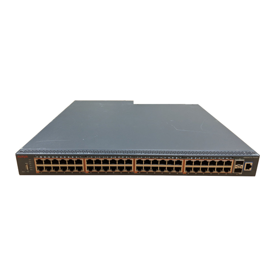
- 3 Ethernet Routing Switch 4900 Series Models
- 4 Technical Specifications
- 5 Console Port Pin Assignments
- 6 Switch Installation
- 7 Stack Configurations
- 8 Switch Led State Indicators
- Download this manual
See also:
Manual
Advertisement
Table of Contents

Related Manuals for Avaya 4900 Series


Summary of Contents for Avaya 4900 Series
- Page 1 Installing Avaya Ethernet Routing Switch 4900 Series Release 7.1 NN47212-301 Issue 01.02 February 2016...
-
Page 2: Table Of Contents
.................... 6 Subscribing to e-notifications .......................... 8 Support Chapter 2: New in this document.................... 9 Chapter 3: Preinstallation checklist.................. 10 Chapter 4: Installing Ethernet Routing Switch 4900 Series.......... 12 ....................... 12 Installation checklist ................ 12 Ethernet Routing Switch 4900 Series models ..................... 14 Common hardware features .................. - Page 3 Contents .................... 50 Switch LED state indicators .................... 51 Port LED state indicators Appendix A: Translations of safety messages.............. 53 ........................ 53 Safety messages February 2016 Installing Avaya Ethernet Routing Switch 4900 Series Comments on this document? infodev@avaya.com...
-
Page 4: Chapter 1: Introduction
Release Notes for Avaya Ethernet Routing Switch 4900 and 5900 Series, NN47211-400. For more information about how to configure security, see Configuring Security on Avaya Ethernet Routing Switch 4900 and 5900 Series, NN47211-505. For the current documentation, see the Avaya Support web site: www.avaya.com/support. -
Page 5: Searching A Documentation Collection
Avaya Mentor videos provide technical content on how to install, configure, and troubleshoot Avaya products. About this task Videos are available on the Avaya Support website, listed under the video document type, and on the Avaya-run channel on YouTube. Procedure •... -
Page 6: Subscribing To E-Notifications
Application & Technical Notes for Virtual Services Platform 7000. Procedure 1. In an Internet browser, go to https://support.avaya.com. 2. Type your username and password, and then click Login. 3. Under My Information, select SSO login Profile. - Page 7 8. Scroll through the list, and then select the product name. 9. Select a release version. 10. Select the check box next to the required documentation types. February 2016 Installing Avaya Ethernet Routing Switch 4900 Series Comments on this document? infodev@avaya.com...
-
Page 8: Support
Chat with live agents to get answers to questions, or request an agent to connect you to a support team if an issue requires additional expertise. February 2016 Installing Avaya Ethernet Routing Switch 4900 Series Comments on this document? infodev@avaya.com... -
Page 9: Chapter 2: New In This Document
Installing Avaya Ethernet Routing Switch 4900 Series, NN47212-301 is a new document for 7.1 so all the features are new in this release. See Release Notes for Avaya Ethernet Routing Switch 4900 and 5900 Series for a full list of features. -
Page 10: Chapter 3: Preinstallation Checklist
Chapter 3: Preinstallation checklist Before you install the Ethernet Routing Switch 4900 Series, make sure that you complete the tasks in the preinstallation checklist. Task Description Review the technical specification for the For the physical, electrical, and switch. Make sure that the area where... - Page 11 1 Ohm of resistance from the rack to the grounding electrode. Installing the switch in an equipment rack on page 26. February 2016 Installing Avaya Ethernet Routing Switch 4900 Series Comments on this document? infodev@avaya.com...
-
Page 12: Chapter 4: Installing Ethernet Routing Switch 4900 Series
This section provides information about the switches in Ethernet Routing Switch 4900 Series. Ethernet Routing Switch 4900 Series models The following table lists the different Ethernet Routing Switch 4900 Series models and the key features for each switch. February 2016 Installing Avaya Ethernet Routing Switch 4900 Series Comments on this document? infodev@avaya.com... - Page 13 See the following for details: “A”: No power cord included. “B”: Includes European “Schuko” power cord common in Austria, Belgium, Finland, France, Germany, The Netherlands, Norway, and Sweden. Table continues… February 2016 Installing Avaya Ethernet Routing Switch 4900 Series Comments on this document? infodev@avaya.com...
-
Page 14: Common Hardware Features
Depending on the switch model, a 250 W or 1025 W PSU and .5 m stacking cable is provided for all switches. Common hardware features The following hardware features are part of all switches in ERS 4900 Series: • Standard ERS 19 inch rack mount hole pattern allowing horizontal or vertical, flush or offset, front or rear mount options •... -
Page 15: Electrostatic Discharge Prevention
To protect the Avaya Ethernet Routing Switch against ESD damage, take the following preventive measures before connecting any data cables to the device: •... -
Page 16: Technical Specifications
• Do not remove the wrist or ankle strap until the installation is complete. With new cable installations, Avaya recommends that the use of an ESD discharge cable to reduce the potential for damage from static that can build up in cables. See the following figure. -
Page 17: Power Specifications
Thermal Power (margined by 10%) rating supplies (BTUs/hr maximum) Rated Line voltage Watts Amps (Total) ERS 4950GTS 250 W 200–240 VAC 53.14 0.30 181.31 Table continues… February 2016 Installing Avaya Ethernet Routing Switch 4900 Series Comments on this document? infodev@avaya.com... - Page 18 ERS 4926GTS 34.9 40.0 34.9 ERS 4950GTS-PWR+ 65.9 73.4 382.0 65.9 ERS 4926GTS-PWR+ 51.4 55.8 208.8 51.5 The following table describes the Power over Ethernet (PoE+) specifications. February 2016 Installing Avaya Ethernet Routing Switch 4900 Series Comments on this document? infodev@avaya.com...
-
Page 19: Mtbf Values
30 W 720 W 24 ports at 30 W MTBF values The following table lists the MTBF values for the switches in ERS 4900 Series in combination with one or two PSUs. Model Number of PSUs Power Supply rating MTBF (hours) -
Page 20: Ac Power Cord Specifications
• BS1363 male plug with fuse • 50 Hz • Harmonized cord • Single Phase Australia: • 240 VAC • AS3112-1981 male plug • 50 Hz • Single Phase February 2016 Installing Avaya Ethernet Routing Switch 4900 Series Comments on this document? infodev@avaya.com... -
Page 21: Universal Serial Bus Ports
Receive Data+/power– RX–/power– Receive Data–/power– TX+/power+ Transmit Data+/power+ Not applicable Not applicable Not applicable Not applicable TX–/power+ Transmit Data–/power+ Not applicable Not applicable Not applicable Not applicable February 2016 Installing Avaya Ethernet Routing Switch 4900 Series Comments on this document? infodev@avaya.com... -
Page 22: Console Port Pin Assignments
Verifying the package contents For each Ethernet Routing Switch 4900 Series, verify the package contents with the items in the following figure to ensure you have received all components. If any components are missing, contact the vendor where you purchased the switch. - Page 23 AC power cord specifications on page 20. Note: A power cord is not included for the A variant of the switch. Stacking cable 0.5 m Table continues… February 2016 Installing Avaya Ethernet Routing Switch 4900 Series Comments on this document? infodev@avaya.com...
- Page 24 Table 11: PSU specifications Switch Model Primary PSU Optional Secondary PSU ERS 4950GTS, ERS 4926GTS 250W AC power supply 250W AC Power Supply (order code: AL1905?09-E6) Table continues… February 2016 Installing Avaya Ethernet Routing Switch 4900 Series Comments on this document? infodev@avaya.com...
-
Page 25: Cable Requirements
1025W AC power supply 4926GTS-PWR+ (replacement order code: (order code: AL1905?19-E6) AL1905?19-E6) Cable requirements The following table describes the cables required for Ethernet Routing Switch 4900 Series. Table 12: Stacking cables Description Material code Stacking cable 0.5 m 700511668 Stacking cable 1.5 m 700511669 Stacking cable 3.0 m... -
Page 26: Switch Installation
The ground path must be permanent and must not exceed 1 Ohm of resistance from the rack to the grounding electrode. Note: Avaya does not supply the bolts used to secure the switch to the rack. Ensure you obtain the appropriate bolts to secure the switch to your specific rack before you begin. Caution: When you mount the device in a rack, do not stack units directly on top of one another. - Page 27 Switch installation Figure 4: Front-mounted rack bracket installation February 2016 Installing Avaya Ethernet Routing Switch 4900 Series Comments on this document? infodev@avaya.com...
- Page 28 Installing Ethernet Routing Switch 4900 Series Figure 5: Rear-mounted rack bracket installation 3. Slide the switch into the rack. 4. Insert and tighten the rack mount screws. February 2016 Installing Avaya Ethernet Routing Switch 4900 Series Comments on this document? infodev@avaya.com...
- Page 29 Switch installation Figure 6: Front-mounted rack installation February 2016 Installing Avaya Ethernet Routing Switch 4900 Series Comments on this document? infodev@avaya.com...
-
Page 30: Installing Optional Four-Post Rack-Mount Brackets
- Space of 2.8 inches (7.1 centimeters) for each switch in an E1A or 1EC standard 19 inch (48.2 centimeter) equipment rack and T1A 23 inch (58.5 centimeter) equipment rack. February 2016 Installing Avaya Ethernet Routing Switch 4900 Series Comments on this document? infodev@avaya.com... - Page 31 1. Attach a front bracket to each guide bracket with four 8.5 mm length flat head machine screws. 2. Attach the guide brackets to the switch chassis. February 2016 Installing Avaya Ethernet Routing Switch 4900 Series Comments on this document? infodev@avaya.com...
- Page 32 Use four M4 x 5.5 mm undercut flat-head hex machine screws to attach the rear of each guide bracket to the switch chassis. b. Verify that the rear screws sit flush in the guide brackets. February 2016 Installing Avaya Ethernet Routing Switch 4900 Series Comments on this document? infodev@avaya.com...
- Page 33 Slide a rear mounting bracket into each guide bracket channel until flush with the rear rack posts. b. Secure the rear mounting brackets to the switch chassis with the pan-head screws. February 2016 Installing Avaya Ethernet Routing Switch 4900 Series Comments on this document? infodev@avaya.com...
-
Page 34: Installing The Secondary Power Supply
To prevent damage from electrostatic discharge, always wear an antistatic wrist strap connected to an ESD jack when performing maintenance on a switch. Ensure that the wrist strap makes contact with your skin. February 2016 Installing Avaya Ethernet Routing Switch 4900 Series Comments on this document? infodev@avaya.com... -
Page 35: Connecting Switch To Ac Power
Checking Light Emitting Diode on the switch on page 49. Connecting a transceiver to the switch or switch stack The following sections describe small form factor pluggable (SFP) transceivers. February 2016 Installing Avaya Ethernet Routing Switch 4900 Series Comments on this document? infodev@avaya.com... -
Page 36: Installing Sfp Transceivers
5. Remove the dust cover from the transceiver optical bores. Example The following graphic shows an SFP transceiver. February 2016 Installing Avaya Ethernet Routing Switch 4900 Series Comments on this document? infodev@avaya.com... -
Page 37: Removing Of Sfp Transceivers
1. Disconnect the network fiber cable from the transceiver. 2. Use the locking mechanism on the transceiver to release it. The locking mechanism varies from model to model as illustrated below. February 2016 Installing Avaya Ethernet Routing Switch 4900 Series Comments on this document? infodev@avaya.com... -
Page 38: Supported Optical Devices
Important: Avaya recommends that you use Avaya branded SFP and SFP+ transceivers as they undergo extensive qualification and testing. Avaya is not responsible for any problems that arise from using non-Avaya branded SFP and SFP+ transceivers. - Page 39 Model Description Part number Important: Avaya supports SFP transceivers with the following part numbers: AA1419013-E5, AA1419014-E5, AA1419015-E5, and AA1419025-E5 to AA1419040-E5. However, Avaya strongly recommends using the newer DDI versions of these SFP transceivers. 1000BASE-T SFP gigabit Ethernet, RJ-45 connector...
- Page 40 E6** These transceivers have reached end-of-sale (EOS). For more information about EOS transceivers, and recommended replacements for your product, Locating end of sale notices on page 42. Table continues… February 2016 Installing Avaya Ethernet Routing Switch 4900 Series Comments on this document? infodev@avaya.com...
- Page 41 Small form-factor pluggable plus (SFP+) transceivers SFP+ transceivers are hot-swappable input and output enhancement components that allow 10 gigabit connections. All Avaya SFP+ transceivers use Lucent connectors (LC) to provide precision keying and low interface losses. The following table lists and describes the Avaya SFP+ models.
-
Page 42: Stacking
6. Select the End of Sale notice to view the information. Stacking The switch provides fail-safe stackability. You can connect up to eight 4900 series devices in a stack to provide uninterrupted connectivity for up to 400 ports. You can manage the stack as a single unit. - Page 43 Failure to use this configuration can result in loss of connectivity. Important: In the Unit 1, set the Base unit select switch position to Base. February 2016 Installing Avaya Ethernet Routing Switch 4900 Series Comments on this document? infodev@avaya.com...
- Page 44 This process continues after successive failures until only two units are left in the stack. February 2016 Installing Avaya Ethernet Routing Switch 4900 Series Comments on this document? infodev@avaya.com...
- Page 45 • The Cascade Down LED for Unit 2 and the Cascade Up LED for Unit 4 turn amber to indicate an error. • The remaining stack units remain connected and continue to operate. February 2016 Installing Avaya Ethernet Routing Switch 4900 Series Comments on this document? infodev@avaya.com...
-
Page 46: Connecting Switches In A Stack
Note: Avaya recommends that you use a Cascade Down configuration. Before you begin Order the appropriate Avaya Ethernet Routing Switch 4900 Series cascade cables to ensure fail- safe stacking. For more information, see Cable requirements on page 25. - Page 47 In a cascade up (stack up) configuration, the base unit is physically the bottom unit in the stack. The cable connected to the Cascade Up connector of the base unit terminates in the Cascade Down February 2016 Installing Avaya Ethernet Routing Switch 4900 Series Comments on this document? infodev@avaya.com...
- Page 48 3. Cascade or Stack Cable 4. Cascade/Stack Cable (Return cable to make stack resilient. Use longer Stack Cable if required) Figure 13: Cascade Up (Stack Up) configuration February 2016 Installing Avaya Ethernet Routing Switch 4900 Series Comments on this document? infodev@avaya.com...
-
Page 49: Replacing Or Adding A Stack Unit
The figures and tables in the following sections describe the LEDs on the switch. The tables describe LED operation for a switch that finishes the power-on self-test. February 2016 Installing Avaya Ethernet Routing Switch 4900 Series Comments on this document? infodev@avaya.com... -
Page 50: Switch Led State Indicators
The switch was not allowed to join the stack. Check the switch logs. The switch is not the base unit or temporary base unit, or the switch is operating in stand-alone mode. February 2016 Installing Avaya Ethernet Routing Switch 4900 Series Comments on this document? infodev@avaya.com... -
Page 51: Port Led State Indicators
Green, Blink Not applicable. Green, Steady The SFP port and the transmit port are active. Amber, Blink Not applicable. Amber, Steady SFP Installed—TX Port Inactive Table continues… February 2016 Installing Avaya Ethernet Routing Switch 4900 Series Comments on this document? infodev@avaya.com... - Page 52 100BaseTX) the port link LED may indicate a link, but the switch does not establish a link. Connect ports using the same set speed or use auto-negotiation on each switch. February 2016 Installing Avaya Ethernet Routing Switch 4900 Series Comments on this document? infodev@avaya.com...
-
Page 53: Appendix A: Translations Of Safety Messages
Se il dispositivo viene installato in un rack, non impilare le unità direttamente una sull’altra. Ogni unità deve essere fissata al rack con le staffe di montaggio appropriate. Le staffe di montaggio non sono state progettate per supportare più unità. February 2016 Installing Avaya Ethernet Routing Switch 4900 Series Comments on this document? infodev@avaya.com... - Page 54 Attenzione: Se nello slot non vengono installati moduli, assicurarsi di mantenere la piastra di copertura metallica in sede sopra lo slot. La rimozione della piastra impedisce la ventilazione e il corretto raffreddamento dell’unità. February 2016 Installing Avaya Ethernet Routing Switch 4900 Series Comments on this document? infodev@avaya.com...
- Page 55 Use only power cords that have a grounding path. Without a proper ground, a person who touches the switch is in danger of receiving an electrical shock. Lack of a grounding path to the switch may result in excessive emissions. February 2016 Installing Avaya Ethernet Routing Switch 4900 Series Comments on this document? infodev@avaya.com...
- Page 56 Senza un’adeguata messa a terra, chiunque tocchi lo switch corre il rischio di ricevere una scossa elettrica. L’assenza di un percorso per la messa a terra verso lo switch può comportare un eccesso di emissioni. February 2016 Installing Avaya Ethernet Routing Switch 4900 Series Comments on this document? infodev@avaya.com...
- Page 57 Index Console pin assignments .............22 RJ-45 pin assignments ............support ...................8 Universal Serial Bus (USB) ports .........21 USB ports ................videos ..................February 2016 Installing Avaya Ethernet Routing Switch 4900 Series Comments on this document? infodev@avaya.com...
Need help?
Do you have a question about the 4900 Series and is the answer not in the manual?
Questions and answers