Page 1
Installing Avaya Virtual Services Platform 7000 Series Release 10.3.2 NN47202-300 Issue 07.01 August 2014...
Page 2
INSTALLS AVAYA SOFTWARE, PURCHASED FROM AVAYA INC., written consent of Avaya can be a criminal, as well as a civil offense ANY AVAYA AFFILIATE, OR AN AVAYA CHANNEL PARTNER (AS under the applicable law.
Page 3
Product or Hosted Service notices and articles, or to report a problem with your Avaya Product or Hosted Service. For a list of support telephone numbers and contact addresses, go to the Avaya Support website: http://support.avaya.com (or such successor site as designated by Avaya), scroll to the bottom of the page, and select Contact Avaya Support.
Services Platform 7000 Series hardware. Related resources Documentation For a list of the documentation for this product, see Documentation Roadmap Reference for Avaya Virtual Services Platform 7000 Series, NN47202–103. Training Ongoing product training is available. For more information or to register, see http://avaya- learning.com/.
Support About this task Videos are available on the Avaya Support web site, listed under the video document type, and on the Avaya-run channel on YouTube. Procedure • To find videos on the Avaya Support web site, go to http://support.avaya.com, select the product name, and select the videos checkbox to see a list of available videos.
Page 8
6. Click Search. The search results show the number of documents and instances found. You can sort the search results by Relevance Ranking, Date Modified, Filename, or Location. The default is Relevance Ranking. Installing Avaya VSP 7000 Series August 2014 Comments? infodev@avaya.com...
See the following sections for information about feature changes. 7002QQ MDA Feature Pack Release 10.3.2 introduces the 7002QQ MDA. This MDA adds two 40GBase, Quad (4- channel) Small Form Factor Pluggable Plus (QSFP+) ports to VSP 7000 Series switches as primary client interfaces. Note: When a 40 Gigabyte MDA is inserted for the first time, a reset is required.
Media Dependent Adapter on page 59. VSP 7024XT Feature Pack Release 10.3.1 introduces the VSP 7024XT switch to the VSP 7000 Series. This switch supports 24 x 10GBase-T ports and one Modular Dependent Adapter (MDA) as primary client interfaces. For more information about the VSP 7024XT, see the following sections: •...
They are also Digital Diagnostic Interfaces (DDI) that support Digital Diagnostic Monitoring (DDM). DDM allows the VSP 7000 to monitor SFP laser operating characteristics. For more information, see Small-Form-Factor-Pluggable transceivers on page 53. August 2014 Installing Avaya VSP 7000 Series Comments? infodev@avaya.com...
Fiber optic equipment can emit laser or infrared light that can injure your eyes. Never look into an optical fiber or connector port. Always assume that fiber optic cables are connected to a light source. Installing Avaya VSP 7000 Series August 2014 Comments? infodev@avaya.com...
Page 13
August 2014 Installing Avaya VSP 7000 Series Comments? infodev@avaya.com...
Chapter 4: Installation preparation VSP 7000 Series switch models The Avaya Virtual Services Platform (VSP) 7000 Series includes the following switch models: • VSP 7024XLS — supports 24 x 10 Gigabit SFP+ ports and one Modular Data Adapter (MDA) as primary client interfaces. The VSP 7024XLS provides high–density 10–Gigabit connectivity,...
The following figure shows VSP 7000 Series cooling fan trays. August 2014 Installing Avaya VSP 7000 Series...
Page 16
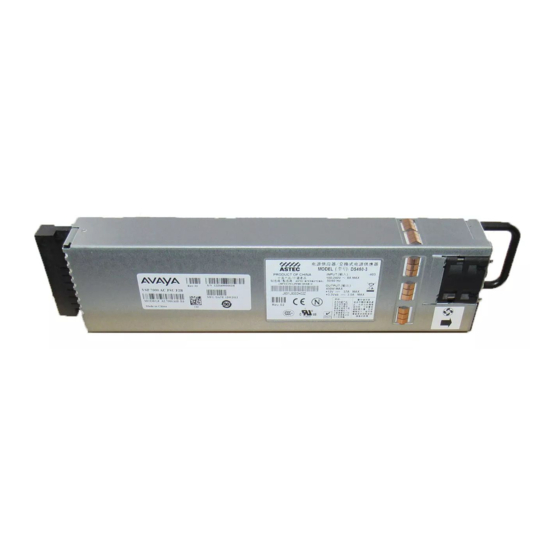
If you are using front to back cooling or back to front cooling, ensure that you use compatible power supplies that match the cooling fan airflow. The following figures show VSP 7000 Series AC and DC power supplies. Installing Avaya VSP 7000 Series August 2014 Comments? infodev@avaya.com...
Page 17
Figure 3: DC power supply Redundant power supply configurations If you install two power supplies for redundancy, the switch can perform load sharing. You can hot-swap power supplies for nonstop, uninterrupted switch operation. August 2014 Installing Avaya VSP 7000 Series Comments? infodev@avaya.com...
The fan trays and power supplies do not support the ability to change their airflow direction. Avaya recommends that you install the first power supply in PSU1 to determine the airflow direction.
After you install the two fan trays and at least one power supply, you can install and connect power to the switch. Power specifications The VSP 7000 Series switches support the following power supply configurations: • One AC power supply • One DC power supply •...
Note: VSP 7000 Series switches do not have a power switch. When you connect the AC power cord to a suitable AC power outlet, the switch powers up immediately. Ensure that you connect the AC power cord to the back of the switch, and then connect the cord to a power outlet.
Page 21
United Kingdom 240 VAC • BS1363 male plug with fuse 50 Hz • Harmonized cord Single Phase Australia 240 VAC AS3112–1981 male plug 50 Hz Single phase August 2014 Installing Avaya VSP 7000 Series Comments? infodev@avaya.com...
The switch will power on immediately when it is connected to a suitable AC power source. The switch does not have a power switch. 2. Plug the male end of the AC power cord into a suitable AC power outlet. Installing Avaya VSP 7000 Series August 2014 Comments? infodev@avaya.com...
Note: VSP 7000 Series switches do not have a power switch. Ensure that your DC power source is off when connecting DC power cables to the back of the switch power supply. Verify all terminal connections, and then connect the DC power cables to your DC power source.
Perform the following procedure to connect a DC power source to the switch. Before you begin Ensure the DC power source is switched off. Ensure the switch power supply supports DC power input. Installing Avaya VSP 7000 Series August 2014 Comments? infodev@avaya.com...
Page 25
2. Connect the DC leads to the positive and negative DC power supply terminals. 3. Tighten the screws on the terminal blocks to secure all cables. 4. Attach the opposite ends of the DC leads to a 48–volt DC power source. August 2014 Installing Avaya VSP 7000 Series Comments? infodev@avaya.com...
The switch software monitors the internal temperature and generates log and SNMP traps to indicate that the switch is running above the high-temperature threshold and is approaching a critical over-temperature fault. Installing Avaya VSP 7000 Series August 2014 Comments? infodev@avaya.com...
5. Verify that the switch is securely fastened to the rack. You can proceed with the installation by connecting power and network connections to the switch. Example The figures in this example show front and rear rack-mount bracket installation options. August 2014 Installing Avaya VSP 7000 Series Comments? infodev@avaya.com...
Page 28
Switch installation Figure 7: Front-mounted rack bracket installation options Installing Avaya VSP 7000 Series August 2014 Comments? infodev@avaya.com...
Installing optional four-post rack-mount brackets Figure 8: Rear-mounted rack bracket installation options Installing optional four-post rack-mount brackets Perform this procedure to assemble and install the four-post rack-mount bracket kit. August 2014 Installing Avaya VSP 7000 Series Comments? infodev@avaya.com...
Page 30
Verify that you have all the screws, brackets, and clamps to assemble and install the four-post rack mount kit. Figure 9: Four-post rack-mount kit assembly Installing Avaya VSP 7000 Series August 2014 Comments? infodev@avaya.com...
Page 31
1. Attach a front bracket to each guide bracket with four M2 x 3-millimeter-long flat-head machine screws. Figure 10: Attach front brackets to guide brackets 2. Attach the guide brackets to the switch chassis. August 2014 Installing Avaya VSP 7000 Series Comments? infodev@avaya.com...
Page 32
Remove the rear brackets. 3. Install the switch into the equipment rack, temporarily using only the front rack mounts and screws. Figure 12: Install switch in rack using front rack mounts Installing Avaya VSP 7000 Series August 2014 Comments? infodev@avaya.com...
Page 33
(Optional) If you have access to the sides of the switch in your rack, use the extra pan- head screws to provide additional strength to the rear brackets. Figure 13: Attach rear mounting brackets August 2014 Installing Avaya VSP 7000 Series Comments? infodev@avaya.com...
• Install the switch in an equipment rack or on a shelf. • Connect power to the switch. Procedure 1. Locate the eight status LEDs on the front of the unit; see the following figure. Installing Avaya VSP 7000 Series August 2014 Comments? infodev@avaya.com...
Page 35
Multiple units are configured with a Base unit switch on, or no unit has the Base unit switch Amber (Fast Flashing) The unit did not join the Stack. Refer to the log for more information. August 2014 Installing Avaya VSP 7000 Series Comments? infodev@avaya.com...
Page 36
Emerald (Solid) The power supply in slot 1 or 2 is operating normally. Emerald (Blinking) The power supply in slot 1 or 2 is disconnected from power after operating (non-service-affecting). Installing Avaya VSP 7000 Series August 2014 Comments? infodev@avaya.com...
Page 37
Sapphire (Blink x3) / Ruby The fan tray in position 1 or 2 has degraded (Solid) and does not match the front to back airflow mode of the power supply. You must replace August 2014 Installing Avaya VSP 7000 Series Comments? infodev@avaya.com...
Page 38
The fan tray in position 1 or 2 has degraded (Solid) and does not match the back to front airflow mode of the power supply. You must replace the fan tray with a back to front airflow model. Installing Avaya VSP 7000 Series August 2014 Comments? infodev@avaya.com...
200 VSP 7000 units. FI ports allow for high-bandwidth, scalable, and redundant deployments of multiple VSP 7000 units. In Stack-mode DToR, you can efficiently manage the Stack as a single unit. In Fabric-mode DToR, you can deploy multiple stand-alone VSP 7000 Series units with Shortest Path Bridging (SPB) and topology-aware configurations.
The base unit switch of all the other non-base units (NBU) in the Stack must be in the up position. You can verify the Base unit from the base unit switch position and Base LED display on the front status panel. Installing Avaya VSP 7000 Series August 2014 Comments? infodev@avaya.com...
Page 41
Base unit. Important: Only one unit in a Stack can operate as the Base unit. Ensure that only one switch is configured as the Base unit. August 2014 Installing Avaya VSP 7000 Series Comments? infodev@avaya.com...
FI cabling configuration and the Base unit position within the Stack. Stack-mode DToR is the default operation of the FI ports on the VSP 7000 Series. You must always connect an FI-up port to an FI-down port, or an FI-down port to and FI-up port on adjacent units.
Page 43
Stack-mode DToR configurations Figure 19: FI-down cable configuration Note: Avaya recommends that you use the FI-down configuration. Many network-management software packages assume a down configuration. FI-up configuration In a FI-up configuration, the Base unit is physically located at the top of the Stack. The software automatically numbers the physical units based on the designated Base unit (unit 1).
Page 44
Redundant Stack-mode configuration The VSP 7000 Series switches support redundant Stack-mode. You can create a redundant FI cable loop by connecting the Base unit to the unit physically at the bottom of the Stack. In a redundant Stack-mode configuration, if a single unit fails, or if an FI cable is disconnected or damaged, other units in the stack can remain operational without interruption.
DToR) On the rear of each VSP 7000 Series unit is a pair of FI-up and FI-down ports. In each FI port pair there is a top and bottom connector. In rear port mode, each top connector can provide up to three 40 Gbps ports, and each bottom connector can provide one 40 Gbps port.
Each switch has a pair of FI-up and FI-down ports. You can enable the rear port mode on stand- alone VSP 7000 Series units to configure in a Fabric-mode Distributed Top-of-Rack (DToR) or a rear port Raw-mode configuration. When in a rear port mode, you can deploy multiple stand-alone VSP 7000 Series units with topology-aware configurations.
You must enable a rear port mode, and then connect the rear FI ports between multiple stand-alone VSP 7000 Series units. Due to the different bandwidth support of the FI ports, connect the top FI port to the top FI port of another unit, and connect the bottom FI port to the bottom FI port of another unit.
Page 48
Warning: Risk of equipment damage Incorrect FI cable insertion can cause physical damage to the VSP 7000 Series switch. The FI cable label can obscure your view of the connection. You must ensure that the FI cable connector alignment slot and cable connector pull tab is facing up. For more information, see Figure 1 and Figure 2 in the Example following these procedure steps.
Page 49
FI cable alignment slot (Insert cable with slot facing UP and aligned with tab on the port.) FI cable connector pull tab (Ensure that the cable connector pull tab is facing UP.) Figure 23: Installing Fabric Interconnect cables detail August 2014 Installing Avaya VSP 7000 Series Comments? infodev@avaya.com...
The console port is the RJ45 port with a blue border outline. The port is labelled Console, and can be used to establish a management terminal connection to the switch. You can use an RJ45 to Installing Avaya VSP 7000 Series August 2014...
Page 51
When the switch is running agent software, you can use the Out of Band Management port configured with an out of band management IP and gateway for remote management. For more information about Out of Band Management configuration, see Getting Started with Avaya Virtual Services Platform 7000 Series, NN47202–303.
The following table describes 10GBase-T port LED status. LED state Description No Link Slow Amber Blink Port Disabled Solid Green 10GBaseT Link Active Green Flashing Off 10 Gigabit traffic Solid Amber 1GBaseT Link Active Installing Avaya VSP 7000 Series August 2014 Comments? infodev@avaya.com...
100 Megabit traffic Small-Form-Factor-Pluggable transceivers The switch supports Avaya Small Form Factor Pluggable (SFP) and Small Form Factor Pluggable Plus (SFP+) transceivers. SFP and SFP+ transceivers are devices designed to allow Gigabit connection speeds over various media types and distances. SFP transceivers support connection speeds of 1 gigabit per second, and SFP+ transceivers support connection speeds of 10 gigabits per second.
Page 54
1-PORT SFP 1000BASE-CWDM DDI (LC) - 1550NM up to 25 miles (40 AA1419057-E6 kilometers) 1-PORT SFP 1000BASE-CWDM DDI (LC) - 1570NM up to 25 miles (40 AA1419058-E6 kilometers) 1-PORT SFP 1000BASE-CWDM DDI (LC) - 1590NM up to 25 miles (40 AA1419059-E6 kilometers) Installing Avaya VSP 7000 Series August 2014 Comments? infodev@avaya.com...
Page 55
Validated third-party devices Avaya recommends that you use Avaya SFP and SFP+ devices to provide maximum compatibility and support for the VSP 7000. The following third-party SFP+ devices are validated by Avaya to function with the VSP 7000 Series. Vendor...
SEEPROM data and the cable type. Note: The SEEPROM data output for third-party cables might be different than the model number. Avaya devices are recommended to provide maximum compatibility and support for the VSP 7000 Series. Related Links SFP port LEDs...
• Verify that the SFP or SFP+ transceivers and network cabling support your network configuration. For more information about SFP and SFP+ transceivers, see Installing Transceivers and Optical Components on Avaya Virtual Services Platform 7000 Series, NN47202–302. About this task Important: The VSP 7024XLS supports SFP and SFP+ as the primary network interface.
Small-Form-Factor-Pluggable transceivers on page 53 Quad-Small-Form-Factor-Pluggable-Plus transceivers The VSP 7000 Series supports Avaya Quad (4-channel) Small Form Factor Pluggable Plus (QSFP +) transceivers. QSFP+ transceivers are devices designed to allow 40 Gbps connection speeds over various media types and distances.
Avaya Virtual Services Platform 7000 (VSP 7000) Series. The VSP 7000 Series provides 24 fixed ports, and each switch supports the installation of one MDA to increase the number of ports. The fixed ports are numbered 1 through 24 and MDA port numbers range from 25 to 32, depending on the model of MDA installed.
180 feet (55 meters). • 7002QQ-MDA — provides two 40GBASE-QSFP+ ports MDA warm and hot swap The VSP 7000 Series supports the following methods for installing, removing, and swapping MDAs: • Hot removal • Hot insertion • Hot swap •...
Multi-Link Trunks (MLTs) and virtual LANs (VLANs), do not default when the MDA operational status changes. Important: Avaya recommends using warm removal as the preferred method of removing an MDA from an operating switch. Warm insertion To perform a warm insertion, you enable the MDA after you insert it into an operating switch.
Page 62
The default MDA status is Enabled and the MDA ports can function immediately after you install the MDA. For more information about configuring the MDA status and MDA ports, see Getting Started with Avaya Virtual Services Platform 7000 Series, NN47202–303. Installing Avaya VSP 7000 Series August 2014 Comments? infodev@avaya.com...
Mean time between failures (MTBF) is the average value of the time intervals between successive outages of the system. This average value is calculated from a large population of nominally identical items. The following table provides MTBF values for VSP 7000 Series hardware. Important: You must install the switch and its components correctly and operate the hardware within the supported environmental conditions.
Need help?
Do you have a question about the VSP 7000 Series and is the answer not in the manual?
Questions and answers