Avaya c360 Installation And Configuration Manual
Converged stackable switches
Hide thumbs
Also See for c360:
- User manual (286 pages) ,
- Installation and configuration manual (238 pages) ,
- Quick start for hardware installation (36 pages)

Related Manuals for Avaya c360


Summary of Contents for Avaya c360
- Page 1 Installation and Configuration for the Avaya C360 Converged Stackable Switches Software Version 4.5 10-300503 Issue 2 July 2005...
- Page 2 Methods of Measurement, CISPR 24:1997 and EN55024:1998, Warranty including: Avaya Inc. provides a limited warranty on this product. Refer to your • Electrostatic Discharge (ESD) IEC 61000-4-2 sales agreement to establish the terms of the limited warranty. In •...
-
Page 3: Table Of Contents
C360 Front Panels ........C360 Rear Panel ........ - Page 4 Establishing a Console Connection ......Assigning C360 IP Stack Address ......
- Page 5 Configuring the Switch ....... . C360 Default Settings .......
- Page 6 IEEE 802.1x Implementation in the C360 ..... Configuring the C360 for 802.1x ......
- Page 7 LAG CLI Commands ....... . LAG Implementation in the C360 ......
- Page 8 LLDP Agent CLI Commands ......Chapter 9: Avaya C360 Layer 3 Features ....157 Obtaining and Activating a License Key .
- Page 9 Power over Ethernet CLI Commands..... . . Chapter 11: C360 Device Manager ..... 203 Overview .
- Page 10 Installing from the C360 Documentation and Utilities CD ... Install from the Avaya Web Site ......
- Page 11 Appendix C: Standards and Compatibility....233 Avaya C360 Standards Supported ......
- Page 12 Contents 12 Installation and Configuration Guide Avaya C360 Multilayer Stackable Switches, version 4.5...
-
Page 13: Before You Install The Avaya C360
Touching the circuit boards unless instructed to do so may damage them. PRECAUCIÓN: El switch C360 y sus módulos de ampliación contienen componentes sensibles a PRECAUCION: descargas electrostáticas. Tocar las tarjetas sin autorización del personal técnico puede dañarlas. -
Page 14: Conventions Used In The Documentation
Lists of parameters from which you should choose are enclosed in square brackets [ ] and ● separated by a vertical bar |. If you enter an alphanumeric string of two words or more, enclose the string in “quotation ● marks”. 14 Installation and Configuration Guide Avaya C360 Multilayer Stackable Switches, version 4.5... -
Page 15: Notes, Cautions, And Warnings
Conventions Used in the Documentation Notes, Cautions, and Warnings CAUTION: You should take care. You could do something that may damage equipment or CAUTION: result in loss of data. PRECAUCIÓN: Debe tener cuidado. Usted podría hacer algo que puede dañar el equipo o PRECAUCION: resultar en pérdida de datos. - Page 16 Before you Install the Avaya C360 16 Installation and Configuration Guide Avaya C360 Multilayer Stackable Switches, version 4.5...
-
Page 17: Section 1: Avaya C360 Overview
Section 1: Avaya C360 Overview Issue 2 July 2005... - Page 18 18 Installation and Configuration Guide Avaya C360 Multilayer Stackable Switches, version 4.5...
-
Page 19: Chapter 1: Avaya C360 Overview
Chapter 1: Avaya C360 Overview The C360 is a line of converged stackable switches that provide high availability, quality of service (QoS), and IEEE 802.3af Power over Ethernet (PoE) to enhance converged network infrastructure operations. With a range of PoE and non-PoE configurations, the C360 series is a powerful, yet cost-effective option for enterprise applications. -
Page 20: C360 Features And Benefits
- Ideal for high-bandwidth connections to servers, routers and switches. - Refer to LAG (Link Aggregate Group) on page 138 for further information. IGMP (Internet Group Management Protocol) Snooping for limiting flooding of multicast ● traffic. 20 Installation and Configuration Guide Avaya C360 Multilayer Stackable Switches, version 4.5... -
Page 21: Manageability
Protocols Parameter Configuration on page 99. In-band management access: ● - C360 Device Manager with intuitive Web-based access. Refer to C360 Device Manager on page 203 for further information. - Up to five simultaneous Telnet connections for multiple CLI (Command Line Interface)-based sessions over the network. -
Page 22: Vlan Support
LAG redundancy adds the reliability of port redundancy to LAGs, thus providing inter-port ● as well as intra-port redundancy. Stack redundancy - in the unlikely event that a C360 switch or Octaplane link should fail, ● stack integrity is maintained if the redundant cable is connected to the stack. The broken link is bypassed and data transmission continues uninterrupted. -
Page 23: Security
C360 Features and Benefits Security Password-protected access - three levels (read-only, read-write, and supervisor access) to ● management interfaces for protection against unauthorized configuration changes. Refer Security Levels on page 62 for further information. Access Control allows you to define which packets have access - based on the source or ●... -
Page 24: Monitoring
Device on page 198 for further information. Priority-based power management ensures that key devices, such as IP telephones, ● receive power. Up to 15.4W per powered device ● 24 Installation and Configuration Guide Avaya C360 Multilayer Stackable Switches, version 4.5... -
Page 25: Layer 3 Support
183 for further information. Management The C360 switch is designed for plug-and-play operation: you need to configure only basic IP information for the switch and connect it to the other devices in your network. If you have Issue 2 July 2005... -
Page 26: Management Interface Options
Management Interface Options You can configure and monitor individual switches and the entire stack by using these interfaces: The built-in C360 Device Manager allows you to configure and manage a C360 stack ● using a Web browser without purchasing additional software. -
Page 27: C360 Switch Configurations
C360 Switch Configurations C360 Switch Configurations Table 2 summarizes the C360 switch configurations Table 2: C360 Switch Configurations Model 10/100BASE-T GBIC SFP Ports Ports (on 10/100BASE-T ports) C363T C363T-PWR C364T C364T-PWR Issue 2 July 2005... - Page 28 Avaya C360 Overview 28 Installation and Configuration Guide Avaya C360 Multilayer Stackable Switches, version 4.5...
-
Page 29: Section 2: Installing The C360
Section 2: Installing the C360 Issue 2 July 2005... - Page 30 30 Installation and Configuration Guide Avaya C360 Multilayer Stackable Switches, version 4.5...
-
Page 31: Chapter 2: Avaya C360 Front And Rear Panels
Chapter 2: Avaya C360 Front and Rear Panels This chapter describes the front and rear panels of the C360 switches, including the LEDs, buttons and power inlets: C360 Front Panels ● C360 Rear Panel ● Issue 2 July 2005... -
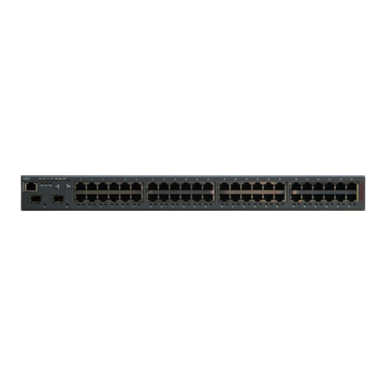
Page 32: C360 Front Panels
C364T-PWR 1 to 48. The two SFP Gigabit Ethernet ports are numbered 51 and Figure 1: C363T Front Panel Figure 2: C363T-PWR Front Panel Figure 3: C364T Front Panel 32 Installation and Configuration Guide Avaya C360 Multilayer Stackable Switches, version 4.5... - Page 33 C360 Front Panels Figure 4: C364T-PWR Front Panel Figure 5: C360 Function LEDs Figure notes: 1. PoE LED on C360-PWR only 2. Left front panel button 3. Right front panel button Issue 2 July 2005...
- Page 34 Blinking - Switch is the stack master and the Octaplane is in redundant cable is active. ROUT Routing Mode OFF - Layer 2 mode ON - Router mode 1 of 3 34 Installation and Configuration Guide Avaya C360 Multilayer Stackable Switches, version 4.5...
- Page 35 C360 Front Panels Table 3: C360 Function LED Descriptions 2 of 3 Description LED Status Name The following Function LEDs apply to all ports Port Status OFF - Port is disabled ON - Link is OK Blinking - Port is enabled, but Link is down...
- Page 36 All LEDs on the switch remain lit until the procedure is complete. Reset the stack Both Right and Left buttons together for five seconds. All LEDs on the stack remain lit until the procedure is complete. 36 Installation and Configuration Guide Avaya C360 Multilayer Stackable Switches, version 4.5...
-
Page 37: C360 Rear Panel
C360 Rear Panel C360 Rear Panel The C360 rear panel contains a stacking module slot, AC power input and BUPS DC input. Note: The C/S: and SW versions on your C360 switches may differ from those shown in Note: Figure... - Page 38 Avaya C360 Front and Rear Panels 38 Installation and Configuration Guide Avaya C360 Multilayer Stackable Switches, version 4.5...
-
Page 39: Chapter 3: Installation
Chapter 3: Installation The C360 switch is ready to work after you complete the installation instructions described in this chapter. After you have completed the procedures in this chapter, proceed to Chapter 4: Powering Up the Avaya C360 The following steps are described in this chapter: Preparing Needed Tools ●... -
Page 40: Site Preparation
Installation Site Preparation You can mount the C360 alone or in a stack in a standard 19-inch equipment rack located in a wiring closet or equipment room. You can build a logical stack of up to ten C360 switches. Ensure that the location where you install your Replace variable w/ short product name fulfills... - Page 41 Site Preparation The power source matches the specifications shown in Table ● Table 7: Power Requirements AC Input voltage 100 to 240 VAC, 50 to 60 Hz Power consumption C363T 60 W ● ● C363T-PWR 420 W ● ● C364T 90 W ●...
-
Page 42: Rack Mounting (Optional)
Before you Install the C360 in a Rack Before you install the C360 in a rack: 1. When installing a C360 in a rack, ensure that the equipment is positioned such that it will not cause the rack to become unstable or tip over. - Page 43 5. Ensure that the internal rack ambient temperature is within the operating specification limits of the C360. 6. Ventilation for the C360 is from side to side. Ensure that there is adequate space on each side of the C360 equipment when installed in the rack to allow sufficient airflow.
-
Page 44: Wall Mounting (Optional)
You must mount the C360 with the ventilation holes facing left and right. CAUTION: You can fix the C360 to the wall as follows: 1. Place the unit on the wall. Ensure that the four C360 screw holes are aligned with the rack hole positions as shown in Figure 10. -
Page 45: Stacking (Optional)
To install the stacking module in the C360: 1. Remove the existing stacking module or blanking plate from the back of the C360 switch. 2. Insert the stacking module gently into the slot, ensuring that the PCB (printed circuit board) is aligned with the guide rails. -
Page 46: Inter-Connecting Switches
Installation Inter-Connecting Switches Tip: You may stack the C360 with the G700, P333T-PWR, P332G-ML or P332GT-ML. Tip: Please refer to Appendix A: Mixed Stacks for further information on mixed stacks. Note: The two ends of the Octaplane cable terminate with different connectors. Each Note: connector can only be connected to its matching port. - Page 47 "right" into the upper port. See Figure Tip: You can build a logical stack of up to ten C360 switches. If you do not wish to Tip: stack all the switches in a single rack, use long Octaplane cables to connect the two physical stacks.
-
Page 48: Making Connections To Network Equipment
Prerequisites Make sure you have the following before attempting to connect network equipment to the C360: A list of network equipment to be connected to the C360, detailing the connector types on ● the various units... -
Page 49: Installing Sfp Gbic Transceivers
4. Check that the appropriate link (LNK) LED lights up. Installing SFP GBIC Transceivers The SFP GBIC (Gigabit Interface Converter) have been tested for use with the C360 Gigabit Ethernet ports. For a list of approved SFP GBIC transceivers, see: http://support.avaya.com... -
Page 50: Installing And Removing A Sfp Gbic Transceiver
Fiber Diameter Modal Maximum Minimum Wavelength Interface Type (µm) Bandwidth Distance Distance (nm) (MhzKm) 1000BASE-SX 62.5 1000BASE-SX 62.5 1000BASE-SX 1000BASE-SX 1000BASE-LX 62.5 1,310 1000BASE-LX 1,310 1 of 2 50 Installation and Configuration Guide Avaya C360 Multilayer Stackable Switches, version 4.5... -
Page 51: Copper Gbic Transceiver Installation Notes
Installing SFP GBIC Transceivers Table 8: Gigabit Fiber Optic Cabling 2 of 2 Gigabit Fiber Diameter Modal Maximum Minimum Wavelength Interface Type (µm) Bandwidth Distance Distance (nm) (MhzKm) 1000BASE-LX 10,000 1,310 1000BASE-ELX 70,000 10,000 1,550 2 of 2 Copper GBIC Transceiver Installation Notes Before installing a copper SFP transceiver, ensure that auto-negotiation is enabled for the transceiver ports. - Page 52 Installation 52 Installation and Configuration Guide Avaya C360 Multilayer Stackable Switches, version 4.5...
-
Page 53: Chapter 4: Powering Up The Avaya C360
Chapter 4: Powering Up the Avaya C360 This chapter describes the procedures for powering up C360 switches. Connecting the C360 to the main electrical supply provides power to the switch and for Power over Ethernet (PoE). WARNING: To isolate the switch completely, you must disconnect all the power connections WARNING: (AC plug and BUPS DC power). -
Page 54: Connecting To An Ac Power Supply
The C360 switch is supplied with a North American power cordset. Below are guidelines that should be used when obtaining and/or defining a different cordset to be used with the C360. The cordsets should be further verified for safety requirements of the particular application by a... -
Page 55: Connecting A Bups
Connecting a BUPS Connecting a BUPS If you deploy a BUPS with the C360, the APC (Advanced Power Conversion PLC) Front End AC-DC Power Shelf (model APC-R2400A111) with APC 800W PSUs (models APC-A0800-085-545-CA1) are to be used.The applied voltage at the C360 BUPS DC terminal block should be from 52 to 55 VDC. -
Page 56: Supplemental Earthing Of The C360 (Optional)
Supplemental Earthing of the C360 (Optional) When connecting a BUPS to the C360, you must also connect a ground wire to the ground stud provided on the rear of the unit. This ground conductor must be green/yellow, a minimum of 16 AWG and be terminated with a lug that is suitable for the M4 stud provided. -
Page 57: Sample Backup Power Supply Scheme
Connecting a BUPS Sample Backup Power Supply Scheme Figure 16 shows a connection example for a stack of three C363T-PWR switches. This configuration provides power supply redundancy and up to 305 W of inline power per C363T-PWR switch. Table 9 lists the equipment required for this scenario. - Page 58 2 of 2 * These items are not available from Avaya. ** You can also use the long Octaplane stacking cables. See the “Avaya X360STK Installation Guide" for information. 58 Installation and Configuration Guide Avaya C360 Multilayer Stackable Switches, version 4.5...
-
Page 59: Budgeting Power
When deciding how many 800W PSUs to install in the APC external DC power shelf, you need to take into account the configuration of the powerinline external power parameter in the C360-PWR switch (set using the set powerinline external power CLI command). Refer to... -
Page 60: Post-Installation
(“Cable to upper unit" or “Cable to lower functioning unit") is lit. page 214 If you do not receive the appropriate indication, please refer to Chapter 12: Troubleshooting the Installation. 60 Installation and Configuration Guide Avaya C360 Multilayer Stackable Switches, version 4.5... -
Page 61: Chapter 5: Establishing Switch Access
Chapter 5: Establishing Switch Access This chapter describes various methods for accessing the C360 CLI and logging in with the appropriate security level: C360 CLI CLI Architecture ● Security Levels ● Entering the CLI ● Establishing Connections Establishing a Console Connection ●... -
Page 62: Cli Architecture
Establishing Switch Access CLI Architecture The C360 stack supports both Layer 2 switching and Layer 3 switching. The C360 CLI includes two CLI entities to support this functionality. The Switch CLI entity is used to manage Layer 2 switching of the entire stack. CLI ●... -
Page 63: Entering The Supervisor Level
Entering the Supervisor Level The Supervisor level is the level in which you first enter C360 CLI and establish user names for up to 10 local users. When you enter the Supervisor level, you are asked for a Login name. -
Page 64: Entering The Cli
This section describes the procedure for establishing switch access between a terminal and the C360 switch over the serial port provided on the front panel of the C360 (RJ-45 connector labeled "Console"). For information on the console port pin assignments, refer to... - Page 65 1. Use the serial cable supplied to attach the RJ-45 console connector to the Console port of the master C360. Connect the DB-9 connector to the serial (COM) port on your PC/terminal. - The master C360 is indicated by the SYS LED being ON.
-
Page 66: Assigning C360 Ip Stack Address
Use the CLI to assign the C360 stack an IP address and net mask. To assign a C360 IP stack address: 1. -
Page 67: Establishing A Telnet Connection
1. Connect your station to the network. 2. Verify that you can communicate with the C360 by pinging the IP of the C360. If there is no response using ping, check the IP address and default gateway of both the C360 and the station. -
Page 68: Establishing An Ssh Connection
3. The client sends to C360 min., max and preferred values for p and the C360 sends client p and g values. In response, the client uses them to derive its DH private key x and its DH... -
Page 69: User Authentication
Establishing an SSH Connection 4. The C360 derives its DH private key y and its DH public key f=(g^y)mod p, and sends the f value to the client, its public host key and the digital signature calculated for all values exchanged so far including f and public host key. -
Page 70: Procedure For Establishing An Ssh Connection
3. Connect your station to the network. 4. Verify that you can communicate with the C360 using Ping to the IP of the C360. If there is no response using Ping, check the IP address and default gateway of both the C360 and the station. -
Page 71: Ssh Commands
(do not use uppercase letters). - The User level prompt will appear when you have established communications with the C360. You can now configure the C360 stack and change its default IP address. SSH Commands The following SSH commands are accessible from Supervisor level. -
Page 72: Establishing Access To Other Entities In The Stack (C360 Sessions)
Establishing Access to Other Entities in the Stack (C360 Sessions) You can use sessions to switch between the CLI of C360 switches, other stack entities, or to switch between Layer 2 and Layer 3 commands. To switch between stack entities use the session [<mod_num>] <mode> CLI command. -
Page 73: Establishing A Modem (Ppp) Connection
4. At the prompt, type: set interface ppp <ip_addr> <net-mask> with an IP address and netmask to be used by the C360 to connect via its PPP interface. Note: The PPP interface configured with the set interface ppp command must be Note: on a different subnet from the stack inband interface. - Page 74 Establishing Switch Access 9. You can now dial into the switch from a remote station, and open a Telnet session to the PPP interface IP address. 74 Installation and Configuration Guide Avaya C360 Multilayer Stackable Switches, version 4.5...
-
Page 75: Snmp Support
SNMP Manager as events occur. Each C360 module has an agent. However, on each C360 stack, one module is selected to be the master module. The stack is managed via the master module's agent. -
Page 76: Snmpv1
In addition, traps are sent to designated trap receivers. Packets with trap information also contains a trap community string. SNMPv2c SNMPv2c is very similar to SNMPv1. However, SNMPv2c adds support for the get-bulk action and supports a different trap format. 76 Installation and Configuration Guide Avaya C360 Multilayer Stackable Switches, version 4.5... -
Page 77: Snmpv3
SNMP Support SNMPv3 SNMPv3 enables the following features over SNMPv1 or v2c: User authentication with a username and password. Authentication is performed using ● md5 or sha-1. Communication encryption between the Network Management Station (NMS) and the ● SNMP agent at the application level Access control definition for specific MIB items available on the SNMP agent ●... -
Page 78: Groups
GroupName - String of up to 32 characters representing the name of the group. ● Security model: ● - SNMPv1 - SNMPv2c - SNMPv3 Security level (for SNMPv3 only): ● - NoAuthNoPriv 78 Installation and Configuration Guide Avaya C360 Multilayer Stackable Switches, version 4.5... -
Page 79: Views
SNMP Support - AuthNoPriv - AuthPriv View names: ● - Read - Allow read-only access to a specified list of Object IDs (OIDs) in the MIB tree. - Write - Allow read-write access to a specified list of OIDs in the MIB tree. - Notify - Allow SNMP notifications from a specified list of OIDs to be sent. - Page 80 SNMPv1 traps sent by the device Removes SNMPv1 trap clear snmp trap receivers Enable or disable SNMPv1 traps set snmp trap enable/disable for authentication failures auth 2 of 3 80 Installation and Configuration Guide Avaya C360 Multilayer Stackable Switches, version 4.5...
- Page 81 SNMP Support Table 16: SNMP CLI Commands 3 of 3 In order to... Use the following command... Enable SNMP notifications snmp-server enable notifications (traps and inform) Disable SNMP notifications no snmp-server notifications (traps and inform) Create an SNMPv3 remote user snmp-server remote-user for SNMP notifications Remove an SNMPv3 remote...
-
Page 82: Radius
(account) information is configured that provides various degrees of access to the switch. The C360 will run as a RADIUS client. When a user attempts to log into the switch, if there is no local user account for the entered user name and password, then the switch will send an Authentication Request to the RADIUS server in an attempt to authenticate the user remotely. - Page 83 RADIUS Figure 19: RADIUS Authentication Procedure User attempts login Lo cal Use r a cco u nt a uth e ntica ted in switch ? Authentication request sent to RAD IU S Server U ser name and password authenticated? Authentication R eject sent to switch Perform log -in according U ser cannot access...
-
Page 84: Radius Commands
For a complete description of the RADIUS CLI commands, including syntax and output examples, refer to the Reference Guide for the Avaya C360 Converged Stackable Switch, 10-300506. 84 Installation and Configuration Guide Avaya C360 Multilayer Stackable Switches, version 4.5... -
Page 85: Recovery Password
Recovery Password Introduction to Recovery Password The C360 provides a recovery password in the event that you have forgotten the login password for the switch. The recovery password feature enables you to login to the device in a super user mode and change the regular login password. -
Page 86: Allowed Managers
Show the IP addresses of the show allowed managers table managers that are allowed to access the device 1 of 2 86 Installation and Configuration Guide Avaya C360 Multilayer Stackable Switches, version 4.5... - Page 87 Allowed Managers Table 19: Allowed Managers CLI Commands 2 of 2 In order to... Use the following command... Show whether the status of show allowed managers status allowed managers is enabled or disabled Show the IP addresses of the show secure current managers that are currently connected 2 of 2...
-
Page 88: Allowed Protocols
Enable SNMP on the switch snmp-server Disable SNMP on the switch no snmp-server Enable SNMPv1 switch access snmp-server community Disable SNMPv1 switch access no snmp-server community 1 of 2 88 Installation and Configuration Guide Avaya C360 Multilayer Stackable Switches, version 4.5... - Page 89 Allowed Protocols Table 20: Allowed Protocol CLI Commands 2 of 2 In order to... Use the following command... Enable SSH on the switch ip ssh enable Disable SSH on the switch no ip ssh Enable Recovery Password on terminal recovery password the switch enable Disable Recovery Password on...
- Page 90 Establishing Switch Access 90 Installation and Configuration Guide Avaya C360 Multilayer Stackable Switches, version 4.5...
-
Page 91: Section 3: Avaya C360 Configuration
Section 3: Avaya C360 Configuration Issue 2 July 2005... - Page 92 92 Installation and Configuration Guide Avaya C360 Multilayer Stackable Switches, version 4.5...
-
Page 93: Chapter 6: Avaya C360 Default Settings
For instructions on the CLI, see the Reference Guide for the Avaya C360 Converged Stackable Switch, 10-300506. For instructions on the use of the graphical user interfaces, refer to the C360 Device Manager User Guide on the Avaya C360 Documentation and Utilities CD. - Page 94 System logging Disabled Allowed protocols: SNMP Enabled Telnet Enabled HTTP Enabled Telnet Enabled ICMP redirect Enabled Disabled Telnet client Disabled Recovery password Enabled User Name/Password root/root 2 of 2 94 Installation and Configuration Guide Avaya C360 Multilayer Stackable Switches, version 4.5...
- Page 95 Configuring the Switch Tip: Functions operate in their default settings unless configured otherwise. Tip: Table 22: Default Port Settings Function Default Setting Ports 1 to 24 Ports 51 and 52 or 1 to 48 Duplex mode Half/Full Full duplex only duplex depending on auto-negotiati...
- Page 96 Avaya C360 Default Settings 96 Installation and Configuration Guide Avaya C360 Multilayer Stackable Switches, version 4.5...
-
Page 97: Chapter 7: Switch Configuration
Use the CLI commands briefly described below for configuring the display on your terminal or workstation.The rules of syntax and output examples are all set out in detail in the Reference Guide for the Avaya C360 Converged Stackable Switch, 10-300506. Table 23: Basic Switch Configuration CLI Commands 1 of 2 In order to... -
Page 98: System Parameter Configuration
System Parameter Configuration Identifying the system In order to make a C360 switch easier to identify, you can define a name for the switch, contact information for the switch technician, and the location of the switch in the organization. The rules of syntax and output examples are all set out in detail in the Reference Guide for the Avaya C360 Converged Stackable Switch, 10-300506. -
Page 99: Operating Parameters
Network Time Acquiring Protocols Parameter Configuration The C360 can acquire the time from a Network Time Server. C360 supports the SNTP Protocol (RFC 958) over UDP port 123 or TIME protocol over UDP port 37. Use the CLI commands briefly described below for configuring and display time information and acquiring parameters. - Page 100 Display the time status and show time parameters parameters Display the current time zone show timezone offset Get the time from the time get time server 2 of 2 100 Installation and Configuration Guide Avaya C360 Multilayer Stackable Switches, version 4.5...
-
Page 101: Uploading And Downloading Device Configurations And Images
Uploading and Downloading Device Configurations and Images The C360 allows you to backup and restore device configurations and configure multiple devices using Simple Network Management Protocol (SNMP) and Trivial File Transfer Protocol (TFTP) or Secure Copy Protocol (SCP) to exchange information with the devices. For more... -
Page 102: Layer 2 Configuration File
CLI commands necessary to configure the device to its current configuration. You can edit the file in a text editor, however, it is recommended that you perform the configuration changes using the C360 Device Manager and/or the CLI. To upload or download Layer 2 configuration files, you must be in a switch mode. -
Page 103: Layer 3 Configuration File
Although the file can be edited, it is recommended to keep changes to the file to a minimum. The recommended configuration method is using C360 Device Manager and/or the CLI. Changes to the configuration file should be limited to those required to customize a configuration file from one router to suit another. - Page 104 Upload a startup configuration copy startup-config tftp file from the device using TFTP Upload the running configuration copy running-config tftp file from the device using TFTP 2 of 2 104 Installation and Configuration Guide Avaya C360 Multilayer Stackable Switches, version 4.5...
-
Page 105: Scp Protocol Support
In addition to data transfer via an SSH session, the SSH protocol is also used to support SCP for secure file transfer. When using SCP, the C360 is the client, and an SCP server must be installed on the management station. After defining users on the SCP server, the device acts as an SCP client. -
Page 106: System Logging
System Logging System Logging Introduction The C360 System Logging feature is capable of storing system messages on a device, outputting messages to the CLI console, Telnet session, or SSH session, and reporting remotely to a Syslog server. System Logging is an important tool used for routine maintenance, auditing, and monitoring access to the device. -
Page 107: Sinks
System Logging Sinks System logging messages can be sent via a number of "sinks" or methods. Table 27 provides a list of available sinks. Table 27: Available Sinks Sink Description Console/ Logging messages are sent to the console or a Telnet or Telnet/SSH SSH session in non- blocking mode. -
Page 108: Syslog Servers
The default access level for Syslog output is "read-write" You can define Message Facility filters to overrule the default threshold. The following is a ● list of default facility thresholds: - Syslog server – Warning 108 Installation and Configuration Guide Avaya C360 Multilayer Stackable Switches, version 4.5... - Page 109 Tip: Use the CLI commands briefly described below for configuring System Logging. The rules of syntax and output examples are all set out in detail in the Reference Guide for the Avaya C360 Converged Stackable Switch, 10-300506. In order to...
- Page 110 CLI console. The output is arranged in descending order of occurrence, with the most recent events first. 2 of 2 110 Installation and Configuration Guide Avaya C360 Multilayer Stackable Switches, version 4.5...
-
Page 111: Telnet Client Support
Telnet Client Support Telnet Client Support Introduction to Telnet The C360 supports invocation of a Telnet client from the CLI. The Telnet client implementation enables you to control the destination port for connecting daemons that listen on a non-default port. -
Page 112: Monitoring Cpu Utilization
Switch Configuration Monitoring CPU Utilization The C360 provides you with the ability to monitor CPU utilization on each module of the stack. Use the CLI commands briefly described below for enabling and disabling CPU utilization monitoring and viewing CPU utilization statistics. The rules of syntax and output examples are all set out in detail in the Reference Guide for the Avaya C360 Converged Stackable Switch, 10-300506. -
Page 113: Chapter 8: Avaya C360 Layer 2 Features
This section describes the C360 Layer 2 features. It provides the basic procedures for configuring the C360 for Layer 2 operation. The C360 supports a range of Layer 2 features. Each feature has CLI commands associated with it. These commands are used to configure, operate, or monitor switch activity for each of the Layer 2 features. -
Page 114: Ethernet
Gigabit Ethernet supports data rates of 1 Gbps. Gigabit Ethernet standards are 1000BASE-T (over copper) or 1000BASE-ELX, 1000BASE-LX and 1000BASE-SX (over fiber). Gigabit Ethernet is standardized as IEEE 802.3z. 114 Installation and Configuration Guide Avaya C360 Multilayer Stackable Switches, version 4.5... -
Page 115: Configuring Ethernet Parameters
Ethernet Figure 20: maximum Ethernet Cable Lengths 1000 BASE-ELX 9µ Single-mode 1550 nm 9µ Single-mode 1000 BASE-LX 1300 nm 50µ Multi-mode 62.5µ Multi-mode 50µ Multi-mode 1000 BASE-SX 850 nm 62.5µ Multi-mode 9µ Single-mode 10/100BASE-FX 1000 BASE-T 10/100BASE-T 100 m 275 m 550 m 2 km 5 km... -
Page 116: Mdi/Mdi-X Detection
Priority determines in which order packets are sent on the network and is a key part of QoS (Quality of Service). The IEEE standard for priority on Ethernet networks is 802.1p. The C360 supports four internal priority queues and the classification of packets within the queues is as follows:... -
Page 117: Mac Address
The MAC Aging feature allows the user to configure a time interval after which unused entries in the MAC Table will be deleted. Following is the description of configuration of the C360 for the MAC Aging functionality. MAC Aging is configured on the stack level. -
Page 118: Ethernet Configuration Cli Commands
Display per-port status show port flowcontrol information related to flow control Display the flow control show port advertisement for a Gigabit port auto-negotiation-flowcontrol-advertisement used to perform auto-negotiation 1 of 2 118 Installation and Configuration Guide Avaya C360 Multilayer Stackable Switches, version 4.5... - Page 119 Ethernet Table 30: Ethernet Configuration CLI Commands 2 of 2 In order to... Use the following command... Display the CAM table entries show cam for a specific port Display the CAM table entries show cam mac for a specific MAC address Clear all the CAM table entries.
-
Page 120: Vlans
LAN-such as in different departments, on different floors or in different buildings. Connections are made through software. Each network device is connected to a hub, and the network 120 Installation and Configuration Guide Avaya C360 Multilayer Stackable Switches, version 4.5... -
Page 121: Vlan Tagging
VLANs manager uses management software to assign each device to a virtual topological network. Elements can be combined into a VLAN even if they are connected to different devices. VLANs should be used whenever there are one or more groups of network users that you want to separate from the rest of the network. -
Page 122: Multi Vlan Binding
VLAN for privacy, but the whole building has a shared high-speed connection to the ISP. In order to accomplish this, C360 allows you to set multiple VLANs per port. The three available Port Multi-VLAN binding modes are: Bind to All - the port is programmed to support the entire 3K VLANs range. -
Page 123: Ingress Vlan Security
VLANs Figure 23: Multiple VLAN Per-port Binding Modes Figure notes: 1. Bind to All - Any VLAN in the range of 1 to 3,071 will be allowed access through this port - Intended mainly for easy backbone link 2. Static Binding - You manually specify the list of VLAN IDs to be bound to the port, up to 3,071 VLANs - Default mode for every port - Only VLAN 9, and any other VLANs statically configured on the port will be allowed to... -
Page 124: Vlan Cli Commands
VLAN CLI Commands The following table contains a list of the CLI commands for the VLAN feature. The rules of syntax and output examples are all set out in detail in the Reference Guide for the Avaya C360 Converged Stackable Switch, 10-300506. - Page 125 VLANs Table 32: VLAN CLI Commands 2 of 2 In order to... Use the following command... Clear a VLAN statically clear port static-vlan configured on a port Clear the dynamic vlans learned clear dynamic vlans by the switch from incoming traffic Display the MAC addresses show cam vlan...
-
Page 126: Ieee 802.1X (Port Based Network Access Control)
● "unauthorized" which closes the port to any traffic. As a result of an authentication attempt, the C360 port can be either in a "blocked" or a ● "forwarding" state. -
Page 127: Ieee 802.1X Implementation In The C360
C360 line: You can configure 802.1x on the 10/100 Mbps Ethernet ports only. ● 802.1x can work only if a RADIUS server is configured on the C360 and the RADIUS ● server is carefully configured to support 802.1x. 802.1x and port/intermodule redundancy can co-exist on the same ports. -
Page 128: 802.1X Cli Commands
802.1x CLI Commands The following table contains a list of the CLI commands for the 802.1x feature. The rules of syntax and output examples are all set out in detail in the Reference Guide for the Avaya C360 Converged Stackable Switch, 10-300506. - Page 129 IEEE 802.1x (Port Based Network Access Control) In order to... Use the following command... Set the server retransmission set dot1x server-timeout timeout period for all ports Set the authentication period (an set dot1x re-authperiod idle time between re-authentication attempts) Set the set dot1x supp-timeout authenticator-to-supplicant retransmission timeout period...
- Page 130 Set the max-req per port (the set port dot1x max-req maximal number of times the port tries to retransmit requests to the Authenticated Station before the session is terminated) 3 of 3 130 Installation and Configuration Guide Avaya C360 Multilayer Stackable Switches, version 4.5...
-
Page 131: Spanning Tree Protocol
Spanning Tree Protocol Overview C360 switches support both common Spanning Tree protocol (802.1d) and the enhanced Rapid Spanning Tree protocol (802.1w). IEEE 802.1w is a faster and more sophisticated version of the 802.1d (STP) standard. Spanning Tree makes it possible to recover connectivity after an outage within a minute or so. -
Page 132: Spanning Tree Per Port
Whereas the STA passively waited for the network to converge before turning a port into the forwarding state, RSTP actively confirms that a port can safely transition to forwarding without relying on any specific, programmed timer configuration. 132 Installation and Configuration Guide Avaya C360 Multilayer Stackable Switches, version 4.5... -
Page 133: Spanning Tree Implementation In The C360
- is sufficient for most networks. Spanning Tree Implementation in the C360 RSTP is implemented in C360 family of products so that it is interoperable with the existing implementation of STP. In order to configure the switch to either common Spanning Tree or Rapid Spanning Tree protocol, use the set spantree version command. -
Page 134: Spanning Tree Protocol Cli Commands
Spanning Tree Protocol CLI Commands The following table contains a list of CLI commands for the Spanning Tree feature. The rules of syntax and output examples are all set out in detail in the Reference Guide for the Avaya C360 Converged Stackable Switch, 10-300506. - Page 135 Spanning Tree Protocol In order to... Use the following command... Remove a port from the spanning set port spantree disable tree application Set the port spantree priority set port spantree priority level Set the cost of a port set port spantree cost Set the port as an RSTP port set port spantree (and not as a common STA port)
-
Page 136: Mac Security
MAC Address Table. If either the source MAC address is not found there, or it is found but with a different ingress port location, then the frame is rejected The C360 can be configured to take one of the following actions when an attempted intrusion occurs: Drop –... -
Page 137: Mac Security Cli Commands
MAC Security CLI Commands The following table contains a list of CLI commands for the MAC Security feature. The rules of syntax and output examples are all set out in detail in the Reference Guide for the Avaya C360 Converged Stackable Switch, 10-300506. -
Page 138: Lag (Link Aggregate Group)
LAG CLI Commands The following table contains a list of the CLI commands for the LAG feature. The rules of syntax and output examples are all set out in detail in the Reference Guide for the Avaya C360 Converged Stackable Switch, 10-300506. -
Page 139: Lag Implementation In The C360
10/100BASE-T ports numbered 1-24 and 25-48 in a LAG within their respective ports groups, 1-24 or 25-48. The relationship between the C360 Port Numbers and the LAG logical Port Number that will be assigned to each LAG is shown in... -
Page 140: Port Redundancy
In addition to Link Aggregation Groups - which comprise the basic redundancy mechanism within the switch - the C360 offers an additional port redundancy scheme. To achieve port redundancy, you can define a redundancy relationship between any two ports in a stack. One port is defined as the primary port and the other as the secondary port. -
Page 141: Intermodule Port Redundancy
Port Redundancy - "switchback-interval" - the minimum time (in seconds) that the primary port link has to be up (following failure) before the system switches back to the primary port. If you set this to zero, there is no switch back. Intermodule Port Redundancy The intermodule port redundancy feature supports one pair of redundant ports per stack. -
Page 142: Port Redundancy Cli Commands
Port Redundancy CLI Commands The following table contains a list of the CLI commands for the Redundancy feature. The rules of syntax and output examples are all set out in detail in the Reference Guide for the Avaya C360 Converged Stackable Switch, 10-300506. -
Page 143: Port Classification
Port Classification Overview With the C360, you can classify any port as regular or valuable. Setting a port to valuable means that, in case of Ethernet link failure of that port, a link fault trap can be sent even when the port is disabled. -
Page 144: Ip Multicast Filtering
This learning is based on IGMP (version 1 or 2) snooping. The multicast filtering function in the C360 is transparent to the IP hosts and routers. It does not affect the forwarding behavior apart from filtering multicast packets from certain ports where they are not needed. - Page 145 The Router Port Pruning timer ages out Router port information if IGMP queries are not ● received within the configured time. The Client Port Pruning time is the time after the C360 switch reset that the filtering ● information is learned by the switch but not configured on the ports.
-
Page 146: Ip Multicast Cli Commands
The following table contains a list of the CLI commands for the IP Multicast feature. The rules of syntax and output examples are all set out in detail in the Reference Guide for the Avaya C360 Converged Stackable Switch, 10-300506. -
Page 147: Rmon
RMON RMON RMON Overview RMON, the internationally recognized network monitoring standard, is a network management protocol that allows network information to be gathered at a single workstation. You can use RMON probes to monitor and analyze a single segment only. When you deploy a switch on the network, there are additional components in the network that cannot be monitored using RMON. - Page 148 Display the parameters of an show rmon event Event entry defined by the rmon event command or Device Manager Clears all RMON counters in the clear rmon statistics stack 2 of 2 148 Installation and Configuration Guide Avaya C360 Multilayer Stackable Switches, version 4.5...
-
Page 149: Smon
● Network view for selected ports ● VLAN view ● History ● Tip: In order to use SMON, you need to install the SMON license on the C360 switch Tip: and use Avaya IM with SMON Issue 2 July 2005... -
Page 150: Smon Cli Commands
Avaya C360 Layer 2 Features Note: SMON for the network layer is not supported in this version of the C360. Note: SMON CLI Commands In order to... Use the following command... Enter the SMON license set license Display licenses installed on the... -
Page 151: Port Mirroring
You can define one source port and one destination port on each C360 stack for either received - Rx - or transmitted and received - Tx + Rx - traffic. -
Page 152: Weighted Queuing
"Strict Priority" or to configure it as a Weighted Round Robin (WRR) scheme, with user-configurable weights. Tip: If the queuing scheme commands are to be implemented on a C360 switch other Tip: than the stack master, a session should be opened to the relevant switch. -
Page 153: Lldp Agent
LLDP Agent LLDP Agent LLDP Agent Overview IEEE 802.1AB Link Layer Discovery Protocol (LLDP) simplifies troubleshooting of enterprise networks and enhances the ability of network management tools to discover and maintain accurate network topologies in multi-vendor environments. It defines a set of advertisement messages, called TLVs, a protocol for transmitting and receiving the advertisements, and a method for storing the information contained in the received advertisements. -
Page 154: Configuring The Lldp Agent
1. Enable the LLDP agent globally using the set lldp system-control command. C360-1 (super)# set lldp system-control enable Done! This command affects all C360 switches within a stack and activates TLV reception and mandatory TLV transmission on all stack ports according to the administrative LLDP port status (refer to step 2). -
Page 155: Lldp Agent Cli Commands
The following table contains a list of the CLI commands for the LLDP Agent feature. The rules of syntax and output examples are all set out in detail in the Reference Guide for the Avaya C360 Converged Stackable Switch, 10-300506. - Page 156 Avaya C360 Layer 2 Features 156 Installation and Configuration Guide Avaya C360 Multilayer Stackable Switches, version 4.5...
-
Page 157: Chapter 9: Avaya C360 Layer 3 Features
IP Fragmentation and Reassembly ● Layer 3 features only apply to the C360 operating in router mode. You must purchase a Routing License Key Certificate for the C360 and activate the feature in order to operate in router mode. Refer to Obtaining and Activating a License Key on page 158 for further information. -
Page 158: Obtaining And Activating A License Key
The switch type. ● The required feature. ● The number of devices. ● After you purchase a Routing Licence Key Certificate, you must obtain and activate a Routing License Key. 158 Installation and Configuration Guide Avaya C360 Multilayer Stackable Switches, version 4.5... -
Page 159: Obtaining A Routing License Key
Obtaining and Activating a License Key Obtaining a Routing License Key To obtain a License Key that enables routing features: 1. Go to http://license-lsg.avaya.com and click "request new license". Issue 2 July 2005... - Page 160 Avaya C360 Layer 3 Features 2. Enter the Certificate Key and Certificate Type. 3. Click Next. 160 Installation and Configuration Guide Avaya C360 Multilayer Stackable Switches, version 4.5...
- Page 161 Obtaining and Activating a License Key 4. Enter contact information (once per certificate) 5. Click Next. Issue 2 July 2005...
- Page 162 Avaya C360 Layer 3 Features 6. View number of licenses left. 162 Installation and Configuration Guide Avaya C360 Multilayer Stackable Switches, version 4.5...
- Page 163 Obtaining and Activating a License Key 7. Enter serial number of the switch(es) or module. To identify serial numbers use the CLI command: show module-identity. Issue 2 July 2005...
- Page 164 Avaya C360 Layer 3 Features 8. Click Generate. The feature-enabling license code is generated 164 Installation and Configuration Guide Avaya C360 Multilayer Stackable Switches, version 4.5...
-
Page 165: Activating A Routing License Key
Obtaining and Activating a License Key Activating a Routing License Key To activate a Routing License Key: 1. Enter the acquired Routing License Key into the C360 switch using the set license CLI CLI command. set license [module] [license] [featureName]... -
Page 166: What Is Routing
As the packet moves through the internetwork, its physical address changes but its protocol address remains constant. This process is illustrated in the figure below. 166 Installation and Configuration Guide Avaya C360 Multilayer Stackable Switches, version 4.5... - Page 167 What is Routing? Figure 26: Routing Figure notes: 1. First Hop: Protocol address: Destination ● Physical address: Router 1 ● 2. Second Hop: Protocol address: Destination ● Physical address: Router 2 ● The relation between the destination host's protocol address and its physical address is obtained by the routers using the ARP request/reply mechanism, and the information is stored within the ARP table in the router (see The ARP Table...
-
Page 168: Routing Configuration
Routing Configuration Forwarding The C360 forwards IP packets between IP networks. When it receives an IP packet through one of its interfaces, it forwards the packet through one of its interfaces. The C360 supports multinetting, enabling it to forward packets between IP subnets on the same VLAN as well as between different VLANs. -
Page 169: Ip Configuration
IP Configuration IP Configuration IP Configuration CLI Commands In order to... Use the following command... Enable IP routing ip routing Set ICMP error messages ip icmp-errors Specify the format of netmasks ip netmask-format in the show command output Create and/or enter the interface Interface Configuration Mode Assign an IP address and mask... -
Page 170: Assigning Initial Router Parameters
<module number> router where <module number> is the location of the router module in the stack, and press Enter. The command prompt changes from C360-N> to Router-N#> where N is the number of the router in the stack (see SNMP Support). - Page 171 IP Configuration Tip: If the IP interface is on VLAN #1, continue with Step 7. Tip: 6. Create the management/routing VLAN. Use the command set vlan <Vlan-id> name <Vlan-name> replacing <Vlan-id> by the VLAN number, and <Vlan-name> by the VLAN name. Press Enter. 7.
-
Page 172: Rip (Routing Interchange Protocol) Configuration
The very simplicity of RIP has a disadvantage, however: it does not take into account the network bandwidth, physical cost, data priority, and so on. The C360 supports the widely used RIP routing protocol (both RIPv1 and RIPv2). The RIPv1 protocol imposes some limitations on the network design with regard to subnetting. When operating RIPv1, you must not configure variable length subnet masks (VLMS). -
Page 173: Rip2
RIP (Routing Interchange Protocol) Configuration RIP2 RIP2 overcomes some of the shortcomings of RIP. The table below summarizes the differences between RIP and RIP2. Table 34: DIfferences Between RIP and RIP2 RIP2 Multicast addressing Broadcast Addressing Event-driven Timer-based (update every 30 seconds) VLSM support (subnet information transmitted) Fixed subnet masks RIP CLI Commands... - Page 174 RIP Version 2 packets Set the authentication string ip rip authentication key used on the interface Specify the RIP timers values timers basic 2 of 2 174 Installation and Configuration Guide Avaya C360 Multilayer Stackable Switches, version 4.5...
-
Page 175: Ospf (Open Shortest Path First) Configuration
(topography). The C360 supports the OSPF routing protocol. The C360 can serve as an OSPF Autonomous System Boundary Router (ASBR) by configuration of route redistribution. The C360 can be installed in the OSPF backbone area (area 0.0.0.0) or in any OSPF area that is part of a multiple... -
Page 176: Ospf Cli Commands
Display lists of information show ip ospf database related to the OSPF database for a specific router Configure an interface as passive-interface passive 176 Installation and Configuration Guide Avaya C360 Multilayer Stackable Switches, version 4.5... -
Page 177: Static Routing Configuration
The next hop router must belong to one of the directly attached networks for which the C360 has an IP interface. "Local" static routes, such as those that have no next hop, are not allowed. -
Page 178: Static Routing Configuration Cli Commands
The preferences only apply to routes for the same destination IP address and mask. They do not override the longest-match choice. For example, a high-preference static default route will not be preferred over a RIP route to the subnet of the destination. 178 Installation and Configuration Guide Avaya C360 Multilayer Stackable Switches, version 4.5... - Page 179 Static Routing Configuration C360 protocol preferences are listed below from the most to the least preferred: 1. Local (directly attached net) 2. High-preference static (manually configured routes) 3. OSPF internal routes 4. RIP 5. OSPF external routes 6. Low-preference static (manually configured routes).
-
Page 180: Route Redistribution
By default, static routes are not redistributed to RIP and OSPF. The C360 allows the user to globally enable redistribution of static routes to RIP, and separately, to globally enable redistribution of static routes to OSPF. In addition, the C360 lets the user configure, on a per static route basis, whether the route is to be redistributed to RIP and OSPF, and what metric (in the range of 1-15). -
Page 181: Arp (Address Resolution Protocol) Table Configuration
ARP (Address Resolution Protocol) Table Configuration ARP (Address Resolution Protocol) Table Configuration ARP Overview IP logical network addresses are independent of physical addresses. Since the physical address must be used to convey data in the form of a frame from one device to another, a mechanism is required to acquire a destination device hardware address from its IP address. -
Page 182: The Arp Table
ARP cache and the IP route cache Display the Address Resolution show ip arp Protocol (ARP) cache Display the IP address of a host, show ip reverse-arp based on a known MAC address 182 Installation and Configuration Guide Avaya C360 Multilayer Stackable Switches, version 4.5... -
Page 183: Bootp/Dhcp (Dynamic Host Configuration Protocol) Relay Configuration
Note that the same DHCP/BOOTP relay agent serves both the BOOTP and DHCP protocols. When there is more than one IP interface on a VLAN, the C360 automatically chooses one of the IP interface's to determine the relay network. Alternatively, you can configure the relay networks that the C360 will use. -
Page 184: Bootp/Dhcp Cli Commands
C360. DHCP/BOOTP Relay in C360 is configurable per VLAN and allows you to specify two DHCP/ BOOTP servers. In this case, it duplicates each request, and sends it to both servers. This provides redundancy and prevents the failure of a single server from blocking hosts from loading. -
Page 185: Netbios Re-Broadcast Configuration
LANs for PCs are based on the NetBIOS. Some LAN manufacturers have even extended it, adding additional network capabilities. You can configure the C360 to relay netbios UDP broadcast packets. This feature is used for applications such as WINS that use broadcast but may need to communicate with stations on other subnets or VLANs. -
Page 186: Vrrp (Virtual Router Redundancy Protocol) Configuration
VRRP can be activated on an interface using a single command while allowing for the necessary fine-tuning of the many VRRP parameters. For a detailed description of VRRP, refer to VRRP standards and published literature. 186 Installation and Configuration Guide Avaya C360 Multilayer Stackable Switches, version 4.5... -
Page 187: Vrrp Configuration Example 1
● This configuration must be done per VLAN). The C360 requires that this VRID must not be used in the network (even in different VLAN) ● By the end of the routers configuration, and when the network is up, the main router for ●... -
Page 188: Case #2
(in seconds) for the virtual router ID Set the virtual router priority ip vrrp priority value used when selecting a master route 1 of 2 188 Installation and Configuration Guide Avaya C360 Multilayer Stackable Switches, version 4.5... - Page 189 VRRP (Virtual Router Redundancy Protocol) Configuration In order to... Use the following command... Set or disable the virtual router ip vrrp auth-key simple password authentication for the virtual router ID. Configure or disable the router ip vrrp preempt to preempt a lower priority master for the virtual router ID Set the primary address that ip vrrp primary...
-
Page 190: Policy Configuration
Using the ACK bit of the TCP header. ● The C360 uses policy lists containing both Access Control rules and QoS rules. The policy lists are ordered by rule indexing. Tip: Use the Command Line Interface and the Avaya central policy management... -
Page 191: Policy Configuration Cli Commands
Policy Configuration Policy Configuration CLI Commands In order to... Use the following command... Set the default action for a given ip access-default-action Policy List. Create an access-list rule in a ip access-list specific Access List. Set the source list, destination ip access-list-copy list, and destination module for copying an entire Policy List... -
Page 192: Policy Configuration Example
1. Voice packet 5. Access Control 2. Data packet 6. QoS 3. Unauthorized packet 7. Packet dropped 4. Policy Rules 8. Four egress queues (Highest, High, Normal, Low) 192 Installation and Configuration Guide Avaya C360 Multilayer Stackable Switches, version 4.5... -
Page 193: Policy Configuration Example
0.0.255.255 any done! 2. Assigning priority 3 to all TCP traffic going to the host 172.44.17.1 - rule 2: C360-1(super)# ip access-list 100 2 fwd3 tcp any host 172.44.17.1 done! 3. Denying Telnet sessions originated by the host 192.168.5.33 - rule 3: C360-1(super)# ip access-list 100 3 deny tcp host 192.168.5.33... -
Page 194: Ip Fragmentation And Reassembly
Avaya C360 Layer 3 Features IP Fragmentation and Reassembly IP Fragmentation and Reassembly Overview The C360 supports IP Fragmentation and Reassembly. This feature allows the router to send and receive large IP packets where the underlying data link protocol constrains MTU (maximum transport unit). - Page 195 IP Fragmentation and Reassembly In order to... Use the following command... Set the maximum number of fragment timeout seconds to reassemble a fragmented IP packet destined for the router. Display information regarding show fragment fragmented IP packets that are destined for the router 2 of 2 Issue 2 July 2005...
- Page 196 Avaya C360 Layer 3 Features 196 Installation and Configuration Guide Avaya C360 Multilayer Stackable Switches, version 4.5...
-
Page 197: Chapter 10: Avaya C360 Power Over Ethernet Features
Chapter 10: Avaya C360 Power over Ethernet Features This chapter describes the C360-PWR PoE (Power over Ethernet Features). It provides the basic procedures for configuring the C360 for PoE operation. It contains the following sections: Load Detection ● “Plug and Play" Operation ●... -
Page 198: Power Over Ethernet
The C360-PWR switches periodically check all ports, powered and non-powered to check their status and the power status of connected devices. The C360-PWR switches will supply power to a port only after it has detected a suitable PD (powered device) is connected to the port. The check consists of the C360-PWR switches looking for a signature from the device that indicates it needs to supply power. -
Page 199: Specific Resistance Signature (Ieee 802.3Af)
Specific Resistance Signature (IEEE 802.3af) The C360-PWR switches apply a low voltage to the power feed pairs and measures the current. A resistance of 19kΩ to 26.5kΩ is considered valid according to the IEEE standard; if a valid signature is detected, power is supplied to the port. -
Page 200: Powering Devices
Powering Devices The C360 ports can receive Inline power from one of two sources: an internal -48VDC power supply or an external DC power supply. Each port can supply up to 15.4W by default to the powered device. -
Page 201: Power Over Ethernet In Converged Networks
IP telephones, wireless network access devices and Web cameras. Figure 31: Powered Ethernet Application Both the data and power paths from the C360-PWR to the PBX are backed-up. Using LAGs for data with UPSs (Uninterruptible Power Supplies) for power ensures non-stop IP communications. -
Page 202: Power Over Ethernet Cli Commands
PoE port. set powerinline trap Configure PoE traps and the consumption usage threshold value. show powerinline Show the current status of the PD inline power on all ports 202 Installation and Configuration Guide Avaya C360 Multilayer Stackable Switches, version 4.5... -
Page 203: Chapter 11: C360 Device Manager
● Port Redundancy - Setting port redundancy for ports in a C360 Switch. ● Port Mirroring - Setting up port mirroring for ports in a C360 Switch. ● Trap Managers Configuration - Viewing and modifying the Trap Managers Table. ●... -
Page 204: System Requirements
Set the location of the Web set web aux-files-url server with the help files and the Java plug-in Display the SNMP retries show snmp retries parameter 204 Installation and Configuration Guide Avaya C360 Multilayer Stackable Switches, version 4.5... -
Page 205: Running The Device Manager
1. Open your browser. 2. Point your web browser to http://xxx.xxx.xxx.xxx, where xxx.xxx.xxx.xxx is the IP address of the Avaya C360 Device you want to manage. The SNMP parameters dialog box opens: Figure 32: SNMP parameters dialog box 3. For SNMPv1 login a. - Page 206 - Click Yes - If the required Java plug-in is not installed, the plug-in is automatically downloaded to your computer. Follow the instructions on the Avaya C360 Welcome page to install the plug-in. 5. \The welcome page is displayed. See Figure 34 206 Installation and Configuration Guide Avaya C360 Multilayer Stackable Switches, version 4.5...
- Page 207 Running the Device Manager Figure 34: The Welcome Page 6. If you have the Java plug-in installed, the Device Manager should open in a new window (see Figure 35). Figure 35: Device Manager Issue 1 June 2005...
-
Page 208: Installing The Java Plug-In
To install from the C360 documentation and Utilities CD: 1. Close all unnecessary applications on your PC. 2. Insert the Avaya C360 Documentation and Utilities CD in the CD drive. 3. Open Windows Explorer. 4. Open the embweb-aux-files\ folder on the CD 5. -
Page 209: Installing The On-Line Help And Java Plug-In On Your Web Site
Embedded Manager and enables automatic Installation and Maintenance of the Java plug-in the first time the users tries to manage the device. 1. Copy the emweb-aux-files directory from the Avaya C360 Documentation and Utilities CD to your local Web server. Please refer to your Web server documentation for full instructions. - Page 210 C360 Device Manager 210 Installation and Configuration Guide Avaya C360 Multilayer Stackable Switches, version 4.5...
-
Page 211: Section 4: Troubleshooting And Maintaining The Avaya C360
Section 4: Troubleshooting and Maintaining the Avaya C360 Issue 2 July 2005... - Page 212 212 Installation and Configuration Guide Avaya C360 Multilayer Stackable Switches, version 4.5...
-
Page 213: Chapter 12: Troubleshooting The Installation
Troubleshooting the Installation This section will allow you to perform basic troubleshooting of the installation. If you are unable to solve the problem after following the procedures in this chapter, please contact Avaya Technical Support. Table 35: Troubleshooting 1 of 3... - Page 214 216 for further information. X360-STK modules Check that modules are installed ● ● not inserted correctly correctly (LEDs on stacking module do not light) 2 of 3 214 Installation and Configuration Guide Avaya C360 Multilayer Stackable Switches, version 4.5...
- Page 215 Troubleshooting the Installation Table 35: Troubleshooting 3 of 3 Problem/Cause Suggested Solution Octaplane cables not Check that the cables are ● ● installed correctly inserted correctly (LEDs on stacking Check that there are no ● module do not light) cross-corrections The pins on the Replace the cable ●...
-
Page 216: Stack Health
Troubleshooting the Installation Stack Health The C360 software provides a Stack Health feature for verifying the integrity of the C360 and P330 and P330-ML stacking module and cables. Overview The Stack Health feature will identify defective modules and cables that may be installed in the C360 stack. -
Page 217: Stack Health Cli Commands
Stack Health CLI Commands The following table contains a list of the CLI commands for the Stack Health feature. The syntax and output examples are set out in detail in the Reference Guide for the Avaya C360 Converged Stackable Switch, 10-300506. - Page 218 Troubleshooting the Installation 218 Installation and Configuration Guide Avaya C360 Multilayer Stackable Switches, version 4.5...
-
Page 219: Chapter 13: Maintenance
4. Insert the new stacking module gently into the slot, ensuring that the PCB (printed circuit board) is aligned with the guide rails. 5. Press the stacking module in firmly until it is completely inserted into the C360. CAUTION: Ensure that the screws on the module are properly aligned with the holes in the CAUTION: chassis before tightening them. -
Page 220: Hardware Nvram Initialization
Touching the circuit boards unless instructed to do so may damage them. PRECAUCIÓN: El switch C360 y sus módulos de ampliación contienen componentes sensibles a PRECAUCION: descargas electrostáticas. Tocar las tarjetas sin autorización del personal técnico puede dañarlas. - Page 221 Figure 36: Location of the NVRAM INIT Jumpers Figure notes: 1. SPARE JUMPER 2. NVRAM INIT Jumper 3. Insert the X360STK module into the C360 switch where you wish to perform the NVRAM initialization. Refer to Installing the X360STK Stacking Module for further information.
- Page 222 Maintenance 222 Installation and Configuration Guide Avaya C360 Multilayer Stackable Switches, version 4.5...
-
Page 223: Chapter 14: Updating The Firmware
You can perform firmware download using the CLI or Avaya Software Update Manager (part of the Avaya Integrated Management Suite). Obtain Software Online You can obtain the firmware and C360 Device Manager from the "Downloads" section on the Avaya Support Site at http://support.avaya.com. Downloading Firmware... -
Page 224: Download New Version Without Overwriting Existing Version
Version Firmware Banks The C360 has two firmware banks, Bank A and Bank B that contain the firmware necessary to run the switch. Each bank is independent of the other and you may use them to store the same or different versions of the firmware. -
Page 225: Appendix A: Mixed Stacks
Appendix A: Mixed Stacks This appendix covers deployment of the C360 in mixed stack environments. Please refer to the relevant section for information. Tip: For additional information, see the Release Notes or the Avaya Support site: Tip: http://support.avaya.com. You may stack the C360 with P333T-PWR, P332G-ML and P332GT-ML switches and G700 Media Gateway, subject to certain limitations which are described in this appendix. -
Page 226: Hardware Compatibility
This section describes hardware compatibility issues. Stacking Tip: It is recommended to put the C360 switches at the bottom or top of a mixed stack Tip: for easier connection of cables. You may use the same Octaplane cables for stacking all the switches. However, the stacking modules are not interchangeable. -
Page 227: Bups
The Backup Power Supplies are not interchangeable. Please refer to Table 38 for information on which stacking module to use. Table 38: BUPS Compatibility Switch BUPS C360 APC-800 (refer to Connecting a BUPS on page 55 for further information) G700... -
Page 228: Feature Compatibility
Traps generated by the P333T-PWR and G700 are sent via SMPv1 only. LLDP C360 ports only. 802.1x 10/100 Mbps ports only. Queues are mapped. Queues Refer to Mapping. 1 of 2 228 Installation and Configuration Guide Avaya C360 Multilayer Stackable Switches, version 4.5... -
Page 229: Qos Mapping
Certain CLI commands apply to the C360 only. If you run them on other switches Note: you may receive an "operation failed" message. QoS Mapping The four C360 QoS queues are mapped to the two QoS queues in the G700, P333T-PWR, P332G-ML and P332GT-ML as follows: Table 40: QoS Mapping C360 Priority... - Page 230 Mixed Stacks 230 Installation and Configuration Guide Avaya C360 Multilayer Stackable Switches, version 4.5...
-
Page 231: Appendix B: Configuring C360 Qos For Avaya Ip Telephones
Appendix B: Configuring C360 QoS for Avaya IP Telephones Introduction This appendix covers configuring C360 QoS settings for Avaya IP Telephony environments. Table 41: Configuration for ports connected to Avaya IP Telephones Parameter Value CLI command PVID Data VLAN set port vlan <vlan_num>... - Page 232 Configuring C360 QoS for Avaya IP Telephones 232 Installation and Configuration Guide Avaya C360 Multilayer Stackable Switches, version 4.5...
-
Page 233: Appendix C: Standards And Compatibility
Appendix C: Standards and Compatibility Avaya C360 Standards Supported The Avaya C360 complies with the following standards. IEEE 802.1D Bridges and STA ● 802.1p Priority Tagging on all ports ● 802.1Q VLAN Tagging support on all ports ● 802.1w Rapid Spanning Tree ●... -
Page 234: Ietf - Layer 3
RFC 1812- Requirements for IP Version 4 Routers ● RFC 1850 -OSPF Version 2 Management Information Base ● RFC 2096 - IP Forwarding Table MIB ● RFC 2338 - Virtual Router Redundancy Protocol ● 234 Installation and Configuration Guide Avaya C360 Multilayer Stackable Switches, version 4.5... -
Page 235: Ietf - Network Monitoring
IETF - Network Monitoring IETF - Network Monitoring RMON (RFC 1757) support for groups 1,2,3, and 9 ● - Statistics - History - Alarms - Events SMON (RFC 2613) support for groups ● - Data Source Capabilities - Port Copy - VLAN and Priority Statistics Bridge MIB Groups - RFC 2674 ●... - Page 236 Standards and Compatibility 236 Installation and Configuration Guide Avaya C360 Multilayer Stackable Switches, version 4.5...
-
Page 237: Appendix D: Specifications
Appendix D: Specifications Physical Height 1U (44.45 mm, 1.75”) Width 431 mm (17”) Depth 365 mm (14.4”) Weight C363T 4.9 kg (10.8 lb.) ● C363T-PWR 5.5 kg (12.1 lb.) ● C364T 5.0 kg (11 lb.) ● C364T-PWR 6.8 kg (15 lb.) ●... -
Page 238: Environmental
- FDA CFR 1040 for USA Branch Circuit Protection: A UL Listed and CSA Certified 15A branch circuit protective ● device is to be provided in the building AC mains wiring installation. 238 Installation and Configuration Guide Avaya C360 Multilayer Stackable Switches, version 4.5... -
Page 239: Mtbf
MTBF MTBF Product MTBF (Hours) C363T 300,000 C364T 210,000 C363T-PWR 245,000 C364T-PWR 170,000 Interfaces C363T: 24 x 10/100 BASE-T RJ-45 port connectors + 2 x SFP GBIC connectors. ● C363T-PWR: 24 x 10/100 PoE BASE-T RJ-45 port connectors + 2 x SFP GBIC ●... -
Page 240: Sx Transceiver
1000BASE-T SFP GBIC port. The cable length can be a maximum of 100 m (328 ft.). Tip: The copper ports operate at 1000 Mbps full-duplex only. Tip: 240 Installation and Configuration Guide Avaya C360 Multilayer Stackable Switches, version 4.5... -
Page 241: Console Pin Assignments
Console Pin Assignments Console Pin Assignments For direct Console communications, connect the C360 to the Console Terminal using the supplied RJ-45 crossed cable and RJ-45 to DB-9 adapter. C360 RJ-45 Pin Name Terminal Modem (DCE View) DB-9 Pins DB-25 Pins... -
Page 242: Ethernet
Specifications Ethernet VLANs ● - Layer 23,071 - Layer 3255 MAC addressesminimum 16k ● Priority queuing4 queues ● Multicast groups1k ● 242 Installation and Configuration Guide Avaya C360 Multilayer Stackable Switches, version 4.5... -
Page 243: Index
IP to switch ... . for Avaya IP Telephones ....entering in switch Connecting . - Page 244 ........MAC aging specifications 244 Installation and Configuration Guide Avaya C360 Multilayer Stackable Switches, version 4.5...
- Page 245 ....LLDP Agent ... . . implementation in C360 ....mac security .
- Page 246 ....RADIUS support ....powering devices 246 Installation and Configuration Guide Avaya C360 Multilayer Stackable Switches, version 4.5...
- Page 247 ....configuring with CLI ... . . implementation in C360 ....Tagging, VLAN .
- Page 248 Index 248 Installation and Configuration Guide Avaya C360 Multilayer Stackable Switches, version 4.5...
Need help?
Do you have a question about the c360 and is the answer not in the manual?
Questions and answers