Table of Contents
Advertisement
Quick Links
Advertisement
Table of Contents

Subscribe to Our Youtube Channel
Related Manuals for Alcatel Speed Touch 591s


Summary of Contents for Alcatel Speed Touch 591s
- Page 2 Alcatel has made reasonable efforts to ensure that the Speed Touch 591s, Release 2.0, complies in all material respects with the "Referenced Detailed Functional Specification for Alcatel Product Date Compliance" for all loads. To obtain this document and other information related to Year 2000 Date Compliance, visit the Alcatel Year 2000 Date Compliance website at the URL: http://www.cid.alcatel.com/year2000/index.html...
-
Page 3: Table Of Contents
Foreword Mandatory regulations Overview 1 — Introduction About SHDSL ....................1-2 Overview of the Speed Touch 591s ..............1-2 Compatibility ..................... 1-4 Part numbers ....................1-5 2 — Features and typical applications Frame relay ....................... 2-2 V.35/X.21 circuit emulation ................2-4 T1/E1 circuit emulation .................. - Page 4 Table of contents Installation 3 — Installation Verifying the shipment ..................3-2 Installing the Speed Touch 591s and power supply ......... 3-3 Configuration 4 — Configuring generic node parameters Node parameter configuration ................4-2 Configuring the network port ................4-8 5 —...
- Page 5 LED activity ..................... 14-2 14.2 Alarms ......................14-4 15 — Statistics 15.1 Frame relay statistics ..................15-2 15.2 V.35/X.21 CE statistics ................... 15-6 15.3 T1 CE statistics ....................15-9 15.4 E1 CE statistics ..................... 15-13 Speed Touch 591s Technical Practices February 2001 90-8785-01...
- Page 6 Table of contents App A. Pin and signal assignments Glossary Index Speed Touch 591s Technical Practices 90-8785-01 February 2001...
- Page 7 Foreword This guide describes the Speed Touch 591s. It consists of the following chapters. • Chapter 1 introduces SHDSL technology. • Chapter 2 describes features and typical applications. • Chapter 3 describes installation. • Chapter 4 describes node configuration procedures that are common to all versions.
- Page 8 Procedure 1 Sample This step offers three options. Choose one of the options. This is the first option. This is the second option. This is the third option. This step has no options. viii Speed Touch 591s Technical Practices 90-8785-01 February 2001...
- Page 9 Softkey trees are used throughout this document to provide an overview of the configuration options available to the user. They are followed by specific information on procedures and variables for each configuration option. Speed Touch 591s Technical Practices February 2001 90-8785-01...
- Page 10 Foreword Speed Touch 591s Technical Practices 90-8785-01 February 2001...
- Page 11 Mandatory regulations The mandatory regulations govern the installation and operation of the Speed Touch 591s. Adhere to these instructions to ensure that regulatory compliance requirements are met. Speed Touch 591s Technical Practices February 2001 90-8785-01...
-
Page 12: List Of Terms
Caution — 2 Do not connect the power cable to the unit when the power supply is plugged in. Always connect the power cable to the unit before you plug in the power supply. Speed Touch 591s Technical Practices 90-8785-01 February 2001... - Page 13 Equipment interconnection points Interconnection points of the system are defined as follows: • SELV for the user, T1, E1, and serial ports on the Speed Touch 591s • TNV for the SHDSL network port on the Speed Touch 591s TNV can be classified as TNV1, TNV2, or TNV3.
-
Page 14: Power Off
Figure 2 Off position symbol for On/Off switch 9716 Standby This symbol indicates that the switch is in the standby position and that the primary power is still On. Figure 3 Standby position symbol for On/Off switch 9726 Speed Touch 591s Technical Practices 90-8785-01 February 2001... - Page 15 Figure 6 Dangerous voltage symbol 9719 Instructions This symbol alerts the user to the presence of important operating and maintenance (servicing) instructions in the product documentation. Figure 7 Important instructions symbol 9720 Speed Touch 591s Technical Practices February 2001 90-8785-01...
- Page 16 FCC of the United States for the purpose of country harmonization and promoting the goals of NAFTA. This Class A digital apparatus complies with Canadian ICES-003. Cet appareil numérique de la classe A est conforme à la norme NMB-003 du Canada. Speed Touch 591s Technical Practices 90-8785-01 February 2001...
- Page 17 This product has been CE marked in accordance with the requirements of European Directive 93/68/EEC. This product complies with the requirements of European Directive(s) 73/23/EEC (LVD), 89/336/EEC (EMC) and 91/263/EEC (TTE). This equipment must be permanently earthed. Speed Touch 591s Technical Practices xvii February 2001 90-8785-01...
- Page 18 Mandatory regulations EMC compliance For the Speed Touch 591s to meet the requirements of EN55022 Class B, a ferrite bead must be installed on the network connection cables. The network port must have a Steward ferrite bead (part number 28A2025-0A2) or equivalent, installed as closely as possible to the port.
- Page 19 N, or is colored black • the brown core wire must be connected to the terminal that is marked with the letter L, or is colored red This equipment must be earthed. Warning — Speed Touch 591s Technical Practices February 2001 90-8785-01...
- Page 20 Mandatory regulations Speed Touch 591s Technical Practices February 2001 90-8785-01...
- Page 21 Overview 1 — Introduction 2 — Features and typical applications Speed Touch 591s Technical Practices February 2001 90-8785-01...
-
Page 23: Introduction
1 — Introduction About SHDSL Overview of the Speed Touch 591s Compatibility Part numbers Speed Touch 591s Technical Practices February 2001 90-8785-01... -
Page 24: About Shdsl
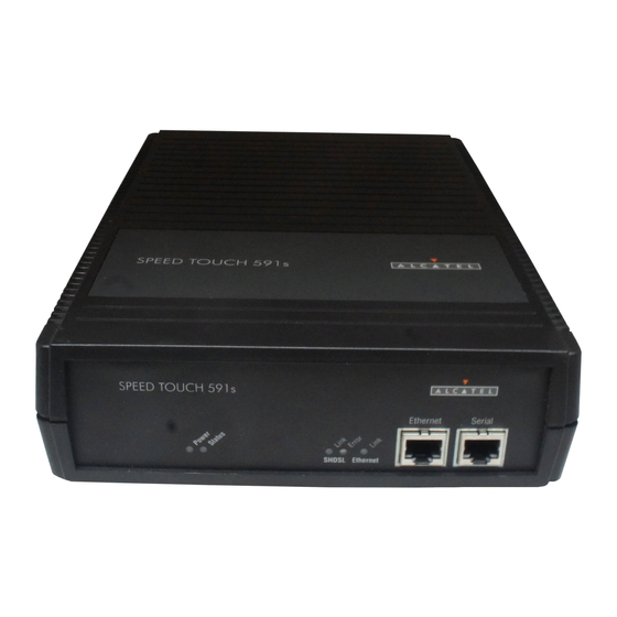
• E1 circuit emulation Figure 1-1 shows the front view of the Speed Touch 591s, which is the same for all versions. Figure 1-2 shows the back view of the frame relay and V.35/X.21 circuit emulation version, and Figures 1-3 and 1-4 show the back views of the T1 and E1 circuit emulation versions, respectively. - Page 25 1 — Introduction Figure 1-2 Back view of the frame relay and V.35/X.21 CE Speed Touch 591s Network Port DSR DTR User Port Power DCD/I RTS/C MTCE 14636 Figure 1-3 Back view of the T1 CE Speed Touch 591s Network Port...
-
Page 26: Compatibility
75 E1 coaxial cabling. The Speed Touch 591s has its own NMTI, which can be accessed either locally on the serial port, or remotely using a 5620 Network Manager. Table 1-1 lists the power requirements for the Speed Touch 591s. -
Page 27: Part Numbers
1 — Introduction Part numbers Table 1-2 lists part numbers for the various versions of the Speed Touch 591s. Table 1-2 Part numbers for the Speed Touch 591s Component Part number Speed Touch 591s V.35 FR, Release 2.0 90-8056-01 Speed Touch 591s V.35 CE, Release 2.0 90-8056-02 Speed Touch 591s T1 CE, Release 2.0... - Page 28 1 — Introduction Speed Touch 591s Technical Practices 90-8785-01 February 2001...
- Page 29 2 — Features and typical applications Frame relay V.35/X.21 circuit emulation T1/E1 circuit emulation Speed Touch 591s Technical Practices February 2001 90-8785-01...
-
Page 30: Features And Typical Applications
2 — Features and typical applications Frame relay The frame relay Speed Touch 591s provides the following key features: • support for SHDSL payload rates of 192, 384, 512, 768, 1024, 1152, 1536, 2048, and 2304 kb/s • frame relay UNI, PVC support •... - Page 31 7350 ASAM 15104 Figure 2-3 Frame forwarding SHDSL ST591s Frame user 7350 ASAM SHDSL network ST591s Frame user 7350 ASAM (PPP, X.25, etc. protocols) SHDSL Frame network ST591s 7350 ASAM 15106 Speed Touch 591s Technical Practices February 2001 90-8785-01...
-
Page 32: V.35/X.21 Circuit Emulation
2 — Features and typical applications V.35/X.21 circuit emulation The V.35/X.21 circuit emulation Speed Touch 591s provides the following key features: • support for SHDSL payload rates of 192, 384, 512, 768, 1024, 1152, 1536, 2048, and 2304 kb/s •... -
Page 33: T1/E1 Circuit Emulation
2 — Features and typical applications T1/E1 circuit emulation The T1/E1 circuit emulation versions of the Speed Touch 591s provide the following key features: • support for SHDSL payload rates of 192, 384, 512, 768, 1024, 1152, 1536, 2048, and 2304 kb/s •... - Page 34 2 — Features and typical applications Speed Touch 591s Technical Practices 90-8785-01 February 2001...
- Page 35 Installation 3 — Installation Speed Touch 591s Technical Practices February 2001 90-8785-01...
-
Page 37: Verifying The Shipment
3 — Installation Verifying the shipment Installing the Speed Touch 591s and power supply Speed Touch 591s Technical Practices February 2001 90-8785-01... -
Page 38: Installation
3 — Installation Verifying the shipment Verify the Speed Touch 591s shipment for completeness and serviceability. Procedure 3-1 Verifying the shipment Make up an inventory form (see sample form in Table 3-1). As you unpack, record the description, part number, serial number, and manufacturing code of each component in the appropriate column. -
Page 39: Installing The Speed Touch 591S And Power Supply
Site requirements The Speed Touch 591s must be installed in a clean, dry, well-ventilated area that meets the requirements listed in Table 3-2. Speed Touch 591s Technical Practices... -
Page 40: Hardware Required
Hardware required The Speed Touch 591s power supply (see Table 1-2) and ferrite bead (supplied by the customer) are required. Speed Touch 591s Technical Practices 90-8785-01... - Page 41 3 — Installation Procedure 3-2 Installing the Speed Touch 591s Plug in the power supply to the power outlet on the Speed Touch 591s. Plug in the power supply to an electrical outlet. Plug the network cable into the network port.
- Page 42 3 — Installation Speed Touch 591s Technical Practices 90-8785-01 February 2001...
- Page 43 8 — Configuring the V.35/X.21 CE user port 9 — Configuring V.35/X.21 CE connections 10 — Configuring the T1/E1 CE port 11 — Configuring T1/E1 CE connections 12 — Configuring T1/E1 CE channel groups Speed Touch 591s Technical Practices February 2001 90-8785-01...
- Page 45 4 — Configuring generic node parameters Node parameter configuration Configuring the network port Speed Touch 591s Technical Practices February 2001 90-8785-01...
-
Page 46: Configuring Generic Node Parameters
CTLIP <ipaddress> SUBNET_MASK <mask> PROG_TO_CURR DESTIP <ipaddress> CTL_VP/VC <vpi/vci> SK002933 Table 4-1 lists the node parameters that can be configured on the Speed Touch 591s. Table 4-1 Node parameters Parameter Options Default value Baud rate 600, 1200, 2400, 4800, 9600, 19200... -
Page 47: Configuring The Node Name
12 alphanumeric characters excluding space, tab, question mark, and percent sign Configuring the NMTI session timeout The session timeout for the NMTI on the Speed Touch 591s can be configured or set to zero (0) to disable it. Speed Touch 591s Technical Practices... -
Page 48: Changing The Password
1 and 24 Changing the password The default password for the Speed Touch 591s is set to <mainstreet>. Passwords must contain between 8 and 12 alphanumeric characters with no spaces, and are not case sensitive. - Page 49 DSLAM—DSLAMs that support CPSS or DSLAMs that do not support CPSS. If the Speed Touch 591s is connected to a 7350 ASAM, configure the DSLAM type as 7350. If the Speed Touch 591s is connected to a 7300 ASAM or any other DSLAM, configure the DSLAM type as 7300.
- Page 50 Configuring the control VP/VC The VP/VC used to carry management signals can be configured manually when the Speed Touch 591s is operating with a 7300 ASAM, because the 7300 ASAM does not support CPSS signals. The new control VP/VC is not applied until the control IP Note —...
- Page 51 Refer to Alcatel 7350 ASAM Technical Practices for further information on access levels. Level 0 access allows read-only access to all node management functions on the Speed Touch 591s and does not require a password. Only a level 5 user can configure level 0 access.
-
Page 52: Configuring The Network Port
4 — Configuring generic node parameters Configuring the network port Since the Speed Touch 591s is a slave to the CO device at the other end of the SHDSL line, the majority of network port parameters are configured by the CO device. - Page 53 5 — Configuring frame relay port parameters Configuring the user port name and options Configuring the user port stream Configuring user port stream options Configuring frame forwarding stream options 5-14 Speed Touch 591s Technical Practices February 2001 90-8785-01...
-
Page 54: Configuring Frame Relay Port Parameters
5 — Configuring frame relay port parameters Configuring the user port name and options The softkey structure for configuring the name and options for the Speed Touch 591s user port is shown below. CONFIG OBJECT PORT <U> NAME <name> OPTIONS... - Page 55 Procedure 5-1 Naming the user port CONFIG — OBJECT — PORT — <U> — NAME — <name> where name contains a maximum of 15 characters excluding space, tab, period, question mark, and percent sign Speed Touch 591s Technical Practices February 2001 90-8785-01...
- Page 56 — OPTIONS — CTRL_LEADS — OUTPUTS Select: DSR or DCD/I or CTS or TM Select: For DSR or TM: FORCE_ON* or FORCE_OFF or IND_MAINT* (TM output only) For DCD/I or CTS: ACTIVE* or FORCE_ON or FORCE_OFF Speed Touch 591s Technical Practices 90-8785-01 February 2001...
- Page 57 — OPTIONS — CLOCKING — CLOCK_RATE — 9.6 kb/s or 19.2 kb/s or 48 kb/s or n*64 kb/s <value> where value is the value of n (1 to 32), used as a multiplying factor for 64 kb/s Speed Touch 591s Technical Practices February 2001 90-8785-01...
-
Page 58: Configuring The User Port Stream
Procedure 5-9 Configuring the stream name CONFIG — OBJECT — PORT — <U> — STREAM — NAME — <name> where name contains a maximum of 15 characters excluding space, tab, period, question mark, and percent sign Speed Touch 591s Technical Practices 90-8785-01 February 2001... - Page 59 (16 to 4472 bytes) Application type The Speed Touch 591s can be configured to ensure quality of service for frame relay traffic over the SHDSL line (in which case, an equivalence is made between certain frame relay and ATM services), or to simply forward frames.
-
Page 60: Configuring User Port Stream Options
PORT <U> STREAM OPTIONS THRESHOLD PACING <value> PVC_MGMNT HDLC NUM_FLAGS <number> INVERTED/ STANDARD* HEARTBEAT <value> STATUS_RATE <value> ALARM_FILTER TYPE TIMEOUT <value> THRESHOLD ANNEX_A ANNEX_D AUTO-NET STREAM NONE* LOW_DELAY COM_THRUPUT BEST_EFFORT REAL_TIME SK002900 Speed Touch 591s Technical Practices 90-8785-01 February 2001... - Page 61 No. of alarms 0 to 255 Interval 0 to 60 min, in increments of 5 min No. of alarms 0 to 255 Interval 0 to 60 min, in increments of 5 min Speed Touch 591s Technical Practices February 2001 90-8785-01...
- Page 62 (see Table 5-3 for values) Pacing The Speed Touch 591s uses pacing to control the rate at which frame relay and frame forwarding traffic travels from the user port to the network port. Pacing smooths out traffic peaks so that the data is transmitted more evenly, thus avoiding peaks at the receiving end, usually a central node.
- Page 63 HDLC The Speed Touch 591s user port can be configured to support either standard or inverted HDLC. The minimum number of flags transmitted between HDLC frames can also be configured. The default setting is 1 flag (back-to-back frames).
- Page 64 THRESHOLD Enter: ERRORS — <errors> where errors is the number of allowable errors (see Table 5-4) Enter: EVENTS — <events> where events is the number of allowable events (see Table 5-4) 5-12 Speed Touch 591s Technical Practices 90-8785-01 February 2001...
- Page 65 (see Table 5-4) Enter: INTERVAL — <interval> where interval is the interval over which the alarms are detected (see Table 5-4) Speed Touch 591s Technical Practices 5-13 February 2001 90-8785-01...
-
Page 66: Configuring Frame Forwarding Stream Options
CONFIG — OBJECT — PORT — <U> — STREAM — OPTIONS — THRESHOLDS — ACT or < > SCT or MCT — value where value is the desired threshold in ms (see Table 5-3) 5-14 Speed Touch 591s Technical Practices 90-8785-01 February 2001... -
Page 67: Configuring Frame Relay Connections
6 — Configuring frame relay connections Configuring frame relay connection options Configuring frame relay traffic parameters Configuring network interworking Configuring service interworking Configuring frame forwarding connection options Speed Touch 591s Technical Practices February 2001 90-8785-01... -
Page 68: Configuring Frame Relay Connection Options
A connection is identified by its two endpoints—one at the user port, the other at the network port. The two endpoints are selected as described below. Refer to Alcatel 7350 ASAM Technical Practices for further information on endpoint identifiers. Speed Touch 591s Technical Practices 90-8785-01 February 2001... -
Page 69: Connection Information
If there are too many connections to fit on the screen, select an option to view the other connections. For connections further down the list, select: PAGE_DOWN For connections near the beginning of the list, select: PAGE_UP To display the original connection information, select: SHOW_CONNECT Speed Touch 591s Technical Practices February 2001 90-8785-01... -
Page 70: Configuring Frame Relay Traffic Parameters
<U;S1/Ddlci> or <U;Ddlci>, and dlci is a value from 16 to 1007, or <N;0/vci>, and vci is a VCI number from 32 to 157 For further information on service categories, refer to Alcatel 7350 ASAM Technical Practices. Speed Touch 591s Technical Practices 90-8785-01 February 2001... -
Page 71: Configuring Network Interworking
Table 6-2 Network interworking parameters Parameter Options Default value PVC management Enable, Disable Enable DE mapping DE=CLP DE=CLP DE=FR_SSCS CLP mapping CLP=DE CLP=DE CLP=0 CLP=1 NIWF DLCI 16 to 991 1022 1022 Speed Touch 591s Technical Practices February 2001 90-8785-01... - Page 72 <U;S1/Ddlci> or <U;Ddlci>, and dlci is a value from 16 to 1007, or <N;0/vci>, and vci is a VCI number from 32 to 157 dlci is a valid network interworking DLCI (see Table 6-2) Speed Touch 591s Technical Practices 90-8785-01 February 2001...
-
Page 73: Configuring Service Interworking
For transparent service interworking: TRANSPARENT* For translated service interworking: TRANSLATED then enter: STANDARD or <profile_no.> where profile_no. is the number of a configured translation profile; refer to Alcatel 7350 ASAM Technical Practices for further information Speed Touch 591s Technical Practices February 2001 90-8785-01... -
Page 74: Configuring Frame Forwarding Connection Options
Refer to section 6.1 for details. Traffic pacing is enabled by default and cannot be disabled. Speed Touch 591s Technical Practices 90-8785-01 February 2001... - Page 75 7 — TCA profiles Overview TCA profile types and parameters Maximum permissible time FRCC-type TCA profiles FRSC-type TCA profiles Speed Touch 591s Technical Practices February 2001 90-8785-01...
-
Page 76: Tca Profiles
15 min or every 24 h. It then determines whether any statistics counter has exceeded its user-defined threshold over a sufficient period of time on the user port on the Speed Touch 591s to justify generating an alarm. -
Page 77: Tca Profile Types And Parameters
Touch 591s itself, and FRSC corresponds to congestion on the user port. When a TCA profile is configured for the Speed Touch 591s, you must first choose the type of congestion for which to define thresholds and profiles. Procedures for defining a Speed Touch 591s TCA profile differ slightly depending on whether FRCC or FRSC is chosen. -
Page 78: Maximum Permissible Time
CONFIG — SYSTEM — TCA_PROFILE — FRSC — <1> — PERF_PARAMTRS — SCT — <15> The next step is to configure the values for the thresholds. The procedure differs slightly, depending on whether the profile is FRCC or FRSC. Speed Touch 591s Technical Practices 90-8785-01 February 2001... -
Page 79: Frcc-Type Tca Profiles
Table 7-2 Threshold values for frame relay system congestion Threshold Range (%) Default value 1 to 100 1 to 100 The value configured for SCT must always be greater than Note — the value configured for MCT. Speed Touch 591s Technical Practices February 2001 90-8785-01... - Page 80 Procedure 7-3 Displaying FRCC-type TCA profiles Enter: CONFIG — SYSTEM — TCA_PROFILE — <FRCC> Figure 7-1 shows the list of FRCC-type TCA profiles for the Speed Touch 591s that is displayed on the NMTI. To list the parameter thresholds for a profile, enter: <profile_number>...
- Page 81 Note — The FRCC-type TCA profile screen (but not the parameter threshold screen) can also be viewed via the maintenance menu by selecting: MAINT — SYSTEM — TCA_PROFILE <FRCC> — Refer to chapter 13 for information on Speed Touch 591s maintenance operations. Speed Touch 591s Technical Practices February 2001 90-8785-01...
-
Page 82: Frsc-Type Tca Profiles
In FRSC profiles, ACT, SCT, and MCT are expressed in milliseconds because they are thresholds applied on the four frame relay queues, based on the amount of time data spends in the queues. Table 7-3 lists these values. Speed Touch 591s Technical Practices 90-8785-01 February 2001... - Page 83 Press <Esc> to move up a level in the softkey tree. Select: TCA_PROFILE — CONGESTION — PROFILE_NUM At this stage the available profiles can be displayed by pressing <Esc> <1>. Enter: <1> — TCA_PROFILE — CONGESTION — ENABLE Speed Touch 591s Technical Practices February 2001 90-8785-01...
- Page 84 9-QUIT To list the parameter thresholds for a profile, enter: <profile_number> where profile_number is the number of the profile The parameter threshold settings for the profile are displayed (see Figure 7-4). 7-10 Speed Touch 591s Technical Practices 90-8785-01 February 2001...
- Page 85 Note — The FRSC-type TCA profile screen (but not the parameter threshold screen) can also be viewed via the maintenance menu by selecting: MAINT — SYSTEM — TCA_PROFILE <FRSC> — Refer to chapter 13 for information on maintenance operations. Speed Touch 591s Technical Practices 7-11 February 2001 90-8785-01...
- Page 86 7 — TCA profiles 7-12 Speed Touch 591s Technical Practices 90-8785-01 February 2001...
- Page 87 8 — Configuring the V.35/X.21 CE user port Configuring the user port name and options Configuring user port circuit parameters Speed Touch 591s Technical Practices February 2001 90-8785-01...
-
Page 88: Configuring The V.35/X.21 Ce User Port
8 — Configuring the V.35/X.21 CE user port Configuring the user port name and options The softkey structure for configuring the name and options for the Speed Touch 591s user port is shown below. CONFIG OBJECT PORT <U> NAME <name>... - Page 89 When the test mode lead is set to Ind_maint, it is controlled by software-initiated maintenance. The lead is forced on when a maintenance action such as a loopback is applied to the Speed Touch 591s, and it is forced off when all maintenance actions are removed.
- Page 90 Procedure 8-5 Restoring default values for the control leads CONFIG — OBJECT — PORT — <U> — OPTIONS — CTRL_LEADS — SET_DEFAULT Table 8-1 lists the default values for the control leads. Speed Touch 591s Technical Practices 90-8785-01 February 2001...
-
Page 91: Configuring User Port Circuit Parameters
Caution — configured connections are removed, and the user port reverts to the disabled state. Refer to sections 9.1 and 13.3 for details on how to configure connections and enable the user port. Speed Touch 591s Technical Practices February 2001 90-8785-01... - Page 92 8 — Configuring the V.35/X.21 CE user port Table 8-2 lists the circuit parameters that can be configured on the Speed Touch 591s user port. Table 8-2 Circuit parameters Parameter Options Default value AAL service type UDT, SDT_w/BASIC Playout buffer size 1 to 12 ms, in increments of 0.5 ms...
- Page 93 Partial cell filling minimizes cell assembly delay by only partially filling the cells with user data and filling the remaining space with padding octets. This speeds up cell assembly because the Speed Touch 591s does not have to wait for an entire cell of data to be received before sending the cell.
- Page 94 8 — Configuring the V.35/X.21 CE user port Speed Touch 591s Technical Practices 90-8785-01 February 2001...
-
Page 95: Configuring V.35/X.21 Ce Connections
9 — Configuring V.35/X.21 CE connections Configuring connection options Speed Touch 591s Technical Practices February 2001 90-8785-01... -
Page 96: Configuring Connection Options
Connections in the Speed Touch 591s are created between the user and the network ports and are thus internal to the Speed Touch 591s. A connection in the Speed Touch 591s is identified by its two endpoints—one at the user port, the other at the network port. - Page 97 9 — Configuring V.35/X.21 CE connections Disconnecting an endpoint A connection can be disconnected by disconnecting either endpoint. Procedure 9-3 Disconnecting an endpoint CONFIG — CONNECT — <U> — DISCONNECT Speed Touch 591s Technical Practices February 2001 90-8785-01...
- Page 98 9 — Configuring V.35/X.21 CE connections Speed Touch 591s Technical Practices 90-8785-01 February 2001...
- Page 99 Configuring the T1/E1 port name and service options 10-2 10.2 Configuring the T1 port physical options 10-5 10.3 Configuring the E1 port physical options 10-10 10.4 Configuring trunk conditioning parameters 10-11 Speed Touch 591s Technical Practices 10-1 February 2001 90-8785-01...
-
Page 100: Configuring The T1/E1 Ce Port
Procedure 10-1 Naming the T1/E1 port CONFIG — OBJECT — PORT — <U> — NAME — <name> where name contains a maximum of 15 characters excluding space, tab, period, question mark, and percent sign 10-2 Speed Touch 591s Technical Practices 90-8785-01 February 2001... - Page 101 Provides SDT service and transmits signaling bits SDT_CAS Procedure 10-2 Configuring the AAL service type CONFIG — OBJECT — PORT — <U> — OPTIONS — AAL_SERVICE — UDT* or UDT_PERFMON or SDT_BASIC or SDT_CAS Speed Touch 591s Technical Practices 10-3 February 2001 90-8785-01...
- Page 102 Procedure 10-3 Configuring the playout buffer size CONFIG — OBJECT — PORT — <U> — OPTIONS — PLAYOUT_BUFF — <value> where value is a value between 1 and 12 ms, in increments of 0.5 ms 10-4 Speed Touch 591s Technical Practices 90-8785-01 February 2001...
-
Page 103: Configuring The T1 Port Physical Options
The softkey structure for configuring the physical options for the T1 port is shown below. CONFIG OBJECT PORT <U> OPTIONS PHYSICAL DSX1* FRAMING ALARM_TIME SYNCHRONIZE MORE NETWORK ESF* RBS <channel> ZERO_SUPPRESS DECLARE <value> CLEAR <value> RDI_CLEAR B8ZS* ON_LOF_CLEAR* ON_RESYNCH SK002857 Speed Touch 591s Technical Practices 10-5 February 2001 90-8785-01... - Page 104 Table 10-3. When the port is configured for DSX1 termination, the line length can be configured to be one of the values shown in Table 10-3. 10-6 Speed Touch 591s Technical Practices 90-8785-01 February 2001...
- Page 105 The framing type for the T1 port can be configured to be ESF or D4. The default is ESF. Procedure 10-5 Configuring the framing type CONFIG — OBJECT — PORT — <U> — OPTIONS — PHYSICAL — FRAMING — ESF* or D4 Speed Touch 591s Technical Practices 10-7 February 2001 90-8785-01...
- Page 106 If the port is configured for UDT or monitored UDT AAL service mode, JB7 is not available. The default is B8ZS encoding. Procedure 10-7 Configuring zero suppression CONFIG — OBJECT — PORT — <U> — OPTIONS — PHYSICAL — MORE — ZERO_SUPPRESS — B8ZS* or JB7 10-8 Speed Touch 591s Technical Practices 90-8785-01 February 2001...
- Page 107 Chan # column and n2 is the last channel in the range in the Chan # column Select: ON or OFF Speed Touch 591s Technical Practices 10-9 February 2001 90-8785-01...
-
Page 108: Configuring The E1 Port Physical Options
Not applicable when the AAL service type is configured as UDT The procedures for configuring alarm declaration and clearing times and CRC framing are the same as those used for the T1 port; refer to section 10.2 for details. 10-10 Speed Touch 591s Technical Practices 90-8785-01 February 2001... -
Page 109: Configuring Trunk Conditioning Parameters
• an LCD through the ATM network occurs in the connection The data and signaling values that are transmitted for each channel of the T1 or E1 port can be configured. Speed Touch 591s Technical Practices 10-11 February 2001 90-8785-01... - Page 110 Speed Touch 591s. The data path pattern is set to all 1s for channels on the Speed Touch 591s for faults that preclude the reception of a valid data pattern from the interface, such as LOF.
- Page 111 Table 10-7 lists the configuration options for the data path. Table 10-7 Data path options for trunk conditioning Function Bit pattern Softkey The Speed Touch 591s transmits an 8-character bit Configurable CUSTOM pattern that matches the requirements of a downstream device. The bit pattern is user configurable.
- Page 112 CH column n2 is the last channel in the range in the CH column Select the option. DISABLE or IDLE or SEIZED 10-14 Speed Touch 591s Technical Practices 90-8785-01 February 2001...
- Page 113 To transmit a bit pattern of seized fault signaling, enter: CODE_1 — <abcd> where a, b, c, and d are 0 or 1 then: CODE_2 — <abcd> where a, b, c, and d are 0 or 1 Speed Touch 591s Technical Practices 10-15 February 2001 90-8785-01...
- Page 114 8-character bit pattern To transmit a signal that indicates that the multiplexer is out of service, select: MUX_OOS To transmit a signal that indicates a fault on the upstream device, select: IDLE 10-16 Speed Touch 591s Technical Practices 90-8785-01 February 2001...
-
Page 115: Configuring T1/E1 Ce Connections
11 — Configuring T1/E1 CE connections 11.1 Connection options 11-2 Speed Touch 591s Technical Practices 11-1 February 2001 90-8785-01... -
Page 116: Connection Options
Connections in the Speed Touch 591s are created between the user and network ports, and are thus internal to the Speed Touch 591s. A connection in the Speed Touch 591s is identified by its two endpoints—one at the user port, the other at the network port. - Page 117 U in UDT mode or U;group in SDT mode, and group is a channel group identifier—CG1 to CG24 for a T1 port and CG1 to CG31 for an E1 port Speed Touch 591s Technical Practices 11-3 February 2001...
- Page 118 11 — Configuring T1/E1 CE connections 11-4 Speed Touch 591s Technical Practices 90-8785-01 February 2001...
- Page 119 Displaying channels in a channel group 12-5 12.6 Configuring the padding octet pattern 12-5 12.7 Configuring the playout buffer size 12-6 12.8 Configuring the number of data octets 12-7 12.9 Deleting channels and channel groups 12-8 Speed Touch 591s Technical Practices 12-1 February 2001 90-8785-01...
-
Page 120: Configuring T1/E1 Ce Channel Groups
A channel group is identified by the lowest-numbered channel in the group. For example, if the channel group consists of channels 4, 5, 6, and 7, the channel group is identified as CG4. 12-2 Speed Touch 591s Technical Practices 90-8785-01 February 2001... -
Page 121: Creating Channel Groups
CAS, timeslots 0 and 16 are reserved for signaling and cannot be added to a channel group. For E1 CE channel groups configured for BASIC, timeslot 0 is reserved for signaling and cannot be added to a channel group. Speed Touch 591s Technical Practices 12-3 February 2001... -
Page 122: Naming Channel Groups
U;group, and group is a channel group identifier—CG1 to CG24 for a T1 port and CG1 to CG31 for an E1 port name is a string containing a maximum of 15 characters excluding space, tab, question mark, and percent sign 12-4 Speed Touch 591s Technical Practices 90-8785-01 February 2001... -
Page 123: Displaying Channels In A Channel Group
E1 or T1 versions can be configured to any hexadecimal number, as specified in ITU I.363.X. Procedure 12-5 Configuring the padding octet pattern CONFIG — SYSTEM — PAD_OCTET_VAL — <value> where value is a value between 00 and FF Speed Touch 591s Technical Practices 12-5 February 2001 90-8785-01... -
Page 124: Configuring The Playout Buffer Size
CDV. The difference between the median fill level and the buffer size is the tolerance of the channel group for positive CDV. The median fill level on the Speed Touch 591s is set to half the buffer size and cannot be configured. -
Page 125: Configuring The Number Of Data Octets
To use only some of the available payload octets, enter: <octet> where octet is a multiple of 4 from 4 to 44 To use all of the available payload octets, select: Speed Touch 591s Technical Practices 12-7 February 2001 90-8785-01... -
Page 126: Deleting Channels And Channel Groups
1 to 24 for a T1 CE port or from 1 to 31 for an E1 CE port To delete a channel group from the system, enter: DEL_CHANNEL 12-8 Speed Touch 591s Technical Practices 90-8785-01 February 2001... - Page 127 Maintenance 13 — Maintenance and file transfers 14 — Troubleshooting 15 — Statistics Speed Touch 591s Technical Practices February 2001 90-8785-01...
-
Page 129: Maintenance And File Transfers
13 — Maintenance and file transfers 13.1 System maintenance 13-2 13.2 Network port maintenance 13-4 13.3 User and T1/E1 port maintenance 13-5 13.4 File transfers 13-9 Speed Touch 591s Technical Practices 13-1 February 2001 90-8785-01... -
Page 130: System Maintenance
13 — Maintenance and file transfers 13.1 System maintenance The following maintenance options are available for the Speed Touch 591s: • specifying the active memory bank, erasing memory banks, and performing other software maintenance tasks • forcing the Speed Touch 591s to boot up •... - Page 131 Note — "YES" in the NMTI-Affected column indicates that the TCA profile has been configured via the Speed Touch 591s NMTI. "NO" indicates that the profile is unconfigured (its default values have not been altered), or that it has been configured via the 5620 Network Manager.
-
Page 132: Network Port Maintenance
SNR margin, PSD mask used, and power backoff settings. Figure 13-3 shows an example of an NMTI screen for network port maintenance information. Figure 13-3 Speed Touch 591s network port maintenance screen Speed Touch 591s Generic... -
Page 133: User And T1/E1 Port Maintenance
5 min, although the loopback can be cleared manually before the 5 min expires. Note — If a Telnet session is used to access the Speed Touch 591s NMTI, the loopback cannot be cleared before the 5 min expires. Procedure 13-2 Configuring a loopback MAINT —... - Page 134 The loopback available on the user port is a bidirectional loopback—data on the user port is looped back within the Speed Touch 591s at the point closest to the data interface, while network data is looped back to the network. This loopback tests the data interface at the user port.
- Page 135 The equipment loopback tests the Speed Touch 591s itself. Data received on the SHDSL line at the network port is carried through the Speed Touch 591s, then looped back to the network port when it reaches the T1/E1 port. An AIS is transmitted on the T1/E1 port while the loopback is in place.
- Page 136 — STREAM An example of the information displayed on the NMTI is shown in Figure 13-5. Refer to Alcatel 7350 ASAM Technical Practices for further information on frame relay stream status fields. 13-8 Speed Touch 591s Technical Practices 90-8785-01 February 2001...
-
Page 137: File Transfers
13 — Maintenance and file transfers Figure 13-5 Speed Touch 591s user port stream maintenance screen Speed Touch 591s Generic Node name Maj:Alrm:5 Date Time Stream# Status Name Stream Enabled Stream Congestion Status : REEN Max. FR Frame Size 1600 Bytes... - Page 138 13 — Maintenance and file transfers 13-10 Speed Touch 591s Technical Practices 90-8785-01 February 2001...
-
Page 139: Troubleshooting
14 — Troubleshooting 14.1 LED activity 14-2 14.2 Alarms 14-4 Speed Touch 591s Technical Practices 14-1 February 2001 90-8785-01... -
Page 140: Led Activity
14.1 LED activity All versions of the Speed Touch 591s have five LEDs on their front panel. The frame relay and V.35/X.21 CE versions have eight LEDs on their back panel, and the T1 and E1 circuit emulation versions have ten LEDs on their back panel. Figures 14-1 to 14-4 show the front and back panels of the various versions of the Speed Touch 591s. - Page 141 (always off for X.21) RTS/C Solid green Request to Send (V.35/V.36/TIA/EIA-449) or Control (X.21) MTCE Solid red Maintenance. The Speed Touch 591s is in test mode. Note E1/T1 circuit emulation versions only Speed Touch 591s Technical Practices 14-3 February 2001 90-8785-01...
-
Page 142: Alarms
The SHDSL Link LED turns solid green. 14.2 Alarms The Speed Touch 591s stores certain alarms. Table 14-2 lists the maximum number of alarm records that the Speed Touch 591s can store in each queue. Table 14-2 Alarm queue size... - Page 143 14 — Troubleshooting Table 14-3 Speed Touch 591s alarms Alarm Queue Description V.35/X.21 T1/E1 Too Many RDI Detected Critical OAM alarm Too many AIS Detected Critical OAM alarm System Restart Major Housekeeper processor restarted Stream In Service Major Frame relay stream alarm...
- Page 144 14 — Troubleshooting 14-6 Speed Touch 591s Technical Practices 90-8785-01 February 2001...
-
Page 145: Statistics
15 — Statistics 15.1 Frame relay statistics 15-2 15.2 V.35/X.21 CE statistics 15-6 15.3 T1 CE statistics 15-9 15.4 E1 CE statistics 15-12 Speed Touch 591s Technical Practices 15-1 February 2001 90-8785-01... -
Page 146: Frame Relay Statistics
PVC_MGMT SK002467 Displaying user port statistics The only statistics available for the Speed Touch 591s user port are frame relay stream statistics. For details on frame relay stream statistics, refer to Alcatel 7350 ASAM Technical Practices. Displaying network port statistics ATM and AAL5 statistics can be displayed for the Speed Touch 591s network port. - Page 147 Number of AAL5 PDUs discarded by the port for other reasons Procedure 15-1 Displaying AAL5 statistics STATS — OBJECT — PORT — <N> — AAL5 Figure 15-1 shows the NMTI screen for AAL5 statistics. Speed Touch 591s Technical Practices 15-3 February 2001 90-8785-01...
- Page 148 ATM statistics are displayed. For details on frame relay and ATM endpoint statistics, refer to Alcatel 7350 ASAM Technical Practices. Displaying system statistics The system statistics available for the Speed Touch 591s are standard frame relay statistics. 15-4 Speed Touch 591s Technical Practices...
- Page 149 15 — Statistics Figure 15-2 shows the NMTI screen for Speed Touch 591s system statistics. Figure 15-2 System statistics 1-hour summary screen Speed Touch 591s Generic Node name Alrm:5 Date Time Display Interval : Current Snapshot taken at: 08FEB1999 17:40...
-
Page 150: V.35/X.21 Ce Statistics
Displaying user port statistics AAL1 statistics can be displayed for the user port on the V.35/X.21 circuit emulation version of the Speed Touch 591s. Figure 15-3 shows a sample NMTI screen for AAL1 statistics in UDT mode. Figure 15-3 User port statistics sample screen... - Page 151 AAL1 Pointer Reframes Number of times that the AAL1 reassembler found that an SDT pointer was not where it was supposed to be and had to reacquire a pointer (SDT mode only). Speed Touch 591s Technical Practices 15-7 February 2001 90-8785-01...
- Page 152 Alcatel 7350 ASAM Technical Practices. Displaying endpoint statistics ATM statistics can be displayed for the network endpoint—for details on ATM endpoint statistics, refer to Alcatel 7350 ASAM Technical Practices. 15-8 Speed Touch 591s Technical Practices 90-8785-01 February 2001...
-
Page 153: T1 Ce Statistics
15 — Statistics 15.3 T1 CE statistics The softkey structure for statistics on the T1 CE version of the Speed Touch 591s is shown below. STATS OBJECT PORT <U> PORT <N> ENDPOINT <endpoint> CHANNELGROUP <endpoint> AAL1 15_MINUTE 24_HOUR 15_MINUTE 1_HOUR... - Page 154 Frame Counts Controlled Not used for the T1 port; always reads n/a. Slip Seconds Valid Number of statistics collection intervals that were successfully 15-min Intervals completed over the past 24-h period 15-10 Speed Touch 591s Technical Practices 90-8785-01 February 2001...
- Page 155 Displaying channel group statistics AAL1 statistics can be displayed for channel groups configured on the T1 port. They are the same as those for the V.35/X.21 CE version of the Speed Touch 591s; refer to section 15.2 for details. Speed Touch 591s Technical Practices...
-
Page 156: E1 Ce Statistics
To clear statistics, select: TEMP_CLEAR Refer to Figure 15-3 for an example of AAL1 statistics. 15.4 E1 CE statistics The softkey structure for statistics on the E1 CE version of the Speed Touch 591s is shown below. STATS OBJECT ENDPOINT <endpoint>... - Page 157 Number of occurrences of either a BPV or EXZ error event error Far End Block Errors Number of far-end block errors received Frame Alignment Number of incorrect framing alignment patterns received Signal Errs CRC4 Errors Number of incorrect CRC4 blocks received Speed Touch 591s Technical Practices 15-13 February 2001 90-8785-01...
- Page 158 When the current 15-min interval displays, specify how the statistics are to be displayed. To clear the statistics and display them as they increase, select: TEMP_CLEAR To display the accumulated statistics that have been cleared by TEMP_CLEAR, select: CURRENT 15-14 Speed Touch 591s Technical Practices 90-8785-01 February 2001...
- Page 159 AAL1 statistics can be displayed for channel groups configured on the E1 port. They are the same as those for the V.35/X.21 CE version of the Speed Touch 591s; refer to section 15.2 for details. The procedure for displaying AAL1 statistics for E1 ports is the same as for T1 ports;...
- Page 160 15 — Statistics 15-16 Speed Touch 591s Technical Practices 90-8785-01 February 2001...
- Page 161 App A. Pin and signal assignments Speed Touch 591s Technical Practices February 2001 90-8785-01...
- Page 162 This appendix contains details of the pin and signal assignments on the Speed Touch 591s user and T1/E1 ports. The user port on the Speed Touch 591s has a unidirectional driver, presenting a fixed DCE gender. Table App A-1 summarizes all interface, gender, clocking, cable, and connector configurations supported.
- Page 163 RTSa SCRb SCRa CTSb CTSa DSRb DSRa DTRb DTRa DCDb DCDa SCTEb SCTEa User port and cable connector at equipment end 12444 The LL and RL pins are not supported. Note — Speed Touch 591s Technical Practices February 2001 90-8785-01...
- Page 164 SCTEa (to pin U) TM (to pin NN) SG (n/c) SG (n/c) User port Cable (part number 90-3577-01) connector at equipment end 12445 Note — The LL and RL pins are not supported. Speed Touch 591s Technical Practices 90-8785-01 February 2001...
- Page 165 The LL and RL pins are not supported. Table App A-2 identifies the RJ45 connector pin assignments for the T1/E1 port on the T1/E1 CE version of the Speed Touch 591s. Table App A-2 RJ45 connector pin assignments for the T1/E1 port...
- Page 166 App A. Pin and signal assignments Speed Touch 591s Technical Practices 90-8785-01 February 2001...
- Page 167 Glossary Speed Touch 591s Technical Practices February 2001 90-8785-01...
- Page 169 It is also known as an RAI or yellow alarm. access rate The effective maximum bandwidth of a frame relay port ASAM ATM subscriber access multiplexer Speed Touch 591s Technical Practices GL-1 February 2001 90-8785-01...
- Page 170 Similar to X.25, CPSS is a packet-switched system used to transfer configuration and status information between nodes. cyclic redundancy check A CRC is a process used to check the integrity of a block of data. GL-2 Speed Touch 591s Technical Practices 90-8785-01 February 2001...
- Page 171 DTR is a V-series control signal sent from the DTE to the DCE indicating that the DTE is powered and ready to communicate. DTR can also be used for hardware flow control. EFCI explicit forward congestion indication Speed Touch 591s Technical Practices GL-3 February 2001 90-8785-01...
- Page 172 An LED is a semiconductor diode that emits light when a current passes through it. local management interface LMI is a frame relay link management protocol defined by Digital Equipment Corporation, Northern Telecom, Cisco, and Stratacom. GL-4 Speed Touch 591s Technical Practices 90-8785-01 February 2001...
- Page 173 MTCE maintenance MTCE is an LED on the Speed Touch 591s, indicating that it is in a maintenance state when lit (usually when a loopback is in progress). NIWF network interworking function An NIWF is an interworking function used to transport frame relay packets across an intermediate network to another frame relay network.
- Page 174 When a user-defined threshold for any one of the statistics in the profile has been exceeded, an alarm is generated. Several statistics counters can therefore be monitored using a single profile. Telco telephone company TIA/EIA Telecommunications Industry Association/Electronics Industries Alliance test mode transmit GL-6 Speed Touch 591s Technical Practices 90-8785-01 February 2001...
- Page 175 Multihop VPCs use multiple VPIs to go from source to destination. Each switch that the VPC traverses cross- connects the VPC from one port and VPI to another port and VPI. Speed Touch 591s Technical Practices GL-7 February 2001...
- Page 176 Glossary GL-8 Speed Touch 591s Technical Practices 90-8785-01 February 2001...
- Page 177 Index Speed Touch 591s Technical Practices February 2001 90-8785-01...
- Page 179 12-5 options, 10-10 naming, 12-4 parameters, 10-10 number of data octets, 12-7 statistics, 15-13 playout buffer, 12-6 EFCI mapping, 6-8 unavailable configurations, 12-7 endpoint statistics, 15-4, 15-8, 15-11, 15-15 endpoints, 11-2 Speed Touch 591s IN-1 February 2001 90-8785-01...
- Page 180 4-3 system, 13-2 service category, 6-4 user port, 13-5 service interworking, 6-7 service types, 8-6 SHDSL technology, 1-2 shipment verification, 3-2 network interworking, 6-5 signal assignments, A-2 network interworking mode, 6-7 signaling, 10-11 IN-2 Speed Touch 591s 90-8785-01 February 2001...
- Page 181 10-8 PVC management parameters, 5-9 T1/E1 connections resetting, 13-6 disconnecting, 11-3 statistics, 15-2 displaying information, 11-3 stream (frame relay), 5-6 endpoints, 11-2 stream options, 5-8 stream parameters, 5-6 V.35/X.21 CE, 8-2 Speed Touch 591s IN-3 February 2001 90-8785-01...
- Page 182 9-2 selecting endpoints, 9-2 V.35/X.21 CE V.35/X.21 user port alarms, 14-5 circuit parameters, 8-5 connection options, 9-2 parameters, 8-3 statistics, 15-6 user port options, 8-2 user port parameters, 8-3 zero suppression, 10-8 IN-4 Speed Touch 591s 90-8785-01 February 2001...
- Page 184 © 2001 Alcatel. All rights reserved. 95-5293-01-00-A...
Need help?
Do you have a question about the Speed Touch 591s and is the answer not in the manual?
Questions and answers