Table of Contents
Advertisement
Quick Links
N O T F O R R E S I D E N T I A L U S E
This Installation Manual provides the information required to install, troubleshoot and
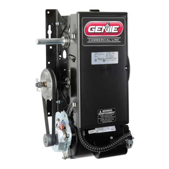
maintain the GCL-J&H
GCL-J
Standard Duty Operator
JACKSHAFT/HOIST
PROPER APPLICATION
Door Type
ALL TYPES
C
o
m
m
™
™
H
&
EZ Limit
™
Multivolt
TensiBelt
Operator Type
HP/Max Door Weight HP/Max Door Weight
(Sectional)
Jackshaft/Hoist
1/2HP = 1120 lbs
Hood Mount or
3/4HP = 1370 lbs
Wall Mount
1HP = 1620 lbs
e
c r
a i
/ l
n I
d
s u
r t
l a i
D
™
™
(Rolling Steel)
1/2HP = 998 lbs
3/4HP = 1220 lbs
1HP = 1440 lbs
o
r o
O
p
e
a r
o t
. r
Advertisement
Table of Contents

Related Manuals for Genie GCL-J&H


Summary of Contents for Genie GCL-J&H
- Page 1 ™ GCL-J & Standard Duty Operator JACKSHAFT/HOIST EZ Limit ™ Multivolt ™ TensiBelt ™ PROPER APPLICATION Door Type Operator Type HP/Max Door Weight HP/Max Door Weight (Sectional) (Rolling Steel) ALL TYPES Jackshaft/Hoist 1/2HP = 1120 lbs 1/2HP = 998 lbs Hood Mount or 3/4HP = 1370 lbs 3/4HP = 1220 lbs...
-
Page 2: Table Of Contents
Table of Contents Section 1 How to use this manual ....... 1.1 Section 7 Special Operational Features. - Page 3 Section 1: How to use this manual The 11 sections of this Installation Manual provide the information required to install, troubleshoot and maintain a this commercial/industrial door operator. Section 2 Section 3 WARNING Failure to correctly perform all steps in sections 4-6 can result in serious injury or death. Sections 4-6 Sections 7-8 Sections 9-11...
-
Page 4: Section 2: Safety Information & Instructions
For the number Periodically lubricate all moving parts of door. of your local Genie® Dealer, call 800-OK-GENIE, and for Genie® Factory Technical Advice, call 800-843-4084. 3. If door has a sensing edge, check In this Manual, the words Danger, Warning, and Caution are used to stress important safety information. -
Page 5: Critical Installation Information
MillerEdge ME, MT and CPT series monitored edge sensors used in combination with Timer-Close Module P/N OPABTCX.S, or OPAKMEIGX.S INTERFACE MODULE. 2) Residential Safe-T-Beam® Monitored Photocells from The Genie® Company, model OSTB-BX (P/N 38176R). 3) Series II Commercial Safe-T-Beam®, Monitored Photocells P/N OPAKPE.S. -
Page 6: Rolling Steel Door Chart
UNTIL ONE OF THESE MONITORED EXTERNAL ENTRAPMENT DEVICES IS INSTALLED, THE OPERATOR WILL NOT ALLOW MOMENTARY CONTACT OPERATION IN THE CLOSE DIRECTION. APPROVED DEVICES ALLOWABLE DOOR WIDTH Miller Edge ME, MT & CPT series monitored edge sensors used in combination with either the Genie® ANY WIDTH Timer-Close Module or Direct connect through STB inputs. -
Page 7: Sectional Door Chart
Section 3: Critical Installation Information Sectional Door Chart (sq. ft.) CommercialSteelInsulated&Non-Insulated Thermospan Thermomark Aluminum Door S eries -> 216 ins. 220 ins. 2415 2415 ins. 2411 2411 ins. 200-20 5150 5200 PU/FIP PU/FIP PU/FIP Max. 16GA. 20GA. 24GA. Nominal Nominal Model UL L is ted 16GA. -
Page 8: Installation
Section 4: Installation Front of Hood The Rolling Steel Door Operator can be assembled for right-hand or left-hand mounting Front of Hood. Fig. 1. (Each model can also be wall mounted. Page 4.2) SOCKET BUTTON HEAD CAP SCREW NOTE: On Jackshaft units, release cable must be installed on operator 112145.0001 before unit is installed. -
Page 9: Chain Couple
Chain Couple The Side Mount Operator can be assembled for right or left hand NOTE: If using slotted mounting holes to mount unit, mounting above or below the door shaft and is available with or you MUST without hoist. use at least 2 lockdown holes in opposite corners to firmly mount unit to wall. - Page 10 Chain Couple (continued) For Hollow Counterbalance Door Shaft: 1) Use non-threaded hole in door shaft sprocket as a guide and drill a 3/8” diameter hole through one side of the door shaft. DRILL HOLE IN THIS SIDE Fig. 3A. OF SHAFT 2) Insert clevis pin through sprocket and shaft to hold sprocket SPROCKET HUB in position.
- Page 11 Chain Couple (continued) (Tension Plate Kit) Kit available separately, P/N 111005.0001.S for 1" door shaft. 111005.0002.S for 1 " door shaft. Installation of optional chain spreader bracket: Fig 4A & 4B 1) Place drive chain sprocket and bearing plate assembly on door shaft as shown.
- Page 12 Hand Chain and Keeper 1) Route the hand chain through the chain guide, around the NOTE: To insure smooth operation, make sure there is no twist in the pocket wheel and back through the chain guide. Fig.5. hand chain before connecting the link ends together. 2) Connect the hand chain ends together as shown in Fig 6.
-
Page 13: Clutch Adjustment
Clutch Adjustment Fig. 9 The Operators have a friction style clutch that can be adjusted. NOTE: The clutch is intended to provide protection for the door, the CLUTCH PULLEY operator and associated equipment. It is not intended for entrapment protection. To Adjust the Clutch WASHER 1) Decrease the compression on the clutch until the operator will... -
Page 14: Wiring
Section 5: Wiring Line Voltage Wiring Fig. 1 LINE INPUT LINE TERMINALS GROUND WARNING Figure 1 • DO NOT apply power to operator until instructed to do so. Three Phase • Corporation recommends that line voltage wiring be performed by a qualified electrician. •... -
Page 15: Low Voltage Control Wiring
Low Voltage Control Wiring (general) Fig. 2 ROUTE LOW VOLTAGE WIRING IN THE SHADED AREA AS SHOWN Optional Accessory 1) Connect all LOW VOLTAGE control circuit wires to this end of VOLTAGE Modules electric box using 1/2” conduit or flexible convoluted tubing. INPUT PLUGS •... -
Page 16: External Wire Diagram
External Wire Diagram See Appendix B for detailed description of terminals. OPEN CLOSE STOP 1-BTN REVERSE REVERSE INTLK INTLK 20-40 VDC @ 250 mA MAX.CURRENT EXT. RADIO CONNECTOR REMOVE Located inside JUMPER WHEN Electric Box INSTALLING REMOVE EXTERNAL JUMPER INTERLOCK IF STOP BUTTON 1-BTN... -
Page 17: Wall Control
Wall Control Figure 3 CONTROL SIGNAL TERMINAL STRIP 3-BUTTON OPEN CLOSE STOP STATION WARNING: OPEN • Wall Control(s) must be located so that the door is within sight of the user and is far enough from the door, or positioned such that CLOSE the user is prevented from coming in contact with the door while Figure 3A... -
Page 18: Interlock Switches (Rolling Steel)
Interlock Switches (Rolling Steel) NOTE: If External Interlock is used, THE JUMPER WIRE BETWEEN THE EXT INTLK TERMINALS MUST BE REMOVED. 1) Optional external interlock switches CONTROL SIGNAL TERMINAL STRIP are required with some Sectional or OPEN CLOSE STOP 1BTN Rolling Steel Doors to prevent the REVERSE REVERSE INTLK... -
Page 19: Interlock Switches (Sectional)
Interlock Switches (Sectional) 1) Optional external interlock switches are CONTROL SIGNAL TERMINAL STRIP NOTE: If External Interlock is used, THE JUMPER WIRE BETWEEN THE required with some Sectional or Rolling Steel EXT INTLK TERMINALS MUST BE REMOVED. NTLK NTLK Doors to prevent the door from operating under certain conditions including the following: •... -
Page 20: Photocell Wiring
Photocell Wiring Monitored Photocells CONNECT WIRES TO EITHER TERMINAL 1) Series II Commercial Monitored photocells and Residential (NOT POLARITY SENSITIVE) Safe-T-Beam® Monitored Photocells. Fig. 7 & 8. Wiring to these CONTROL SIGNAL photocells can be connected to either terminal (they are not polarity sensitive. Figure 7 TERMINAL STRIP ( Troubleshooting on page 8.5) . -
Page 21: Sensing Edge Switch
Sensing Edge Switch Installation Figure 10A CONTROL SIGNAL TERMINAL STRIP NOTE Non-monitored Figure 11 shows an example of a typical sensing edge installation. Left hand side is shown but sensing edge can be REVERSE REVERSE right hand is a mirror image of this. connected directly to 1A) If wiring from sensing edge switch to operator is coiled cord or 2 wire jacketed cord: these terminals. -
Page 22: External Radio
External Radio Installation Although the Operators are equipped with an internal radio, they also provide a universal connection for an external radio. EXTERNAL To Add the External Radio RADIO 1) Plug the 3-wire pigtail (provided) onto the plug connector marked CONNECTOR Optional “EXT RAD.”... -
Page 23: Safety Instructions
WARNING IMPORTANT SAFETY INSTRUCTIONS Verify Line Voltage before making any connections to assure that motor harness is connected to proper motor connector on WARNING - circuit board. To reduce the risk of severe injury or death: 1) Plug motor harness into proper motor connector on circuit board in electric box. -
Page 24: Control Panel
Section 6: Operator Setup Procedure Control Panel Operators include a full function control panel including a liquid crystal Operation Keys, operate display (LCD), calibration keys and Open, Close and Stop keys for on board unit like a 3-button operator control. See Fig. 1. The open, close and stop keys function as a 3-button wall station. -
Page 25: Setting Close Direction
Setting Close Direction The direction of motor rotation depends on mounting position and/or how the OPEN main input power phases are wired. This setting is used to insure the door is SET CLOSE DIR closing and opening according to the input commands. CLOSE Figure 2 STOP... -
Page 26: Setting Braking Rate
Setting Braking Rate 1) If operator is in RUN mode, press CAL/RUN key to enter calibration mode. 2) Press Scroll key until display reads “BRAKING RATE >#.” where # is the CROLL deceleration rate, ranging from 0 to 9. 0=max. braking. 9=Min. OPEN Figure 6. -
Page 27: Setting Travel Limits
Setting Travel Limits NOTE: The recommended setpoint for the DOWN Travel Limit is normally at approximately 2 inches off the floor. This final distance will be covered by the Limit UP and/or DOWN Overrun Function to establish a more accurate seal. 1) If operator is in RUN mode, press CAL/RUN key to enter calibration mode. -
Page 28: Setting Limit Overrun
Setting Limit Overrun This Setting is a matter of trial and Error NOTE: The actual distance that the Overrun function covers is variable depending 1) If operator is in RUN mode, press CAL/RUN key to enter on model of operator and size of the door (nominally about 2 inches of travel). calibration mode. -
Page 29: Monitored Reversing Devices
2) MillerEdge ME and MT series monitored edge sensors used in combination with MillerEdge Interface Module SM-101. (Direct Figure 10 connect through STB inputs). 3) Residential Safe-T-Beam® Monitored Photocells from The Genie® Company, model OSTB-BX (P/N 38176R.S). 4) Series II Safe-T-Beam® Monitored Photocells (P/N OPAKPE.S). 5) Monitored Photocells P/N OPAKPEN4GX.S. -
Page 30: Setting Open & Close Modes
Setting Open and Close Modes (Constant vs Momentary Contact) NOTE: Momentary contact (MOM) or Constant Reverse (C-REV) may not be used unless both the OPEN and CLOSE Limits have been set. OPEN In situations where an external reversing device is either not installed or not 1) If operator is in RUN mode, press CAL/RUN key to enter calibration mode. -
Page 31: (Optional) Transmitter Programming
(Optional) Transmitter Programming Adding a Transmitter LEARN NEW XMTR? CLOSE 1) If operator is in RUN mode, press CAL/RUN key to enter calibration mode. STOP 2) Press SCROLL key (up or down) until display reads “LEARN NEW XMTR? ” SCROL Figure 13. -
Page 32: Setting Mid-Stop Limit
Setting Mid-Stop Limit The Operator includes a programmable Mid-Stop. This feature allows the operator to stop at a user selectable point when opening. It is used when operating very tall doors that only open to their full height occasionally. The Mid-Stop does not effect the operator when closing. -
Page 33: Operator Cycle Count
Section 7: Special Operator Features (No user input) Operator Cycle Count 1) Press CAL/RUN key to enter calibration mode. OPEN 2) Press SCROLL key until display reads “CYCLES>1,2,3 etc. SCROLL CYCLES 1 CLOSE SC OL where the number is the number of open/close cycles the operator has performed. -
Page 34: Operator Type
Operator Type Fig. 3 NOTE: The GDO type is factory set. The installer should not have to set this feature. However, if the GDO type is inadvertently changed, or if a board needs to be replaced in the field, follow these instructions to set GDO type. 1) Press CAL/RUN key to enter calibration mode. -
Page 35: Troubleshooting
Section 8: Troubleshooting Display Operation in Run Mode Operators display their status on the integrated display. Each time the operator runs, stops, reverses or refuses to run, the display will indicate why the action did, or did OPEN not, take place. ERROR CODE 1 41 CLOSE Once an error code has been generated, the operator will continue to display the... -
Page 36: Run Codes
Error Codes (continued) To view the error code memory: OPEN 1) Press CAL/RUN key to enter calibration mode. > ”. 2) Press SCROLL key until display reads “ERROR CODE 1 RUN CODE 1 3C SCROLL CLOSE • The display will begin flashing the error code number and 2-digit STOP error code followed by its description. - Page 37 Run Codes (continued) To view the run code memory: 1) Press CAL/RUN key to enter calibration mode. key until display reads “RUN CODE 1 > .” 2) Press SCROLL SCROLL • The display will begin flashing the run code number and code followed by its description.
-
Page 38: Led Indicators
LED Indicators Fig. 6 Operators include a self-diagnostic circuit board using troubleshooting LED indicators to signal the technician of a problem. Figure 6 PHOTOCELL ENAB TROUBLESHOOTING LED’s PHOTOCELL NORMALLY ON - PHOTOCELL ENABLED OFF - PHOTOCELL DISABLED ENABLE OFF - CHECK AC POWER SUPPLY + 24 VOLTS NORMALLY ON - POWER AVAILABLE CHECK FUSES... - Page 39 Monitored Photocell Self-diagnostic Troubleshooting Chart SOURCE ( RED LED ) SENSOR ( GREEN LED ) INDICATED CONDITION REQUIRED ACTION NONE REQUIRED NORMAL OPERATION 1. CHECK BREAKERS, FUSES, PLUGS 1. POWER HEAD NOT POWERED 2. CHECK WIRING FOR OBVIOUS SHORTS 2. WIRING FROM POWER HEAD BAD 1.
-
Page 40: Service & Maintenance
Section 9: Service and Maintenance Maintenance Schedule The following table provides a schedule of recommended Service and Maintenance items to be completed by a trained service representative. CAUTION: Failure to perform the recommended Service & Maintenance may result in premature failure of the operator. SERVICE ITEM SERVICE INTERVAL (FREQUENCY) EVERY 6 MO. - Page 41 Section 10: Appendix A PARTS LIST Basic Operator Parts ITEM PART NUMBER DESCRIPTION 1/2HP,1 PH, ODP MOTOR 110635.0001 Hoist 110635.0002 3/4HP, 1 P[H, ODP MOTOR 110635.0003 1 HP, 1 PH, ODP MOTOR 11 12 13 110635.0004 1/2HP, 3 PH, ODP MOTOR 3/4HP, 3 P[H, ODP MOTOR 110635.0005 1 HP, 3 PH, ODP MOTOR...
- Page 42 Section 10: Appendix A PARTS LIST Jackshaft ITEM PART NUMBER DESCRIPTION 12 13 110635.0001 1/2HP,1 PH, ODP MOTOR 110635.0002 3/4HP, 1 P[H, ODP MOTOR 110635.0003 1 HP, 1 PH, ODP MOTOR 1/2HP, 3 PH, ODP MOTOR 110635.0004 3/4HP, 3 P[H, ODP MOTOR 110635.0005 110635.0006 1 HP, 3 PH, ODP MOTOR...
- Page 43 PARTS LIST Section 10: Appendix A PART NUMBER DESCRIPTION 110635.0001 1/2HP,1 PH, ODP MOTOR 110635.0002 3/4HP, 1 P[H, ODP MOTOR Jackshaft/Hoist Combo 110635.0003 1 HP, 1 PH, ODP MOTOR 110635.0004 1/2HP, 3 PH, ODP MOTOR 110635.0005 3/4HP, 3 P[H, ODP MOTOR 11 12 13 110635.0006 1 HP, 3 PH, ODP MOTOR...
- Page 44 Section 10: Appendix A Alternate Motor Options* TENV, SINGLE PHASE TEFC, SINGLE PHASE 111309.0001, 1/2 HP, 115/208/230 V 111306.0001, 1/2 HP, 115/208,230 V 111309.0002, 3/4 HP, 115/208/230 V 111306.0002, 3/4 HP, 115/208/230 V 111309.0003, 1 HP, 115/208/230 V 111306.0003, 1 HP, 115/208/230 V TENV, THREE PHASE TEFC, THREE PHASE 111309.0004, 1/2 HP, 208/230/460 V...
- Page 45 Appendix A (continued) Basic Output (A) and Clutch (B) Shafts Parts Hoist PARTS LIST PARTS LIST ITEM ITEM PART NUMBER DESCRIPTION PART NUMBER DESCRIPTION 111074.0001 LIMIT SPROCKET 110669.0001 CLUTCH SHAFT OUTPUT SHAFT BEARINGS 110694.0001 110872.0001 HANDWHEEL SHAFT LOCKING COLLAR 604297.4100 CLUTCHPULLEY 111408.0001 SPACER, OUTPUT SHAFT...
- Page 46 Appendix A (continued) Basic Output (A) and Clutch (B) Shaft Parts Jackshaft PARTS LIST PART NUMBER DESCRIPTION 111074.0001 LIMIT SPROCKET OUTPUT SHAFT BEARINGS 110694.0001 SHAFT LOCKING COLLAR PARTS LIST 604297.4100 SPACER, OUTPUT SHAFT 110819.0002 ITEM PART NUMBER DESCRIPTION SPACER WASHER, 1.015 ID 110393.0001 110669.0001 CLUTCH SHAFT...
- Page 47 Appendix A (cont’) Basic Combination Shaft Parts PARTS LIST 107 110 Hoist/Release Combo ITEM PART NUMBER DESCRIPTION PARTS LIST CLUTCH SHAFT 110669.0001 HANDWHEEL ITEM 110872.0001 PART NUMBER DESCRIPTION 111408.0001 CLUTCHPULLEY 111074.0001 LIMIT SPROCKET CLUTCH SPRING 075197.0000 OUTPUT SHAFT BEARINGS 110694.0001 SLOTTED CLUTCH NUT 110472.0001 604297.4100...
- Page 48 Appendix A (cont’) Basic Electric Box Parts PARTS LIST ITEM PART NUMBER DESCRIPTION 111607.0001 ELECTRICAL BOX ASSY, 1PH, CONT 111607.0002 ELECTRICAL BOX ASSY, 1PH, RELAY ELECTRICAL BOX ASSY, 3PH, CONT 111607.0003 ELECTRICAL BOX ASSY, 3PH, RELAY 111607.0004 ELECTRICAL BOX ASSY, 575V, CONT 111607.0005 111097.0001 ELECTRIC BOX LATCH...
- Page 49 Appendix A (cont’) Electric Box Layout Single Phase Three Phase External Radio Connector Expansion Board Fuse Port Radio Limit Antenna Sensor Input (Coax) Connector Internal Radio Hoist Board 208/ 208/ Interlock 115V 460V 230V 230V Fuse 1 PH Connector 3 PH 1 PH 3 PH Motor...
-
Page 50: Appendix B
Section 10: Appendix B Screw Terminal Assignments INPUT FUNCTION CONNECTION TYPE Normally-Open Dry Contact to GND. Causes door to open if not at Up Limit. Causes a closing door to reverse. OPEN 11-POSITION TERMINAL BLOCK CLOSE Causes door to close if not at Down Limit. Normally-Open Dry Contact to GND. -
Page 51: Run Codes
Section 10: Appendix C Run Code Displays Condition DISPLAY Condition Code Description Code IDLE > DOWN LIMIT STANDING BY AT DOWN LIMIT (NOTE: THIS MESSAGE IS DISPLAYED IF BOTH LIMITS ARE ACTIVE) IDLE > UP LIMIT STANDING BY AT UP LIMIT IDLE >... - Page 52 Section 10: Appendix C Error Code Displays Condition Code DISPLAY Condition Code Description REV > PHOTOCELL GDO REVERSED BECAUSE THE PHOTOCELL WAS BLOCKED REV > N-C SAFETY GDO REVERSED BECAUSE THE N-C REVERSING INPUT WAS ACTIVATED REV > MON. EDGE GDO REVERSED BECAUSE THE MONITORED EDGE SENSOR WAS ACTIVATED REV >...
-
Page 53: Error Codes
Section 10: Appendix C Error Codes Displays (continued) Condition DISPLAY Condition Code Description Code BOARD FAILURE 70 CONTROL BOARD FAILURE 70, CONTACT FACTORY TECHNICAL SERVICE DEPT. BOARD FAILURE 71 CONTROL BOARD FAILURE 71, CONTACT FACTORY TECHNICAL SERVICE DEPT. BOARD FAILURE 74 CONTROL BOARD FAILURE 74, CONTACT FACTORY TECHNICAL SERVICE DEPT. - Page 54 GCL-J&H 11.1 www.geniecompany.com 0 -12 Standard Duty Operator...
- Page 55 THIS PAGE LEFT BLANK GCL-J&H www.geniecompany.com 0 -12 Standard Duty Operator...
- Page 56 1 Door Drive Mt. Hope, Ohio 44660...
Need help?
Do you have a question about the GCL-J&H and is the answer not in the manual?
Questions and answers