Table of Contents
Advertisement
N O T F O R R E S I D E N T I A L U S E
This Installation Manual provides the information required to install, troubleshoot and
maintain the GCL-J&H
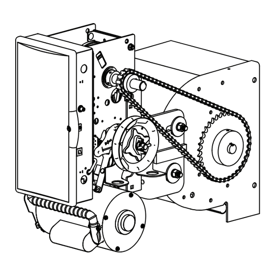
GCL-J
Standard Duty Operator
JACKSHAFT/HOIST
PROPER APPLICATION
Door Type Operator Type HP/Max Door Weight HP/Max Door Weight
ALL TYPES Jackshaft/Hoist
Commercial / Industrial Door Operator.
™
H
™
&
MultiVolt®
EZ Limit®
TensiBelt®
(Sectional)
1/2HP = 1120 lbs
Hood Mount or
3/4HP = 1370 lbs
Wall Mount
1HP = 1620 lbs
111845.502351 04-14
(Rolling Steel)
1/2HP = 998 lbs
3/4HP = 1220 lbs
1HP = 1440 lbs
Advertisement
Table of Contents


Need help?
Do you have a question about the GCL-J&H 1/2HP and is the answer not in the manual?
Questions and answers