Genie GCL-GH Installation Manual
Heavy duty operator hoist
Hide thumbs
Also See for GCL-GH:
- Installation supplement manual (8 pages) ,
- Specifications (2 pages) ,
- Product manual (2 pages)
Table of Contents
Advertisement
N O T F O R R E S I D E N T I A L U S E
This Installation Manual provides the information required to install, troubleshoot and
maintain a GCL-GH
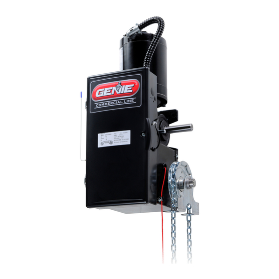
GCL-GH
Heavy Duty Operator
HOIST
WITH EXCLUSIVE FEATURES:
PROPER APPLICATION
Door Type
Operator Type
Sectional
Hoist
(All Types)
(Side/
Centermount)
Rolling Steel
Hoist
(All Types)
(F
Wall Mount)
™
C
o
m
m
e
™
Multivolt®
EZ Limit®
HP/Max Door Weight
1/2HP = 1310 lbs.
3/4HP = 1450 lbs.
1HP = 1650 lbs.
3HP = 3696 lbs.
ront of Hood or
c r
a i
/ l
n I
d
s u
r t
l a i
D
o
111837.501539
r o
O
p
e
a r
o t
. r
06-12
Advertisement
Table of Contents

Related Manuals for Genie GCL-GH


Summary of Contents for Genie GCL-GH
- Page 1 Wall Mount) N O T F O R R E S I D E N T I A L U S E This Installation Manual provides the information required to install, troubleshoot and maintain a GCL-GH ™ l a i...
-
Page 2: Table Of Contents
Warranty ......... 11.1 Monitored Reversing Devices ......6.10 GCL-GH www.geniecompany.com... -
Page 3: How To Use This Manual
Details important features and troubleshooting information for typical installation and normal operations that may occur. Sections 9-11 Provides related information on service and maintenance items, operator drawings for use in troubleshooting and service activities, along with important warranty and returned goods policy information. GCL-GH www.geniecompany.com 06-12 Heavy Duty Operator... -
Page 4: Safety Information & Instructions
2. Keep the door in good working condition. Periodically lubricate all moving parts of door. To call a local Genie® Dealer, dial 800-OK-GENIE. For Genie® Technical Service, call 800-843-4084. 3. If door has a sensing edge, check In this Manual, the words Danger, Warning, and Caution are used to stress important safety information. The word: operations monthly. -
Page 5: Critical Installation Information
MillerEdge ME, MT and series monitored edge sensors used in combination with Timer-Close Module P/N OPABTCX.S or OPAKMEIX.S INTERFACE MODULE. 2) Residential Safe-T-Beam® Monitored Photocells from The Genie® Company, model OSTB-BX (P/N 38176R). 2) Series II Commercial Safe-T-Beam®, Monitored Photocells P/N OPAKPE.S. - Page 6 22GA. 24GA. 26GA. 18GA. 20GA. 22GA. ALUM. STL/SST GCL-GH GCL-GH GCL-GH 1035 1152 1152 1152 GCL-GH Note: Total door weight and not square footage is the critical factor in selecting the proper operator. These Sq.Ft. measurements are based on square doors, e.g. 16' x 16'.
-
Page 7: Installation Instructions
7) Install the Entrapment Warning Placard next to the control station and in a prominent location. 8) For products having a manual release, instruct the end user on the operation of the manual release. GCL-GH www.geniecompany.com 06-12 Heavy Duty Operator... -
Page 8: Installation
(Typical mounting arrangements shown in figures 1 and 2.) 13 5/16" 5 1/8" "A" DIM 4 1/4" 15 1/2" 3 1/2" 4 5/16" TO HEADPLATE (OPERATOR SIDE Figure 2 Figure 1 ROOM REQ'D.) 14 5/8" (WIDTH OF OPERATOR) GCL-GH www.geniecompany.com 06-12 Heavy Duty Operator... - Page 9 (These are in addition EDGE OF to the slotted mounting holes.) OPENING Figure 5 5 " (1/2, 3/4, 1HP) Optional Bracket " Figure 7 (1/2, 3/4, 1HP) GCL-GH www.geniecompany.com 06-12 Heavy Duty Operator...
-
Page 10: Chain Couple
To Complete the Installation: Figure 4B If needed, realign operator sprocket with door sprocket. If you have excessive door shaft movement, an optional chain tension plate is available , pg 4.4. Figure 4C GCL-GH www.geniecompany.com 0 -12 Heavy Duty Operator... - Page 11 5) Tighten and align chain and plate and secure operator to wall. 6) Tighten spreader bracket bolts. SPROCKET DOOR SHAFT GOES ON FIRST SPROCKET OPERATOR GOES ON LAST SHAFT Figure 5A Figure 5B GCL-GH www.geniecompany.com 0 -12 Heavy Duty Operator...
- Page 12 5) Loop chain around keeper as shown. Fig. 12. Optional Padlock not provided. NOTE: To insure smooth operation, make sure there is no twist in the hand chain before connecting the link ends together. GCL-GH www.geniecompany.com 06-12 Heavy Duty Operator...
- Page 13 Door may not be operating freely or counter-balance spring may need adjusting. Repairs and adjustments must be performed by a trained service representative using proper tools and instructions. Figure 13 ADJUSTMENT BOLTS GCL-GH www.geniecompany.com 06-12 Heavy Duty Operator...
-
Page 14: Wiring
(Right & Left) • Keep low voltage and line voltage wires separate. • Route all line voltage wires as shown. ROUTE HIGH VOLTAGE WIRING IN THE SHADED AREA AS SHOWN • Plug all unused conduit holes. GCL-GH www.geniecompany.com 06-12 Heavy Duty Operator... -
Page 15: Low Voltage Control Wiring
See Figs 2 through 10 in this section. Optional Accessory VOLTAGE • Plug all unused conduit holes. Modules INPUT PLUGS (Left & Right) Figure 2 LOW VOLTAGE CONTROL WIRE TERMINALS GCL-GH www.geniecompany.com 06-12 Heavy Duty Operator... -
Page 16: External Wire Diagram
REQUIRE THE THRU-BEAM PHOTOCELLS STOP BUTTON TO BE WIRED SERIES II SAFE-T-BEAM ® SIGNATURE IN SERIES. MODULE (STB) See Fig. 5, pg 5.4 CONNECT STB WIRES TO EITHER TERMINAL) 2-WIRE MONITORED SENSING EDGE SWITCH GCL-GH www.geniecompany.com 06-12 Heavy Duty Operator... -
Page 17: Wall Control
NOTE: Long Distance Relay Kit wiring is not required for long OPEN OPEN distance control runs and should not be used. SWTCH CLOSE CLOSE STATION STOP STOP CARD READER 3-BUTTON 3-BUTTON STATION STATION OPEN/CLOSE PULL SWTCH GCL-GH www.geniecompany.com 06-12 Heavy Duty Operator... -
Page 18: Interlock Switches
TERMINALS MUST BE REMOVED. 405964-0000 Switches must be set in the field. Figure 6 SWITCH 110325.0001 STANDARD Side lock interlock: (N.C.) SLIDELOCK Should be open when door is locked. TRACK Closed when door is unlocked. GCL-GH www.geniecompany.com 06-12 Heavy Duty Operator... - Page 19 T o p o voltage range. f l e n s t o f l o o r . NOTE: If no voltage is present at Blue wire, check fuse F-1 on Control board. Figure 9 GCL-GH www.geniecompany.com 06-12 Heavy Duty Operator...
-
Page 20: Sensing Edge Switch
• Check sensing edge switch for proper operation. WARNING: SENSING Actuating the operator using constant contact on the CLOSE EDGE button will override external reversing devices, including sensing edges or JUNCTION BOX reversing edges. GCL-GH www.geniecompany.com 06-12 Heavy Duty Operator... -
Page 21: External Radio (Optional)
“EXT RAD.” Fig. 12. 2) Make wiring connections to the wires per the diagram below. Optional Accessory Modules EXTERNAL 20-40 VDC @ 250mA RADIO MAX CURRENT CONNECTOR EXT RADIO CONNECTOR RELAY + 24VDC Figure 12 RADIO GCL-GH www.geniecompany.com 06-12 Heavy Duty Operator... -
Page 22: Connecting Motor/Safety Instructions
7) SAVE THESE INSTRUCTIONS. 480/ 208/ 240V 575V THREE PHASE DANGER After power is supplied to the operator, Do Not make contact with components inside the control panel except for the Keypad Keys. Fig. 1. GCL-GH www.geniecompany.com 06-12 Heavy Duty Operator... - Page 23 Appendix D. WARNING DO NOT calibrate operator or Figure 1 operate door unless doorway is in sight and free of obstructions. Door will move during setup. Keep people clear of opening while door is moving. GCL-GH www.geniecompany.com 06-12 Heavy Duty Operator...
- Page 24 Verify close mode is set to “C-STP”and NOT “C-REV”or “MOM” before continuing. 5) Press CAL/RUN to return to run mode. Figure 4 IDLE DOWN LIMIT CLOSE MODE C-STP Door closed - operator standing by Figure 5 Figure 2 GCL-GH www.geniecompany.com 06-12 Heavy Duty Operator...
-
Page 25: Setting Braking Rate
4) Pick a value and operate the door. Adjust as necessary. 5) Press a SCROLL key to shift to a new function and lock in the setting. SCROLL SCROLL CLEAR 6) Press CAL/RUN to return to run mode. SCROLL Figure 6 GCL-GH www.geniecompany.com 06-12 Heavy Duty Operator... -
Page 26: Setting Travel Limits
OPEN CLOSE desired height. STOP 5) Press SET/CLEAR to switch display to ”UP LIMIT>SET” or CLEAR SCROLL ”DOWN LIMIT>SET” CLEAR 6) Press CAL/RUN to return to run mode. SCROLL Figure 8 GCL-GH www.geniecompany.com 06-12 Heavy Duty Operator... -
Page 27: Setting Up Limit Overrun
9, Reset the Limit Overrun back to 0 and reset the Down Limit position as described on pg. 6.3. Then adjust the Limit Overrun as instructed above. 7) Press CAL-RUN to return to run mode. GCL-GH www.geniecompany.com 06-12 Heavy Duty Operator... -
Page 28: Setting Open & Close Modes
“CLOSE MODE>C-REV” or ”CLOSE MODE>MOM” on the display. 4) Press a SCROLL key to shift to a new function and lock in the setting. SCROLL Figure 10 5) Press CAL/RUN to return to run mode. GCL-GH www.geniecompany.com 03-12 Heavy Duty Operator... -
Page 29: (Optional) Transmitter Programming
(up or down) to move on to another menu item, 5) Press SCROLL CROLL (up or down) to move on to another menu item, or CAL/RUN to exit the CAL mode. or CAL/RUN to exit the cal mode. GCL-GH www.geniecompany.com 03-12 Heavy Duty Operator... -
Page 30: (Optiional) Mid-Stop Limit Setting
3) Press S CROLL until display reads “MID-STOP SCROLL SC L C O E CL SE MID-STOP > CLR” 5) Press S ET/CLEAR until the display reads ” CLEAR Press CAL/RUN to return to run mode. GCL-GH www.geniecompany.com 03-12 Heavy Duty Operator... -
Page 31: Monitored Reversing Devices
2) MillerEdge ME and MT series monitored edge sensors used in combination with MillerEdge Signature Module SM-101. (Direct connect through STB inputs). 3) Safe-T-Beam® Monitored Photocells from The Genie® Company, P/N 38176R. 4) Series II Safe-T-Beam® Monitored Photocells P/N OPAKPE.S. 5) NEMA4 Series II Safe-T-Beam®, Monitored Photocells P/N OPAKPEN4GX.S. -
Page 32: Operator Cycle Count
This display will cycle between the version number of the current GDO STOP firmware and the current Display Firmware. 3) Press CAL/RUN to return to run mode. OPEN DISPLAY V# ####### CLOSE STOP Figure B SCROLL CLEAR GCL-GH www.geniecompany.com 03-12 Heavy Duty Operator... -
Page 33: Operator Type
This will display the current GDO type. 3) Press SET/CLEAR until display indicates correct GDO type SCROLL CLEAR CLEAR ( J-SHAFT or TROLLEY) SCROLL 4) Press CAL/RUN to return to run mode. Figure 3 GCL-GH www.geniecompany.com 03-12 Heavy Duty Operator... -
Page 34: Troubleshooting
The display will flash the number of the error code and SCROLL CLEAR the 2-digit error code followed by a description of the error code. Fig. 1 & 2. SCROLL Figure 2 GCL-GH www.geniecompany.com 03-12 Heavy Duty Operator... -
Page 35: Run Codes
These codes are displayed in calibration mode. The display will flash the number of the run code and the 2-digit run code followed by a description of the run code. Fig. 3 & 4. Figure 4 GCL-GH www.geniecompany.com 03-12 Heavy Duty Operator... - Page 36 The CLOSE wall button was then activated, causing the operator to close. While closing, the Normally-Open (N-O) Safety Input was activated, causing the operator to stop and then reverse, stopping at the up limit. Figure 5 GCL-GH www.geniecompany.com 03-12 Heavy Duty Operator...
-
Page 37: Led Indicators
Figure 6 TROUBLESHOOTING LED’s ENAB NORMALLY ON - STB ENABLED OFF - STB DISABLED ENABLE OFF - CHECK AC POWER SUPPLY + 24 VOLTS NORMALLY ON - POWER AVAILABLE CHECK FUSES GCL-GH www.geniecompany.com 03-12 Heavy Duty Operator... - Page 38 OVERHEAD DOOR CORPORATION USING CONSTANT CONTACT ON THE CLOSE BUTTON RECOMMENDS THAT LINE VOLTAGE WIRING BE PERFORMED WILL OVERRIDE EXTERNAL REVERSING DEVICES, BY A QUALIFIED ELECTRICIAN. SEE SECTION 5 FOR INCLUDING PHOTOCELLS. ADDITIONAL WIRING INSTRUCTIONS. GCL-GH www.geniecompany.com 03-12 Heavy Duty Operator...
-
Page 39: Service & Maintenance
EVERY 36 MO. MONTHLY 5,000 CYCLES 10,000 CYCLES 30,000 CYCLE MANUAL OPERATION OF DOOR PHOTOCELL/ SENSING EDGE OPERATION OPTIONAL CLUTCH ADJUSTMENT CHECK FOR LOSE OR MISSING HARDWARE CHECK LIMIT POSITION GEAR TRAIN WEAR * If Installed. GCL-GH www.geniecompany.com 03-12 Heavy Duty Operator... - Page 40 ELECTRICAL BOX COVER SEE PG 10.6 111602.0001 LIMIT ENCLOSURE ASSEMBLY BRAKE ENCLOSURE ASSEMBLY 111597.0001 BRAKE/RELEASE KIT 111861.0001.S NS=NOT SHOWN SEE SEPARATE PARTS BREAKDOWN (10.6) ** CONTACT DEALER FOR PROPER PART BASED ON YOUR SPECIFIC MODEL. GCL-GH www.geniecompany.com 03-12 10.1 Heavy Duty Operator...
- Page 41 WALL MOUNT BRACKET 111632.0001 LAG SCREW 086480.2416 HEX NUT (THROUGH 080340.0015 LOCK DOWN 086446.1216 SPROCKET ASSY HOLES) 080302.2626 FLAT WASHER BOLT 080105.0610 NS=NOT SHOWN ** CONTACT DEALER FOR PROPER PART BASED ON YOUR SPECIFIC MODEL. GCL-GH www.geniecompany.com 03-12 10.2 Heavy Duty Operator...
- Page 42 DOWEL PIN 111552.0001 BEVEL GEAR, 30T HOIST SHAFT 111529.0001 SPRING PIN 110313.0010 BEARING 110813.0001 FLAT WASHER 110819.0001 E-RING, .744” 111382.0003 NS=NOT SHOWN ** CONTACT DEALER FOR PROPER PART BASED ON YOUR SPECIFIC MODEL. GCL-GH www.geniecompany.com 03-12 10.3 Heavy Duty Operator...
-
Page 43: Motor Options
111697.0002—1HP, 1 PH, N4 111695.0002—1HP, 3 PH, TEFC 111696.0002—1/2HP, 3 PH, TENV 111697.0003—1/2HP, 3 PH, N4 111695.0003—1HP, 575V, TEFC 111696.0003—1HP, 3 PH, TENV 111697.0004—1HP, 3 PH, N4 111696.0004—1HP, 575V, TENV 111697.0004—1HP, 575V, N4 GCL-GH www.geniecompany.com 03-12 10.4 Heavy Duty Operator... - Page 44 SPRING 111555.0001 PINION GEAR (STANDARD) 111539.0001 111553.0001 BEVEL GEAR (3 HP) 111402.0001 THRUST BEARING THRUST WASHER 111403.0001 BRAKE RELEASE 111599.0001 NS=NOT SHOWN ** CONTACT DEALER FOR PROPER PART BASED ON YOUR SPECIFIC MODEL. GCL-GH www.geniecompany.com 03-12 10.5 Heavy Duty Operator...
- Page 45 INTERLOCK SWITCH 111781.0001.S ELECTRIC BOX COVER HINGE 110423.0001 111518.0001.S ELECTRIC BOX COVER BRACKET 111101.0001 MAIN CIRCUIT BOARD INSULATOR NS=NOT SHOWN ** CONTACT DEALER FOR PROPER PART BASED ON YOUR SPECIFIC MODEL. 35 2 GCL-GH www.geniecompany.com 03-12 10.6 Heavy Duty Operator...
-
Page 46: Electric Box Layout
Internal Radio Hoist Board Interlock 115V 460V 230V 1 PH Brake Connector 3 PH 1 PH 3 PH Motor Connector Connectors Motor Connectors Transformer Transformer Connectors Connectors Input Input Power Power Connectors Connectors GCL-GH www.geniecompany.com 03-12 10.7 Heavy Duty Operator... -
Page 47: Appendix C
Causes moving door to stop. Prevents the operator from running. Hoist Interlock Plug or Jumper. HOIST INTLK Operates even if microcontroller is non-functional. LIMIT SENSOR Causes door to stop at top and bottom of normal travel. Limit Sensor Plug. GCL-GH www.geniecompany.com 03-12 10.8 Heavy Duty Operator... -
Page 48: Run Codes
GDO REVERSED BECAUSE THE AUXILIARY OPEN INPUT WAS ACTIVATED REV > OPEN KEY GDO REVERSED BECAUSE THE KEYPAD OPEN KEY WAS ACTIVATED REV > N-O SAFETY GDO REVERSED BECAUSE THE N-O REVERSING INPUT WAS ACTIVATED GCL-GH www.geniecompany.com 03-12 10.9 Heavy Duty Operator... - Page 49 GDO WON'T RUN BECAUSE ITS AT OR ABOVE THE MID-STOP LIMIT & CAN'T RUN UP & A REVERSING INPUT IS PREVENTING IT FROM CLOSING EXP MODULE FAIL GDO WON'T RUN BECAUSE AN EXPANSION MODULE FAILURE IS PREVENTING IT GCL-GH www.geniecompany.com 03-12 10.10...
-
Page 50: Error Codes
OPENING FROM TRANSMITTER # __ CLOSING > XMTR # CLOSING FROM TRANSMITTER # __ HALT > XMTR # HALT FROM TRANSMITTER # __ NO XMTR > CC NO CONTROL FROM TRANSMITTER, CONSTANT CONTACT EMPLOYED AT LOCAL CONTROL GCL-GH www.geniecompany.com 03-12 10.11 Heavy Duty Operator... - Page 51 GCL-GH www.geniecompany.com 03-12 11.1 Heavy Duty Operator...
- Page 52 One Door Dr. Mt. Hope, OH 44660...
Need help?
Do you have a question about the GCL-GH and is the answer not in the manual?
Questions and answers