Table of Contents
Advertisement
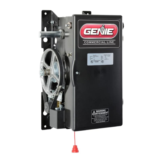
GCL-MJ & MH
Medium Duty Operator
For Z Series MODELS
OPGMZJ5011B & OPGMZH5011BL/BR
Sidemount Operator
APPLICATIONS:
Jackshaft/Hoist Operators can be assembled in the following configurations:
• Chain Couple
Jackshaft/Hoist Operators can be installed on the following types of doors up to 16 feet high:
• Sectional Doors - Vertical Lift, Lift Clearance Type
• Rolling Steel Doors
HP/Max Door Weight/Height:
• Sectional - 1/2 HP Only - 620lbs/16 ft.
• Rolling Steel - 1/2 HP Only - 580lbs/16 ft.
This installation manual provides the information required to install,
113072.00231
NOT FOR RESIDENTIAL USE
program, troubleshoot and maintain a
GCL-MJ & GCL-MH operator.
09/2021
Advertisement
Table of Contents

Related Manuals for Genie GCL-MJ


Summary of Contents for Genie GCL-MJ
- Page 1 • Sectional - 1/2 HP Only - 620lbs/16 ft. • Rolling Steel - 1/2 HP Only - 580lbs/16 ft. NOT FOR RESIDENTIAL USE This installation manual provides the information required to install, program, troubleshoot and maintain a GCL-MJ & GCL-MH operator. 113072.00231 09/2021...
-
Page 2: Table Of Contents
INDEX SECTION 1: General Information & Instructions General Information & Instructions ........................1.1 Safety Information & Instructions ........................1.2-1.3 Critical Installation Information - General ......................1.4 Critical Installation Information - Entrapment Protection ................1.5 SECTION 2: Operator Installation Sectional Sidemount Installation ........................2.1-2.2 Rolling Steel Installation ............................. -
Page 3: General Information & Instructions
Section 1: General Information & Instructions Job Site Issues to Consider/Concerns The following list of items should be considered prior to selecting an operator for a given job site. 1. Available power supply. 2. Type of door. 3. Potential operator mounting obstructions. Items to consider include, but are not limited to: Room above door shaft, room below door shaft, available mounting surface integrity, power supply location, and convenient release cable positioning. -
Page 4: Safety Information & Instructions
Since moving objects, springs under tension, and electric motors can cause injury, your safety and the safety of others depend on you reading the information in this manual. If you have any questions or do not understand the information presented, call your nearest service representative. For the number of your local Genie Dealer, call 800-OK-GENIE. - Page 5 Pour obtenir le numéro du revendeur Genie local, appelez le +1 (800) OK-GENIE. Dans ce manuel, les mots Danger, Avertissement, et Attention sont utilisés pour faire ressortir d’importantes informations relatives à...
- Page 6 Section 1: Critical Installation Information IMPORTANT INSTALLATION INSTRUCTIONS WARNING To reduce the risk of severe injury or death: READ AND FOLLOW ALL INSTALLATION INSTRUCTIONS. Install only on a properly operating and balanced door. A door that is operating improperly could cause severe injury.
- Page 7 Section 1: Critical Installation Information IMPORTANT INSTALLATION INFORMATION ENTRAPMENT PROTECTION: The installation of a monitored fail safe external reversing device is required on all momentary contact electronically operated commercial doors. If such a reversing device is not installed, the operator will revert to a constant contact control switch for close operation.
- Page 8 Section 2: Sectional Operator Installation Chain Couple: The GCL-MJ & MH operators can be ordered for right or left hand mounting above or below the door shaft. FIG. 1. Hoist operators must be ordered for left or right handing from the factory.
- Page 9 Section 2: Sectional Operator Installation Complete the Installation If needed, realign operator sprocket with door sprocket. If you have excessive door shaft movement, an optional chain tension bracket is available. Chain Tension Bracket: Bracket is available as an optional kit for 1 inch door shafts, P/N 111005.0001.S Installation of optional chain spreader bracket: FIG 1 .
- Page 10 Section 2: Rolling Steel Operator Installation Rolling Steel/Grill Doors. FIG. 1 Front of Hood: The rolling steel door operator is configured at the factory for right-hand or left-hand (Hoist & Jackshaft) Front of Hood. 1. Mounting hardware and instruction will be supplied based on door specifications. (Typical mounting arrangements shown.) 2.
- Page 11 Section 2: Rolling Steel Operator Installation Hand Chain & Keeper: 1. Route the hand chain through the chain guide, around the pocket wheel and back through the chain guide. FIG.1. 2. Connect the hand chain ends together as shown in FIG. 2. by twisting open the last link on one end of the chain, and slipping the last link on the opposite end onto the open link.
-
Page 12: Section 2: Operator Installation
5 feet from floor. Clutch Adjustment: The GCL-MJ & MH operators have a friction-style clutch that needs to be adjusted. NOTE: The clutch is intended to provide protection for the door, the operator and associated equipment. It is not intended for entrapment protection. -
Page 13: Section 3: Operator Wiring
Section 3: Wiring WARNING • DO NOT apply power to operator until instructed to do so. • It is strongly recommended, and may be required by law in some areas, that line voltage wiring be performed by a qualified electrician. • Be sure that electrical power has been disconnected from the input power wires being connected to the operator prior to handling these wires. - Page 14 Section 3: Wiring Sec-3.2...
-
Page 15: Line Voltage
Section 3: Wiring Line Voltage Wiring: 1. Remove line voltage input plug and install proper fittings and 1/2” conduit. 2. Route proper line voltage wires into operator. 3. Locate line input terminals on circuit board. Using correct connectors, attach wires to line inputs, and ground terminal. -
Page 16: Low Voltage
Section 3: Wiring Low Voltage Control Wiring: 1. Connect all low voltage control circuit wires using 1/2” conduit or flexible convoluted tubing. • Keep low voltage and line voltage wires separate. • Route all low voltage control wiring as shown. This includes all control circuit wires such as wall controls, interlock switches and single button input devices as well as safety circuit wiring. -
Page 17: Wall Controls
Section 3: Wiring Wall Controls: WARNING • Wall Control(s) must be located so that the door is within sight of the user and is far enough from the door, or positioned such that the user is prevented from coming in contact with the door while operating controls. - Page 18 Section 3: Wiring 1. For a single open/close/stop installation, make connections as shown in FIG. 1. 2. For single button accessory controls, make connections as shown in FIG. 2. 3. For a multiple open/close/stop installations, make connections as shown in FIG. 3. 4.
- Page 19 Section 3: Wiring External Accessories: Interlock Switches: If a slide lock is required on the door for pass-through doors or other requirements, an interlock will be required to prevent the opener from running when engaged. Install a Normally Closed interlock switch and wire directly to the operator.
-
Page 20: Interlocks
Section 3: Wiring Interlock Switches: Optional external interlock switches are required with some doors to prevent the door from operating under certain conditions including the following: • If the door is equipped with a functioning door lock, an interlock switch (A) must be installed to prevent electric operation when the lock is engaged. -
Page 21: Photocells
Section 3: Wiring Photocells: WARNING Actuating the operator by using constant contact on the CLOSE button will override non-functioning external reversing devices, including photocells. AVERTISSEMENT L’activation de l’operateur en util isant un contact constant sur le bouton FERMER annulera les dispositifs d’inversions externes, y compris les cellules photoelectriques. - Page 22 Section 3: Wiring Photocells: CONNECT WIRES TO EITHER TERMINAL. Monitored Type Photocells (NOT POLARITY SENSITIVE) CONTROL SIGNAL TERMINAL STRIP RESIDENTIAL SAFE-T-BEAM® (STB) 20-40 VDC @ 250mA MAX. CURRENT FIG. 5 EXT RADIO CONNECTOR CONTROL SIGNAL TERMINAL STRIP SAFETY SAFETY Non-Monitored Type Photocells RELAY + 24VDC RADIO...
- Page 23 Section 3: Wiring Monitored Edges, Hardwired: WARNING Actuating the operator by using constant contact on the CLOSE button will override non-functioning external reversing devices, including sensing edges. AVERTISSEMENT L’activation de l’operateur en util isant un contact constant sur le bouton FERMER annulera les dispositifs d’inversions externes, y compris les systèmes de détection des bords.
- Page 24 Section 3: Wiring Monitored Edges, Wireless: WARNING Actuating the operator by using constant contact on the CLOSE button will override non-functioning external reversing devices, including sensing edges. AVERTISSEMENT L’activation de l’operateur en util isant un contact constant sur le bouton FERMER annulera les dispositifs d’inversions externes, y compris les systèmes de détection des bords.
-
Page 25: Sensing Edge, Hardwire With Expansion Board
Section 3: Wiring Sensing Edges, Hardwired with Expansion Board: WARNING Actuating the operator by using constant contact on the CLOSE button will override non-functioning external reversing devices, including sensing edges. AVERTISSEMENT L’activation de l’operateur en util isant un contact constant sur le bouton FERMER annulera les dispositifs d’inversions externes, y compris les systèmes de détection des bords. - Page 26 Section 3: Wiring Non-Monitored Safety Edge: WARNING Actuating the operator by using constant contact on the CLOSE button will override non-functioning external reversing devices, including sensing edges. AVERTISSEMENT L’activation de l’operateur en util isant un contact constant sur le bouton FERMER annulera les dispositifs d’inversions externes, y compris les systèmes de détection des bords.
- Page 27 Section 4: Programming Apply Power To Operator: DANGER After power is supplied to the operator, Do Not make contact with components inside the control panel except for the Keypad Keys. DANGER Après avoir mis l’opérateur sous tension, NE PAS entrer en contact avec des composants à l’intérieur du panneau de commande, sauf pour les touches du pavé...
- Page 28 Section 4: Programming Calibration Mode Structure: If at any time should programming become confused. Press the CAL/RUN key once to enter RUN MODE then press CAL/RUN key again to re-enter CALIBRATION MODE. Press the SCROLL key(s) to locate or check the settings on any menu item. Operator Calibration Menu Structure 1.
-
Page 29: Close Direction
Section 4: Programming Setting Close Direction: The direction of motor rotation depends on mounting position and/or how the main input power phases are wired. This setting is used to ensure the door is closing and opening according to the input commands. NOTE: Make sure door is in mid-travel. -
Page 30: Travel Limits
Section 4: Programming Setting Travel Limits: 1. If operator is in RUN mode, press CAL/RUN key to enter CALIBRATION MODE. 2. Use the SCROLL Key to scroll through the menu until UP LIMIT > CLR is displayed. 3. Jog the door using the OPEN key until you reach the desired height. 4. -
Page 31: Limit Overrun
Section 4: Programming Setting Limit Overrun: WARNING The Limit Overrun will override external reversing devices, including photocells and sensing edges or reversing edges. Therefore, any externally connected devices will be disabled during that portion of the door travel controlled by the Limit Overrun function. The Down Limit Overrun function should be used to close the door no more than the final 2”. -
Page 32: Monitored Reversing Devices
Section 4: Programming Monitored Reversing Devices WARNING Photocell systems provide entrapment protection when mounted near the doorway in such a way that the lower portion of an individuals leg will break the photocell beam during normal walking through the doorway. AVERTISSEMENT Les systèmes de cellules photoélectriques fournissent une protection contre le coincement s’ils sont installés à... - Page 33 Section 4: Programming Setting Open and Close Modes (Constant vs. Momentary Contact) WARNING Before momentary contact control can be used on the CLOSE button, a monitored external reversing device such as a photocell system or sensing edge switch must be used. See WIRING SECTION for installation of entrapment protection devices.
- Page 34 Section 4: Programming Adding a Transmitter 1. If operator is in RUN mode, press CAL/RUN to enter CALIBRATION MODE. 2. Press SCROLL (up or down) until display reads LEARN NEW XMTR? FIG. 1. • This question along with the instruction HIT SET FOR YES will continuously pan across the display window.
-
Page 35: Mid-Stop
Section 4: Programming Mid-Stop Limit (Optional) NOTE: Setting of the MID-STOP should only be performed AFTER the travel limits and max run timer settings have been made. 1. If operator is in RUN mode, press CAL/RUN to enter CALIBRATION MODE. 2. -
Page 36: Max Run Timer
Section 4: Programming Resetting the MRT (Max Run Timer) CAUTION The MID-STOP feature must be turned off in order to properly set the Max Run Timer. ATTENTION La fonction MID-STOP doit être désactivée afin de régler correctement la minuterie de course maximum. NOTE: The Max Run Timer is set automatically once the unit is cycled between limits. - Page 37 Section 4: Programming Operator Cycle Count 1. Press CAL/RUN to enter CALIBRATION MODE. 2. Press SCROLL until display reads CYCLES>1,2,3 etc. where the number shown is the number of open/ close cycles the operator has performed. FIG. 7. 3. Press CAL/RUN to return to RUN mode. OPEN CYCLES CLOSE...
-
Page 38: Gdo Type
Section 4: Programming GDO and Display Firmware 1. Press CAL/RUN to enter CALIBRATION MODE. 2. Press SCROLL until display reads GDO V# > #####. FIG. 8. • This display will cycle between the version number of the current GDO firmware and the current display firmware. -
Page 39: Section 5: Troubleshooting
Section 5: Troubleshooting GCL-MJ-MH operators include a self-diagnostic circuit board using troubleshooting LED indicators to signal the technician of a problem. TROUBLESHOOTING LEDs ENAB + 24 ENAB '< ./& ./& 000-C.0 000-C.0 00"2, 00"2, .1"- &'.5" 5,.1 <B$,- + 24 5)8",9... - Page 40 Section 5: Troubleshooting Display Operation in RUN Mode This operator will display its status on the integrated display. Each time the operator runs, stops, reverses or refuses to run, the display will indicate the operating action, what device initiated the action, and any error condition that prevented/impacted the intended operation.
- Page 41 Section 5: Troubleshooting RUN CODES Code Display Detailed/Expanded Description Corrective Action IDLE > DOWN LIMIT The door is at the Down Limit position. None IDLE > UP LIMIT The door is at the Up Limit position. None IDLE > MID STOP The door is at the Mid-Stop Limit position.
-
Page 42: Error Codes
Section 5: Troubleshooting Error Codes To aid in troubleshooting problems, this operator includes an error code memory that stores the most recent 10 error events. These codes are stored with or without power. The latest error code detected is also displayed on the lcd until the stop button or key is pressed or the operator stops at the down limit. - Page 43 Section 5: Troubleshooting Code Display Detailed/Expanded Description Corrective Action REV > MAX RUN TMR The door stopped traveling down and reversed because the Check the door balance. Check the Clutch adjustment to Maximum Run Time between Limits was exceeded. make sure it's not slipping. Re-record the Max Run Timer values in both directions.
- Page 44 Section 5: Troubleshooting Code Display Detailed/Expanded Description Corrective Action CHECK N-C SAFETY The unit will not close because it determined the Normally Check the Normally Close (N-C Safe) Input device wired Closed Reverse input on the Timer Close Module is active into the Timer Close Module and device wires for an open (Open circuit).
- Page 45 Section 5: Troubleshooting Code Display Detailed/Expanded Description Corrective Action LIMIT MOD. FAIL The unit has determined that the Limit Module has stopped Check the limit cable connection. Power the unit down communicating. and back up. If the error persist then replace the Limit Module.
-
Page 46: Section 6: Service & Maintenance
Section 6: Service & Maintenance The following table provides a schedule of recommended Service and Maintenance items to be completed by qualified service personnel. CAUTION Failure to perform the recommended Service & Maintenance may result in premature failure of the operator. - Page 47 Section 6: Service & Maintenance HOIST ELECTRIC BOX BILL OF MATERIAL PART NO. DESCRIPTION ITEM NO. 113125-0001 KIT, ENCLOSURE, MZ 111010-0001 BELT, POLY-V, STRETCH 111421-0003 LIMIT MODULE, X-SERIES, AK 113055-0048 CHAIN, #410 X 48P, LOOP 113068-0002 BRAKE ASSY, HOIST, MZ 113058-0002 SHAFT ASSY, OUTPUT, DC/IC, MZ 113057-0003...
- Page 48 Section 6: Service & Maintenance JACKSHAFT ELECTRIC BOX BILL OF MATERIAL PART NO. DESCRIPTION ITEM NO. 113125-0001 KIT, ENCLOSURE, MZ 111010-0001 BELT, POLY-V, STRETCH 111421-0003 LIMIT MODULE, X-SERIES, AK 113055-0048 CHAIN, #410 X 48P, LOOP 113068-0001 BRAKE ASSY, TROLLEY/JACKSHAFT, MZ 113058-0002 SHAFT ASSY, OUTPUT, DC/IC, MZ 113057-0002...
- Page 49 Section 6: Service & Maintenance 2.0 AMP (FUSE WITH GREEN DOT) .315 AMP (FUSE WITH YELLOW DOT) BILL OF MATERIAL PART NO. DESCRIPTION ITEM NO. 113033.0001 BOX, ELECTRIC, MZ 110846.0001 XFMR, 120V 110950.0001 HINGE, ELECTRIC BOX 19988A CAPACITOR,70 MFD 111851.0002 COVER, ELECTRIC BOX, BLACK 111397.0001 RCVR ASSY, 315/390,...
- Page 50 JACKSHAFT CLUTCH SHAFT 14 3 11 7 2 18 8 11 HOIST CLUTCH SHAFT HOIST/JACKSHAFT OUTPUT SHAFT JACKSHAFT CLUTCH SHAFT - 113057.0002 HOIST CLUTCH SHAFT - 113057.0003 HOIST/JACKSHAFT OUTPUT SHAFT - 113058.0002 BILL OF MATERIAL BILL OF MATERIAL BILL OF MATERIAL PART NO.
- Page 51 Commercial Operator Limited Warranty The Genie Company (“Seller”) warrants to the original purchaser of the GCL-MH/MJ commercial door operator (”Product”), subject to all of the terms and conditions hereof, that the product and all components thereof will be free from defects in materials and workmanship under normal use for the following period(s), measured from the date of installation.
- Page 52 The Genie Company 1 Door Drive, Mount Hope, OH. 44660 1-800-843-4084 www.geniecompany.com...
Need help?
Do you have a question about the GCL-MJ and is the answer not in the manual?
Questions and answers