Emerson E2 Installation And Operation Manual
For rx refrigeration, bx hvac, and cx convenience store controllers
Hide thumbs
Also See for E2:
- Installation and operation manual (51 pages) ,
- User manual (34 pages) ,
- Manual (21 pages)

Related Manuals for Emerson E2


Summary of Contents for Emerson E2
- Page 1 026-1614 Rev 4 5-JAN-2013 E2 Installation and Operation Manual for RX Refrigeration, BX HVAC, and CX Convenience Store Controllers Applicable to E2 firmware versions 4.0 and above...
- Page 3 CE COMPLIANCE NOTICE Class A Product Information for E2 Controllers: The Emerson Retail Solutions Einstein and E2 controllers are Class A products. In a domestic environment this product may cause radio interference in which case the user may be required to take adequate measures. This covers: All E2 family product types: RX - Refrigeration Controller (845-xxxx), ...
-
Page 5: Table Of Contents
TABLE OF CONTENTS 1 INTRODUCTION..............................1-1 1.1 T E2 R (RX)......................1-1 EFRIGERATION ONTROLLER 1.2 T E2 B (BX)........................1-2 UILDING ONTROLLER 1.3 T E2 C (CX)....................1-3 ONVENIENCE TORE ONTROLLER 1.4 N ............................1-4 ETWORKING VERVIEW 1.4.1 E2 I/O Network ..............................1-4 1.4.2 The E2 Echelon Lonworks Network........................ - Page 6 3.3 E ..............................3-5 CHELON EVICES 3.3.1 CC-100 Case Controller and CS-100 Case Circuit Controller ................. 3-5 3.3.2 MultiFlex ESR ..............................3-5 3.3.3 TD3..................................3-5 3.4 COM3 I NTERNAL ODEM (P/N 638-3362).................................. 3-5 3.4.1 Two-Channel and Four-Channel Repeaters ...................... 3-6 3.4.1.1 Mounting Repeaters Overview ..........................
- Page 7 4.3.4 Plug-In Digital I/O Network Card (P/N 638-4880)................... 4-3 4.3.4.1 LEDs ..................................4-3 4.3.5 Plug-In Four-Channel Internal Repeater ......................4-3 5 SERIAL CONFIGURATION ........................... 5-1 5.1 O ................................. 5-1 VERVIEW 5.2 COM P ................................5-1 ORTS 5.3 S ........................5-1 ERIAL EVICE AND OFTWARE...
- Page 8 6.4.3.1 Add and Connect a BACnet Device ........................6-14 7 E2 ETHERNET PEER COMMUNICATIONS ...................... 7-1 7.1 E IP C ..........................7-1 THERNET ONFIGURATIONS 7.2 H ............................. 7-1 ARDWARE PECIFICATIONS 7.2.1 Components................................ 7-1 7.3 S ............................7-2 OFTWARE PECIFICATIONS 7.4 E ..........................
- Page 9 9.3.3 Valve Cable ..............................9-17 9.4 CCB C ............................9-18 ONTROLLERS 9.5 ESR8 ESR V ................... 9-18 ULTI ALVE UTPUT IRING 10 QUICK START..............................10-1 10.1 L ................................. 10-1 OGGING 10.2 C ........................10-1 LEANING UT THE ONTROLLER 10.3 S ......................
- Page 10 10.17.1 Priority Settings............................10-24 10.18 S ............................10-25 PPLICATIONS 10.18.1 Add/Delete an Application ......................... 10-26 10.18.2 Using and Configuring a Setup Screen ...................... 10-26 10.18.2.1 The Edit Menu ..............................10-27 10.18.2.2 Entering Setpoints............................10-27 10.18.2.3 Navigating the Setup Screen..........................10-27 10.18.3 Using the Help Key to get Property Help ....................
- Page 11 11.4.3 Refrigeration Control........................... 11-11 11.4.3.1 EEVs (Liquid Pulse and Liquid Stepper)......................11-11 11.4.3.2 EEPRs (Suction Stepper) ........................... 11-12 11.4.4 Defrost Control ............................11-12 11.4.4.1 Defrost States ..............................11-12 11.4.4.2 Defrost Types..............................11-12 11.4.4.3 Defrost Termination............................11-13 11.4.4.4 Demand Defrost ..............................11-13 11.4.4.5 Emergency Defrost ............................
- Page 12 11.7.2 How Zones Work ............................11-25 11.7.3 Applications That May Be Connected To Zones ..................11-26 11.7.3.1 MultiFlex RTU Board............................11-26 11.7.3.2 MultiFlex RCB Board............................11-26 11.7.3.3 AHUs ................................. 11-27 11.7.4 Temperature Control............................ 11-27 11.7.5 Zone Temperature ............................11-27 11.7.6 Economizer Control ............................. 11-27 11.7.7 Economization Enable..........................
- Page 13 11.13.1.3 Diagram................................11-41 11.13.2 Loop/Sequence Control Cell Descriptions....................11-41 11.13.2.1 The Select Cell..............................11-41 11.13.2.2 The Setpoint Float Cell ............................ 11-42 11.13.2.3 The PID Control Cell ............................11-42 11.13.2.4 The Filter Cell ..............................11-42 11.13.2.5 The Override Cell ............................11-42 11.13.3 Output Cell Descriptions ...........................
- Page 14 11.21.4.2 Volume................................11-52 11.21.4.3 Rain Delay ............................... 11-52 11.21.4.4 Freeze Lockout..............................11-52 11.21.4.5 Alarm ................................11-52 11.21.5 Zone Bypass Inputs............................. 11-52 11.21.5.1 Bypass Failsafe ..............................11-53 11.21.6 Flow Sensor-Related Tests ......................... 11-53 11.21.6.1 Leak Test................................11-53 11.21.6.2 Obstructed Zone Test............................11-53 11.21.7 Service Modes ............................
- Page 15 EATURE APPENDIX A: CASE TYPE DEFAULTS ........................ A-1 APPENDIX B: PRESSURE/VOLTAGE AND TEMPERATURE/RESISTANCE CHARTS FOR ECLIPSE TRANSDUCERS & EMERSON RETAIL SOLUTIONS TEMP SENSORS............B-1 APPENDIX C: ALARM ADVISORY MESSAGES....................C-1 COPELAND CORESENSE E2 ALARMS ......................C-15 APPENDIX D: PID CONTROL..........................D-1 APPENDIX E: COMPRESSED POINT LOG SAMPLE LIMITS AND PRECISION TABLE ......
-
Page 17: Introduction
Introduction The E2 controller is a microprocessor-based control fewer capabilities and a monochrome display. system designed to provide complete control of compres- The E2 RX is primarily designed to control tempera- sor groups, condensers, refrigerated cases, and other com- ture and defrost in refrigerated cases using either direct ponents related to refrigeration and building control. -
Page 18: The E2 Building Controller (Bx)
(AHUs), rooftop units (RTUs), and other systems related to environment control. In addition, the BX provides Capabilities extensive sensor control, logging, and graphing features that allow the user to view accurate real-time information ESR8 ESR Control about system conditions. The BX is equipped with many power monitoring and demand control features that give Flexible Combiner you the information you need to keep your site’s energy... -
Page 19: The E2 Convenience Store Controller (Cx)
the CX-300 and CX-400. Capabilities BX-300 BX-400 Holiday Schedule Capabilities HVAC Zone Infrared Leak Detec- Advanced Rooftop tion Control Lighting Control Logging Group Analog Combiner Loop/Sequence Control Analog Sensor Control MRLDS Anti-Sweat Power Monitoring Case Control Circuit Pulse Accumulator CC100 Case Suction RCB/RCB-P Controller CC100 Liquid Control RMS Asset... -
Page 20: Networking Overview
HVAC Zone The I/O Network is the same thing as the COM A and Infrared Leak Detec- COM D Networks found on Emerson Retail Solutions’ tion previous generation of controllers, REFLECS. This allows current owners of Emerson Retail Solutions’ Refrigeration... -
Page 21: The E2 Echelon Lonworks Network
E2s to provide logging, alarm control, and other functions. In addition to these, Emerson Retail Solutions also offers Echelon-compatible input and output boards similar to In large installations where more than one refrigeration those available for the RS485 Network. -
Page 22: Documentation Overview
II family, which includes the CUB-II and CUB-TD. Emerson Retail Solutions: • MultiFlex RTU Rooftop Controller Installation • E2 Installation and Operation Manual for RX and Operation Manual (P/N 026-1706) - Installa- Refrigeration, BX HVAC, and CX Convenience tion and operation guide for the MultiFlex RTU Store Controllers (026-1610) - The manual you are (replacement for ARTC). -
Page 23: On-Line Help System Overview
Solutions sales representative at 770-425-2724 for more stand-alone controller or in zone control applica- information about software licensing. tions using a Emerson Retail Solutions E2 BX building control system. The iPro DAC is capable of controlling heat and cool stages, fans, humidifi-... -
Page 25: Hardware Overview
Table 2-1 - E2 Specifications can be controlled, or more specifically, be turned on and off, such as compressors, condensers, lights, and fans. NOTE: Contact Emerson Emerson Retail Solutions Customer Service at 770-425-2724 for E2 controller part numbers and model de- scriptions. -
Page 26: E2 Main Processor Board (Cpu)
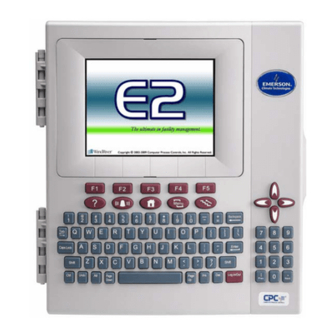
2.1.1 E2 Main Processor Board 2.1.3 E2 Keypad (CPU) Figure 2-4 - E2 Keyboard The E2 has a QWERTY style keyboard layout with two rows of function keys. The first row (-) is comprised of screen-specific function keys, and the sec- ond row has designated icon keys. -
Page 27: I/O Network Boards And Peripherals
RS485 devices depending on which type of Gateway is being used. The Gateway inter- faces devices to the Einstein/E2 and legacy Emerson Retail Solutions controller (REFLECS) by simulating 16AI and 8RO boards using Emerson Retail Solutions standard I/O board protocol. -
Page 28: Multiflex Boards
The MultiFlex 16 input board offers sixteen combina- Figure 2-7 - MultiFlex Combination Input/Output Board (Side tion analog/digital input points for use by Emerson Retail View) Solutions E2, Einstein, and REFLECS control systems. The MultiFlex 16 may be used in retrofits with no addi- tional hardware or software setup or upgrades. - Page 29 Table 2-7 shows the available models of MultiFlex combination input/output boards with description and part numbers. Model Description Name 810-3063 MultiFlex 8 analog/digital inputs, 8 re- 88AO lay outputs, 4 analog out- puts 810-3064 MultiFlex 8 analog/digital inputs, 8 re- lay outputs 810-3065 MultiFlex...
-
Page 30: Multiflex Cub
The compressor control strategy is Fixed either as a stand-alone controller or in zone control appli- Steps with setpoint/deadband using ON and OFF delays. cations using a Emerson Retail Solutions E2 BX building Up to 20 Fixed Steps can be configured. •... -
Page 31: The Multiflex Esr Board
13 Relay Status LED Board Status LEDs 14 Relay Fail-safe Switches The HHT can be used on any Emerson Retail Solutions (Code A, Code B, General Status) 15 PAK Analog Outputs 1-4 product with an RJ-11 connector. The most common appli-... -
Page 32: The 8Ro And 8Rosmt Relay Boards
E2. The 8RO board is easily installed and operated within the Emerson Retail Solutions Network environment because of its straightforward design. Several of these fea- tures are shown in Figure 2-13. -
Page 33: 4Ao Analog Output Board
3050). The 8DO has eight outputs which may pulse up to 150mA at 12VDC. Since the 8DO is primarily designed to control anti- sweat heaters, the 8DO is the heart of Emerson Retail Solutions’ Pulse Modulated Anti-Sweat Control (PMAC II) panel. The PMAC II (P/N 851-1000) provides 16 chan- nels of anti-sweat control circuitry. -
Page 34: Echelon Network Boards And Peripherals
Echelon Network 2.3.2 The 8ROe (Discontinued) Boards and Peripherals 2.3.1 The 16AIe (Discontinued) Figure 2-19 - 8ROe The 8ROe (P/N 810-4010) is an Echelon-based input board similar in function to its I/O Network counterpart, the 8RO. The 8ROe board is the direct link between the E2 and component operation. -
Page 35: Ec-2S
For security, the buttons can be disabled to pre- vent tampering. NOTE: There are several variations of the EC-2. Contact Emerson Retail Solutions at 1- 800-829-2724 for more information. Figure 2-21 - Case Controller (CC-100P shown) •... -
Page 36: Td3 Temperature Display
2.3.5 TD3 Temperature Display 2.3.6 Facility Status Display (FSD) The TD3 is a digital display unit designed to show both case temperature and product temperature for a refriger- ated store case or walk-in freezer. The TD3 mounts on the front of a case and connects to up to three input devices (a case temperature sensor, a product temperature probe, and either a defrost termination probe or thermostat). -
Page 37: Mounting
Mounting This section gives mounting instructions and dimen- sions for all controllers and peripherals in the E2 system. 9.0" Mounting the E2 The E2’s box body style is designed to be mounted against or inside a wall or panel. If mounted against a sur- 10.5"... -
Page 38: Retrofit Mounting
to the cut out (four screws and four nuts are included), but the plate is equipped with a total of 14 holes for the best possible fit. Figure 3-3 - Standard Mount (Inside Rear of Enclosure) Figure 3-5 - Conversion Plate for Flush Mount Figure 3-6 - Conversion Bracket for REFLECS Side Mount Figure 3-4... -
Page 39: Blank Face
3.1.4 Blank Face for the MultiFlex, 16AI, 8RO, and the 8DO. Blank face control is designed to be used in a system with more than one E2. It has no screen or keyboard and is logged into remotely from another E2 on the Echelon net- work. -
Page 40: Boards Without Enclosures (Snap Track)
3.2.2 Boards Without Enclosures (Snap Track) 16AI, 8RO, 8DO, and Gateway boards not supplied 6.00" with an enclosure are supplied with a snap-track for easy 4.75" installation. The insulation sheet and I/O board must be removed from the track before the track is mounted. The O 0.218"... -
Page 41: Echelon Devices
Echelon Devices into the case and connect to the network, the power source, and the case-mounted probes. Figure 3-15 shows the 3.3.1 CC-100 Case Controller and mounting dimensions of the TD3. CS-100 Case Circuit Controller Generally, the case controller will be mounted within the raceway or on top of the case. -
Page 42: Two-Channel And Four-Channel Repeaters
Emerson Retail Solutions With a four-channel repeater mounted in the E2, you offers two versions of repeaters for the E2 controller: an... -
Page 43: Sensors And Transducers
The temperature sensor may be mounted using any heat during operation (such as relative humidity sensors). standard tubing clamp. Emerson Retail Solutions also The indoor temperature sensor should be between four offers an aluminum cover and clamp (P/N 303-1111) and six feet from the floor. -
Page 44: Insertion Temperature Probe
In addition to the 12-inch insertion temperature probe, The sensor should be positioned on the side of the line Emerson Retail Solutions uses the same temperature sen- as shown in Figure 3-22. sor used for outside and inside temperature to monitor sup- ply and return air temperature. -
Page 45: Product Temperature Probes
3.5.7 Product Temperature Probes The product temperature probe is designed to be used alongside food products in a refrigeration case or freezer. The product probe uses a thermistor type temperature sen- sor in a sealed, cylindrical container (approximately 16 oz.). A magnet is contained at the bottom the probe’s enclosure to allow easy attachment to a side or bottom of a refrigeration case. -
Page 46: Duct-Mounted Insertion Rh Probe
- Outdoor RH Sensor - Exploded View 3.5.8.3 Duct-mounted Insertion RH Probe Emerson Retail Solutions specs a duct-mounted rela- tive humidity (RH) sensor (P/N 203-5771) with a 0-5VDC output for use in building control and anti-sweat control applications using Emerson Retail Solutions input boards. -
Page 47: Liquid Level Sensors
3.5.11 Liquid Level Sensors Emerson Retail Solutions probe type liquid level sen- sor (P/N 207-1000 – discontinued) is usually installed by the refrigeration and equipment manufacturer. If a replace- ment sensor must be installed in the field, refer to the instructions supplied with the device, or consult the equip- ment manufacturer. -
Page 49: E2 Hardware Setup
E2 Hardware Setup Setting up the E2 4.1.2 Main Processor Board 4.1.1 Enclosure Figure 4-1 - E2 Inside Enclosure Open the door and expose the main processor board. The main processor board and power interface board (PIB) are mounted side by side, one on each side of the box Figure 4-2 - E2 Main Board enclosure. -
Page 50: Power Interface Board (Pib)
• Plug-in digital I/O Network card by a non-center-tapped Class 2 transformer. • Plug-in Four-Channel Internal Repeater Emerson Retail Solutions supplies two transformers Echelon Plug-In Card Kit 4.3.1 that may be used to power E2s: one for use with 110VAC... -
Page 51: Com3 Rs232 Plug-In For External Modem (P/N 638-4875)
Network, the plug-in card must be connected. No Echelon The plug-in Digital I/O Network card connects to the Network communication can occur without the card. The power interface board to the right of the two fixed RS485 plug-in Echelon card connects to the main processor I/O Network connectors. - Page 52 E2 INSTALLATION GUIDE 1.Connect the I/O or MODBUS Network to one or all of the E2 RS485 I/O or MODBUS Network ports. (A maximum of 31 devices can be wired to each I/O or MODBUS Network port.) 2. If the E2 is the beginning of all RS-485 I/O or MODBUS Networks, set all three jumpers to the UP position.
-
Page 53: Serial Configuration
Serial Serial Device and Software Setup Configuration After the COM card has been connected to the E2, set up the associated COM port in the Serial Connection Man- Overview ager: E2’s Serial Configuration is the centralized location where all communication ports (COM ports) may be set up in the E2 controller. - Page 54 E2COM# ASSOCIATIONS CONNECTOR COM1 COM1 is a pre-set serial connection type (for a PC or laptop) and is located on the COM1 RS232 port on the PIB. The baud rate is configurable. Serial Device RS232 Port COM2 may be configured to the type of serial devices you are connecting: COM2 Serial Device RS485 COM Port...
-
Page 57: The Rs485 Network And Hardware Setup
The I/O Network multiple 16AIs) Any I/O board with •8RO All boards and controllers manufactured by Emerson relay outputs. The •8ROSMT Retail Solutions for communication with E2 via RS485 are relay outputs of a •The relay outputs on... -
Page 58: Multiflex-Plus (+) Board
Single condensing MultiFlex CUB II (24AWG, 300V, Emerson Retail Solutions P/N 135-8641); unit controller (one Belden 8761 (22 AWG, 300V not stocked by Emerson compressor and up Retail Solutions); or a 600V-shielded 22AWG equivalent to 4 condenser stocked by Emerson Retail Solutions (P/N 135-0600). -
Page 59: Network Noise Minimization
In general, installers should follow these guidelines 168AO, and 168DO) are special cases. They are actually a when installing RS485 networks: combination of three types of Emerson Retail Solutions • Avoid running cable next to noise-generating boards: the inputs are configured like a 16AI, the relay... -
Page 60: Setting The Terminating And Biasing Jumpers
Dip switch 8 controls the baud rate at which the Gate- three jumpers set to the DOWN or NO position. way communicates with the other devices on the Receiver Figure 6-2 shows the proper terminating jumper settings Bus Network. This baud rate may only be set to either for the E2 and for all I/O boards. -
Page 61: Wiring Types
Emerson Retail Solutions supplies a wide variety of Table 6-3 lists each board, the board’s rating, and whether 24VAC transformers with varying sizes and either with or or not the board must use center-tapped power. without center taps. Table 6-2 shows the transformer sizes and whether they are center-tapped or non-center-tapped. -
Page 62: Board Installation
COM6) as a IMC/Prodigy communication port. Version 2.21F01 E2 units may only connect IMC/Prodigys to an RS485 Expansion Card. Connectivity to IMC/Prodigy is a licensed feature and must be purchased from Emerson Retail Solutions. The IMC/Prodigy interface has its own technical bulle- tin explaining installation, network setup, and E2 configu- ration. -
Page 63: Copeland Discus With Coresense Diagnostics (Isd)
E2 can coordinate defrost cycles and the energy-saving function. Several parameters of the Emerson controllers (such as inputs, outputs, setpoints, and alarms) can be configured directly in E2 and sent to the appropriate Emerson control- ler, depending on the controller model. 6.3.3.1 XR75CX-Case Display E2 controllers version 4.02 or greater communicate... -
Page 64: Supported System Types
6.3.7 Copeland Discus with The meter is housed in a plastic enclosure suitable for installation on T35 DIN rail according to EN50022. The CoreSense Protection Energy Meter can be mounted with any orientation over the entire ambient temperature range, either on a DIN rail or in a panel. -
Page 65: Light Commercial Thermostat
Comfort Alert Codes can access this information. On some specific alerts, it will discontinue compressor operation if active protection is The thermostat supports the Emerson Climate Tech- enabled. nologies Comfort Alert system. On any alert present on The Comfort Alert codes are sent separately from the diag- Comfort Alert terminal, the thermostat keeps the informa- nostic codes. - Page 66 log. Comfort Alert Descriptions Cause E2 Advisory Long Run Time Compressor is running Low refrigerant charge. Compressor run time is long extremely long run cycles (typi- Evaporator blower is not running. cally more than 18 hours). Evaporator coil is frozen. Faulty metering device Condenser coil is dirty Thermostat is malfunctioning...
-
Page 67: Refrigerant Leak Detection System (Rlds)
Comfort Alert Descriptions Cause E2 Advisory Welded Contactor Compressor always runs. • Compressor contactor has failed closed Welded Contactor • Thermostat demand signal is not connected to module. Low Voltage Control circuit < 17VAC. • Control circuit transformer is overloaded Compressor Low Volt Trip •... -
Page 68: Diagnostic Alarms
The RLDS features full two-way communications via an RS485 interface. MODBUS RTU is the communication protocol standard and can be connected directly to an E2 controller version 3.02 and above. The RLDS is dynami- cally licensed for 15 devices for RX/BX/CX 300-500 and 1 for RX100 and CX100 (Same as IRLDS). -
Page 69: Bacnet
BACnet BACnet is a communications protocol for building automation and control networks available for E2 versions 4.02 and above. Any of the three serial ports (COM2, COM4, and COM6) can be used to communicate with devices over BACnet. E2 supports BACnet devices that communicate using MS/TP and IP. -
Page 70: Bacnet Ip (Internet Protocol)
6.4.2.2 BACnet IP (Internet Protocol) The E2 also supports connecting to devices through IP (Internet Protocol). The device ID is used to identify the devices. 6.4.2.3 Discovery BACnet supports discovery of the devices on a net- work and interrogation of the devices so they report what data objects they contain and what properties each object supports. - Page 71 Locate the device you added to the network list (press to scroll through the list) and highlight with the cursor. Press for Com- missioning. Figure 6-13 - Commissioning Screen If there is more than one route, select which route the device is on.
- Page 72 • 6-16 E2 RX/BX/CX I&O Manual 026-1614 Rev 4 5-JAN-2013...
-
Page 73: Installation Guide
MULTIFLEX COMBINATION I/O BOARD INSTALLATION GUIDE Connect board to the RS485 I/O Network. MULTIFLEX BOARD 2. Set the network address on the first five rockers of dip switch S3 for the 16AI, and S4 for the 8RO sections of the MultiFlex. 3. - Page 74 1. Connect the 4AO board to the RS485 I/O Network. 2. Set the network address on the first five rockers of dip switch S1. 3. Set the network baud rate using rockers 6 and 7 of dip switch S1. 4. If the E2 is the beginning of all RS-485 I/O or MODBUS Networks, set all three jumpersto the UP position.
- Page 75 • BACnet The RS485 Network and Hardware Setup...
- Page 76 5. If the E2 is the beginning of all RS-485 I/Oor MODBUS Networks, set all three jumpersto the UP position. For MODBUS, set thejumpers in the top-most position (MOD). ForI/O Net, set the jumpers in the middle position(I/O). For no termination, set the jumpers tothe DOWN position (NO).
- Page 77 16AI INSTALLATION GUIDE Connect board to power transformer. 2. Connect 16A1 to the RS485 I/O Network. 3. Set the network address on the first five rockers of dip switch S3. 4. Set the network baud rate using rockers 6 and 7 of dip switch S3. 5.
- Page 78 MultiFlex ESR INSTALLATION GUIDE 1. Connect the MultiFlex ESR to the I/O Network. POWER VALVE 1 VALVE 2 VALVE 3 VALVE 4 VALVE 5 VALVE 6 VALVE 7 VALVE 8 AC1 GND 2. Set the network address on the first five rockers of the dip switch (labeled S1) on the MultiFlex ESR board.
- Page 79 • BACnet The RS485 Network and Hardware Setup...
- Page 80 • 6-24 E2 RX/BX/CX I&O Manual 026-1614 Rev 4 5-JAN-2013...
-
Page 83: E2 Ethernet Peer Communications
E2 Ethernet Peer Communications 7.2.1 Components Communication between E2 controller version 2.10 or greater may now be implemented through an Ethernet net- work using TCP/IP protocol. To utilize peer connections Equipment Type Specifications over Ethernet, the following tasks must be performed: Ethernet Five- or * Industrial grade •... -
Page 84: Software Specifications
Software Specifications NOTE: The gateway E2 is the E2 controller at a remote site to which UltraSite directly con- TCP/IP nects. It is through this E2 that UltraSite com- municates with the other controllers (defined as the E2 controller versions 2.10 and later communicate “non-gateway”... -
Page 85: Open Network Layout
7.4.2 Open Network Layout Figure 7-3 - TCP/IP Setup Screen Tab over to the Peer Netwrk tab: Figure 7-2 - Open Network Layout Software Setup Log on to the E2 controller Navigate to the TCP/IP setup screen (Alt + T) NOTE: DHCP does not have to be enabled if Figure 7-4 - Peer Network Tab - Set Network Type... -
Page 86: Troubleshooting
Figure 7-5 - Peer Network Tab - Set Group Name All controllers that you would like to appear in this group must all have the same group name and must be using the same network type. Troubleshooting Network troubleshooting is outside the scope of this section (Section 7, E2 Ethernet Peer Communications). -
Page 87: Echelon Network And Hardware Setup
Emerson Retail Solutions as an Echelon-enabled E2, and equipped with an Echelon plug-in card. See Section 4.3.1, Echelon Plug-In Card Kit (P/N 638-4860). Wiring Type Emerson Retail Solutions specifies one type of cable for Echelon Network wiring. This cable type’s properties are listed in Table 8-1. Cable Type Level 4, twisted pair, stranded, shielded Wire Diam./AWG... -
Page 88: Maximum Number Of Echelon Devices
multiple routers can be used to extend the network indefi- nitely. More information about routers and how they are used RECOMMENDED in a daisy-chain Echelon Network can be found in the Router and Repeater Installation Guide (P/N 026-1605). Device Termination In a daisy-chain configuration, both ends of the net- work segment must be terminated. -
Page 89: Using A Termination Block (P/N 535-2715) To Terminate A Daisy Chain
I/O board transformers. All Echelon devices require 24VAC Class 2 power. Emerson Retail Solutions specs several sizes of transform- ers to accommodate the full range of Emerson Retail Solu- tions’ Echelon-compatible products. Table 8-3 lists each transformer’s part number and rating. -
Page 90: Leds
Emerson Retail Solutions. Open-Echelon licenses must be purchased and enabled on units, and are not trans- ferrable to other units without assistance from Emerson Retail Solutions. Call 770-425-2724 for technical assis- tance or your sales representative. Your sales representa- tive will know which devices your unit will connect to. -
Page 91: Troubleshooting
Description File has failed to upload correctly onto the E2. An alarm of No Description File will be generated and can be found in the Alarm Advisory Log. Call Emerson Retail Solutions at 770-425-2724 to contact your sales rep- resentative or technical assistance to obtain the Descrip- tion File. - Page 92 • E2 RX/BX/CX I&O Manual 026-1614 Rev 4 5-JAN-2013...
- Page 93 3. Wire each Emerson Flow Controls ESR12 or ESR20 valve to one of the four-pin connectors on the ESR8. (Refer to the Emerson Flow Controls Valve Field Wiring Guide.) Use Belden #9418 18AWG or equivalent.
- Page 94 • E2 RX/BX/CX I&O Manual 026-1614 Rev 4 5-JAN-2013...
-
Page 95: Input And Output Setup
Input and Output Setup The 16AI, 8IO, and “+” terminal. On the ARTC board, the input and output points are MultiFlex Inputs predefined and are labeled accordingly. 9.1.1.2 Sensor Wiring Types 9.1.1 Connecting Sensors to Input Specific wiring types are required for each type of sen- Boards sor used with E2. -
Page 96: Power Connection
9.1.2 Power Connection If power is needed to operate the sensor, several termi- nals exist on the 16AI, Multiflex boards, 8IO, that may be used to supply DC power (see Figure 9-3 for 16AI and MultiFlex power connections). Set DOWN for sensors requiring voltage INPUTS 1-8... - Page 97 Input Type Sensor Wiring Dip Switch various Temp Sensors 1. Connect one lead to the odd numbered terminal and the and Probes other lead to the even num- bered terminal (polarity insensitive). various Digital Sensors 1. Connect one lead to the odd numbered terminal and the other lead to the even (Klixons, Sail numbered terminal (polarity insensitive).
- Page 98 210-2002 Wall-mounted Down 1. For wiring the sensor to a Emerson Retail Solutions input board, use Belden #8761 shielded two-conductor cable or equivalent. dewpoint sensor 2. Connect the BLACK and WHITE wires to the screw terminals on the sensor’s connector as shown in ...
- Page 99 Input Type Sensor Wiring Dip Switch 207-0100 Analog Liquid Down Level 1. Connect RED power wire to +12VDC source on input board. 2. Connect BLACK ground wire to odd numbered ter- minal. 3. Connect GREEN signal wire to even numbered terminal.
-
Page 100: Input Setup In E2
Input Type Sensor Wiring Dip Switch 550-2500 KW Transducer Down for 4- 4-20 mA output to input board 20mA, Up for 550-2550 1. Wire positive transducer terminal Pulse to positive 24VDC supply. 2. Wire negative transducer termi- nal to odd numbered input termi- nal. -
Page 101: Using The Input Definitions/Status Screen
4. Type (read-only) ital, or press to cancel setup. The Type field shows the output’s data type. Possible Types are: A (Analog) or D (Digital). If the point has not been identified, a “-” will appear in the field instead. 5. - Page 102 Danfoss PT2 temperature sensor Sensor Type Description CDK Temp CDK 2097MC tempera- ture sensor Temperature Emerson Retail Solutions Standard Temp Sensor 20K Pot Adjust Standard temperature sen- sor with offset adjust- 5V-100 PSI 5VDC 100 PSI transducer ment (potentiometer) (0.5-4.5VDC output)
-
Page 103: Setting Up Digital Inputs
The value can be positive or negative. Sensors sometimes have to have offsets. The offset ATP Hi Temperature Emerson Retail Solu- that you enter in this field is in the units you selected tions’ 100K High Tem- in the Eng Units field, NOT in millivolts. -
Page 104: The 8Ro, 8Io, And Multiflex Outputs
The 8RO, 8IO, and NAME}:{UNIT NUMBER}:{BOARD NUM- BER}:{POINT NUMBER}.” MultiFlex Outputs Select Eng. Units The Select Eng. Units field is where you may select how the ON and OFF states of The 8RO, 8IO, and MultiFlex combination I/O boards this point are displayed and represented in E2’s setup have relay outputs that close when called to be ON and fields and status screens. -
Page 105: Setting The Fail-Safe Dip Switch
(all other output boards). product versions: Table 9-3 shows how the fail-safe switch, jumpers, and/or Form C contacts should be configured based on Board Type Version how you want the output to perform during both normal 8RO-SMT output board 1.20F01 operation and during network/power loss. -
Page 106: Wiring Outputs To Points
9.2.7 Output Setup in E2 In order for the E2 to properly control devices that are hooked to an I/O board, you must first tell the E2 what type of output the devices require. This is achieved from the Output Definitions/Status screen. 9.2.7.1 Configuring a Point from the Output Definitions/Status Screen... -
Page 107: Using The Output Definitions/Status Screen
3. Point (read-only) The point number of each point appears in its record in the Point field. 4. Type (read-only) The Type field shows the output’s data type. Possible Types are: A (Analog), D (Digital), O (One Shot), or P (Pulse). -
Page 108: Setting Up Analog Outputs
Default Value The value that the relay output should go to if the output is not associated to an application. The default value of the Default Value field is OFF. Physical On Specifies whether the physical relay output should energize or de-energize its coil when the logical output is on. - Page 109 Modify Output Equation Enables the value to be translated into an output. Low End Point The output voltage when the INPUT is at the value specified in the Low Eng. Units field. High End Point The output voltage when the INPUT is at the value specified in the High Eng.
-
Page 110: Case Controllers
For digital switches and sensors such as dual-temp and clean switches, Emerson Retail Solutions supplies a digital output harness (P/N 335-3264) that consists of a connector with a two-wire pigtail. These wires may be spliced on to the switch or digital sensor leads. -
Page 111: Power Module Wiring
CC-100s are powered by 24VAC Class 2 power, which is supplied by a Emerson Retail Solutions power module. The case power module should be connected to either a 120 VAC or 240 VAC single phase power source (which- ever is necessary for the model ordered). -
Page 112: Ccb Case Controllers
- ESR8 Valve Wiring CCB Case Controllers NOTE: For Sporlan CDS, wire the same as Emerson Flow Controls ESR, but use green wire in place of blue wire. For information on retrofitting E2s in RMCC stores with CCBs, refer to Technical Bulletin #026-4119. For... - Page 113 NOTE: A valve cable harness may not be lon- ger than 150 feet. For Sporlan valves, match all wire colors except the green wire. Instead, connect the green wire to the (silk screened) blue wire legend on the board terminals. For more information on the MultiFlex ERS board, refer to the MultiFlex ESR Installation and Operation manual (P/N 026-1720).
-
Page 115: Quick Start
Clean outs are also commonly called Blue “R” resets, Figure 10-1 - User Login Dialog Box named for the key presses required to clean out Emerson Retail Solutions’ previous generation of controllers, When the E2 is powered up for the first time, the first REFLECS. -
Page 116: Setting Number Of Network Devices
10.3 Setting Number of Unit Controllers (Echelon) Liquid Ctrls (CC100P/CC100LS) Enter the com- Network Devices bined number of pulse valve case controllers (CC100Ps) and liquid-side stepper valve case con- trollers (CC100LSs) in this field. Suction Controllers (CC100H) Enter the num- ber of suction stepper case controllers (CC100Hs) in this field. -
Page 117: Setting Number Of Applications
10.4 Setting Number of 10.5 The Main Status Applications (Home) Screen Figure 10-3 - Application Setup (RX version shown) Figure 10-4 - Home Screen (RX version shown) The Application Setup screen is where you will enter information about the types of devices on the E2’s control The Main Status screen is the “home”... -
Page 118: Common Screen Elements
10.6 Common Screen Elements Icon Description Single user is logged in Multi-users are logged in Terminal mode in use HEADER E2 is connected to Ethernet Wait, or system is busy Disk activity, or saving to disk HELP LINE Caps lock is ON Table 10-1 - Header Icons and Descriptions FUNCTION KEY DESCRIPTIONS... -
Page 119: Screen Types
10.7 Screen Types Each status screen is specially designed to provide a concise at-a-glance view of how one or more systems are 10.7.1 The Main Menu functioning. TIP: To view the Suction Group Status screen in the RX controller, start from the Home screen. -
Page 120: The Actions Menu
10.7.3 The Actions Menu Actions Menu Item Description Setup Opens the setup screen for the selected value. Detailed Status Special status screen that shows detailed setpoints and input/out- put information with complete summary of inputs, outputs. Manual Defrost For circuits only. Opens the Cir- cuit Bypass screen to force a man- ual or emergency defrost, or wash mode. -
Page 121: System Configuration Menu
elements. For more details on Setup screens, see Section items: 10.18.2.3, Navigating the Setup Screen. 10.7.5 System Configuration Menu Menu Option Description 1 - Input Definitions View the status of all input boards, as well as set up indi- vidual points on the I/O boards. -
Page 122: The System Information Menu
10.7.6 The System Information The System Information menu contains nine items: Menu Menu Option Description 1 - General Controller Edit general information Info about the E2, such as engi- neering units, and summer/ winter change-over specifica- tions. 2 - Time and Date Change the current date and time, and specify date for- mats. -
Page 123: Time/Date Setup
The Time/Date Setup screen (Figure 10-15) is where in time than the current date without assistance from all time and date changes occur. Emerson Retail Solutions Technical Service (1-800-829- 2724). Active Time The Active Time is the current time in the controller’s internal clock. -
Page 124: Set Up Modem
Daylight Savings Time uses GMT seconds or greater, the SNTP will update the E2 time if enabled. When the E2 time is updated, an entry in Service This setting is only visible when Daylight Savings Log is added. Dates is set to User Defined DLT Dates. If set to Yes, If this field is set to No, the E2 clock will have to be set Daylight Savings Time uses GMT calculates the time to manually. -
Page 125: Set U Ptcp/Ip
You can choose between an internal modem (one that to get the correct subnet mask value, and enter it in is mounted directly on to the E2 circuit board (via the this field. PC-104 slot in previous generation E2 circuit boards) or The default value, “255.255.255.0”, is the subnet an external modem. -
Page 126: Set Up Network Baud Rates
10.11 Set Up Network Baud Rates NOTE: If a baud rate is changed in this screen, the controller must be rebooted (turned OFF then ON again) to make the baud rate change occur. 10.11.1 COM1 Serial (RS232) Baud Rate To access COM1 Serial (RS232) and I/O Network baud rates: ... -
Page 127: Set Up User Access
10.12 Set Up User Access the user in at the access level chosen for the user in the user records. Access the User Access Setup screen from the System The access level determines how many of the E2’s fea- Information menu: tures the user may use. -
Page 128: Changing Required User Access Levels
10.12.1 Changing Required User (controller login required for acknowledging alarms). Refer to Section 12.10.8.1, Acknowledg- Access Levels ing, for the definition of “acknowledging alarms.” The Level Required For table in this screen is used to For each row and column of the Level Required For customize what access level is required to perform certain table, enter the desired minimum priority level that will be actions within the E2 unit. -
Page 129: Set Up I/O Network
10.13 Set Up I/O Network Press (Network Setup) Press (Connected I/O Boards & Controllers) Figure 10-22 - Network Setup Menu To start the setup on the I/O Network, access the Net- Figure 10-23 - Connected I/O Screen (RX version) work Setup menu: Boards on the I/O Network ... -
Page 130: Set Up Echelon Network
work Status screen (See Figure 10-24). The Network After logging in for the first time, the Connected I/O Summary screen displays information such as the Subnet screen will ask you to specify how many of each type of and Node addresses for each board, and the status of Eche- device will be connected to the E2 you are currently pro- lon and I/O boards. -
Page 131: The Service Button Method
I/O Network Commissioning Press (System Configuration) If commissioning an I/O Net device and multiple I/O Press (Network Setup) Net ports are available, you will be prompted to select the appropriate network during the commissioning process. Press (Network Summary) Three I/O Net connections can be operational at the same time, and note that duplicate board numbers cannot be set up on different I/O Net connections. -
Page 132: The Manual Id Entry Method
Neuron ID sticker. Every Echelon-compatible commissioning button is the one on the right. To send the device available from Emerson Retail Solutions Neuron ID, press and hold this button down for five sec- has a sticker on its enclosure that shows the unit’s onds. -
Page 133: License Management
Figure 10-32. Figure 10-33 - TCP/IP Screen - Locating the Mac Address Call Emerson Retail Solutions Customer Service at 770-425-2724 and have your MAC Address Figure 10-32 ready in order to obtain your unique license key. -
Page 134: Web Services
Enter your license key to activate the desired feature: mation. • Connect to the selected E2 for remote configuration changes. • Access Terminal Mode. • View Alarms. To access Web Services: Open a browser window and enter the IP Address of your E2 controller: Figure 10-34 - Enter Your Unique License Key... -
Page 135: Specifying Alarm Reporting Types
10.16.1 Specifying Alarm Reporting Types Apart from storing alarms it generates in its own Alarm Advisory Log, E2 can also report alarms it gener- ates or receives in order to notify personnel. E2 can report alarms in several different ways. 10.16.1.1 The Display Line Alarms that occur within an E2 (or which are received by an Alarm Annunciator from another E2) may be... -
Page 136: Setting Up An E2 To Be An Alarm Annunciator
• Users can view alarm notifications and alarm logs for all controllers from the Alarm Annunciator. • Only the Alarm Annunciator needs to be pro- grammed with alarm filter settings for dial-out, out- put, and display. All other controllers may be programmed to simply send all alarms to the Alarm Master via the LonWorks Network. -
Page 137: Introduction: Alarm Reporting
4. The LonWorks Network (The Alarm Annunciator) If multiple E2s exist on a network, you may choose to send alarms across the LonWorks Network so that they may be picked up by the Alarm Annunciator. Refer to Section 10.16.2 for information on how an Alarm Annunciator works. -
Page 138: Priority Settings
Status screen. value in place of the failed primary value. Press (Setup) to open the Global Data Secondary providers will continue to send the input value until the primary provider again sends a valid Setup screen. update to the other Global Data applications. The The Global Data feature is an enhanced method of secondary provider would then stop sending the sec- effectively distributing commonly used input values... -
Page 139: Set Up Applications
Example: Setting Up an Outdoor Temperature Sen- Press (Global Data) and the Status screen opens. PRIMARY SECONDARY Move the cursor to the Outdoor Air Temperature (OAT) Mode, and then choose the priority by scrolling with the keys. Press the down arrow button once to the Board and Point section and enter the board and point locations for the sensor. -
Page 140: Add/Delete An Application
10.18.1 Add/Delete an Application 10.18.2 Using and Configuring a Setup Screen Add an Application: Press the key to open the Main Menu The Setup screen is application-specific depending on screen. where you place the cursor on the Home screen. ... -
Page 141: The Edit Menu
10.18.2.1 The Edit Menu 10.18.2.2 Entering Setpoints An application setpoint is a user-defined control parameter stored inside the controller. Setpoints can be programmed from any application setup screen. To enter setpoints from a Setup screen: Press (SETUP) from the desired applica- tion’s Status screen. - Page 142 E2. Figure 10-11 and Figure 10-48 show a typical Setup Blank tabs are inaccessible. There are several reasons screen and its primary elements. why a tab may be inaccessible (i.e., without a name next to the number): Index Tabs • The tab (and the corresponding screen) is unused The ten boxes at the top of the screen labeled C1 and reserved for later revisions.
-
Page 143: Using The Help Key To Get Property Help
10.18.3 Using the Help Key to get Property Help Property Help gives an explanation of the parameter, input, or output the user has selected. Pressing the key while the cursor is pointing to a parameter, input, or output opens the Property Help win- dow. -
Page 145: Software Overview
11 Software Overview 11.1 Suction Groups should be switched ON or OFF to best fulfill the require- ment. For example, if the application says that 60% of the 11.1.1 Introduction total compressor rack’s power should be active, and the rack has compressors totaling 50 HP, then E2 will try to The E2 RX refrigeration controller uses suction group switch on compressors totaling 30 HP. -
Page 146: Learning Mode
cycled ON or OFF. Unlike the Suction Group application, trol” or “Tightest Control” will increase the application’s which uses a PID percentage to determine how many reaction to suction changes, resulting in tighter control stages to turn ON or OFF, the Enhanced Suction Group (usually at the expense of more frequent cycling). -
Page 147: Condenser Control
LIQUID RECEIVER CIRCUIT Wiring Input Sensor Type CASE TEMP Instructions (FOR FLOATING) Suction Pres- 100 lb. Eclipse see Table 9-1 on sure transducer page 9-3. LIQUID LINE SOLENOID Discharge Pres- 500 lb. Eclipse see Table 9-1 on sure transducer page 9-3 Oil Pressure 200 lb. -
Page 148: Evaporative Condensers
The refrigerant temperature is subtracted from the ation system is being used as reclaim heat by an HVAC value of an ambient air temperature sensor. The result is unit. the temperature differential. It is this differential value The most common way E2 achieves split mode in an that is compared to the PID setpoint for the purpose of air-cooled condenser with single-speed fans is to lock OFF determining the amount of total fan capacity to activate. -
Page 149: Standard Circuits
Wiring Input Sensor Type AMBIENT Instructions TEMP Discharge Pressure 500 lb. Eclipse see Table 9-1 transducer on page 9-3 WATER SPRAY Ambient Temp Temperature see Table 9-1 DISCHARGE on page 9-3 PRESSURE OUTLET Water Sump Temp Temperature see Table 9-1 COIL (Evap. -
Page 150: Refrigeration Control
11.3.1 Refrigeration Control 11.3.2.1 Defrost States The defrost cycle for a Standard Circuit application A Standard Circuit application may apply one of four consists of three steps. different control methods to a case circuit: the Tempera- ture Monitor method, the Temperature Control method, Pump Down (Elec &... -
Page 151: Defrost Termination
Any user-defined Pump Down and Run-Off times will tinue heating. be observed as normal. Figure 11-4 illustrates what happens in a pulsed Electric Defrost defrost cycle. In this example, the case reaches its termina- tion temperature approximately 2/3 of the way into its Electric defrost uses electric heaters to defrost the defrost cycle. -
Page 152: Door Switches
11.3.7 Wiring 11.3.3.2 Door Switches Walk-In Box freezers are often equipped with door Wiring a case circuit so that it may be controlled by a switches that disable the evaporators when the door is Standard Circuit application primarily involves wiring all open. - Page 153 Figure 11-5 - Typical Case in a Standard Circuit Wiring Input Sensor Type Instructions Case Temp Probe Temperature see Table 9-1 (up to 6) on page 9-3 Defrost Termination May be digital see Table 9-1 Probes (up to 6) (Klixon) or on page 9-3 Temperature...
-
Page 154: Case Control Circuits
There are six different versions of case control soft- Case circuits that use CC-100s, CS-100s, EC-2s, or ware in the Emerson Retail Solutions case control family: CCBs for case control rely on Case Circuit Control appli- • CC-100P - This version controls temperature in a... -
Page 155: Valve Control
The user supplies Temperature Control with the set- NOTE: There are several variations of the point and a deadband, which is the range of case tempera- EC-2. Contact Emerson Retail Solutions at tures equally above and below the setpoint within which 1-800-829-2724 for more information. -
Page 156: Eeprs (Suction Stepper)
11.4.4.1 Defrost States time, Superheat Control will begin. Recovery Mode always lasts for a specific number of The defrost cycle for a Case Circuit application con- seconds. The case controller determines the duration based sists of three steps. Of these three, steps #1 and #3 apply on past performance of the evaporator during previous only to cases with heated defrosts: Recovery Modes. -
Page 157: Defrost Termination
defined Pump Down and Run-Off times will be observed are not high enough to require a defrost. as normal. The optical demand defrost sensor may be either an Electric Defrost analog or digital type sensor. When this sensor detects no major build-up of frost, the Case Circuit application Electric defrost uses electric heaters to defrost the ignores all scheduled calls for defrost and continues in... -
Page 158: Dewpoint Input Sources
11.4.6 Dual Temp Control Full OFF setpoint). Based on this comparison, the anti- sweat heaters will do one of three things: A case controller can be configured to change its case • If the input is equal to or above the Full ON set- temperature, alarm, and superheat setpoints when an exter- point, the heaters remain ON 100% of the time. -
Page 159: Walk-In Freezer Control
Clean Modes may be either fixed or timed. Fixed Clean Modes begin when the clean switch is turned ON and end when the clean switch is turned OFF. Timed Clean Output Fail-Safe State Modes begin when the clean switch is turned ON and ends Pulse Valve, Stepper Valve Controller will fix a specific time afterwards. -
Page 160: Wiring
CCBs defined in this E2. Each one is listed with its the default configuration). name, its node number, the application name of the case •When a valve other than an Emerson Flow Con- controller’s application, and the associated circuit name. trols ESR-12, ESR-20, or ESV is being used. -
Page 161: Possible Data Errors
11.5.1 Possible Data Errors 11.5.2.1 Clipping Clipping occurs whenever the conversion process For point log groups, regardless of the resolution, the results in a sample value that falls outside the range of the following applies when errors occur in log data: selected log resolution. -
Page 162: Setting Up Logging
matically. When you first create an application in the E2, you can tell which inputs and outputs belong to the Base Log Group: an “L” will be displayed at the right-hand side of their definitions. The “L” is a marker that signifies that the input or output is currently part of a logging group (either the Base Log Group or another group as assigned by the user). -
Page 163: Logging Group Status Screen
11.5.5 Logging Group Status Press 8. Application Logs/Graphs to bring up the APPLICATION SPECIFIC LOGS AND Screen GRAPHS menu. From the Logging Group Summary screen, you can Press 1. Logging Group Report. also access the Status screen for any logging group in the list by highlighting the desired group and pressing Enter: Figure 11-12 - Logging Group Report Example... -
Page 164: System Log Report
11.5.6.3 System Log Report Unlike rooftop control units (RTUs), AHUs are con- trolled directly by the E2 itself and not by a separate unit The System Log report provides a summary of all control board. logged points for all applications in the system and a com- An AHU Control application actually consists of three plete list of logged points for all applications in the sys- separate control algorithms. -
Page 165: Fan Control
11.6.4 Fan Control 11.6.4.3 Variable-Speed Fans Variable-speed fans may operate at any percentage of The E2 BX can control three different types of AHU its maximum speed. The method AHU Control uses to fans. However, only one fan can be controlled per AHU. determine the speed percentage is dependent on whether The fan types include: single-speed, two-speed, and vari- the heat and cool outputs are staged or modulating. -
Page 166: Economizer Control
11.6.5 Economizer Control economization is enabled. In vs. Out Enthalpy - This strategy requires Economizer dampers on AHUs are used to bring out- indoor and outdoor humidity sensors and also side air into the building for use in cooling. When tem- indoor and outdoor temperature sensors. -
Page 167: Curtailment
air. comfortably within the range of the new setpoint. The dehumidification setpoint is placed at the 0% end Figure 11-15 shows an example of how pre-starts and of the dehumidification PID throttling range. In other pre-stops work in a heating application. From unoccupied words, the dehumidification output will start at 0% when mode, the pre-start period ramps the temperature up the humidity is equal to the setpoint and increase to 100%... -
Page 168: Separate Setpoints
11.6.11 Separate Setpoints Wiring Inputs Sensor Type Instructions The Separate Setpoints strategy for AHU allows a Cut In/Cut Out setpoint to be set up for each heat and cool Outdoor Air Humid Humidity Set up as Out- stage instead of just one cool and one heat setpoint set up door Humidity Provider in for each stage (Normal strategy). -
Page 169: Zone Control
Wire 8RO contacts Set Fail-safe Dip Output Device Notes Switch to: Heat / Cool see note see note Set up any stages you want ON when the controller is off- Staged Outputs line as N.C. Stages you want OFF should be set as N.O. Single-Speed see note see note... -
Page 170: Applications That May Be Connected To Zones
Zone application: a MultiFlex RTU using a Emerson Retail Solutions E2 BX building control application, a MultiFlex RCB application, and an AHU system. The MultiFlex RCB is capable of controlling heat application. -
Page 171: Ahus
11.7.3.3 AHUs Zone’s HVAC applications. 11.7.6 Economizer Control An AHU controls all aspects of an air handling unit, including up to eight stages of auxiliary or reclaim heat, A Zone application is responsible for analyzing the six cooling stages, dehumidification, analog or digital outside air conditions and determining if the conditions are economization, and support for single-, two-, or variable- favorable for bringing in outside air. -
Page 172: The Effect Of Enabling Economization
enthalpy of the outdoor air is calculated and com- Note that unlike Zone Temperature, which has 16 pared to the enthalpy of the indoor air. If the out- inputs that combine into a single value, Zone humidity is door air enthalpy is less than the indoor air designed to be provided by a single input. - Page 173 and cooling several minutes before the Zone application is cooling is active. This is used to determine scheduled to change occupancy states, and prepares the pre-stop durations for both heating and cool- area for the upcoming change in setpoints. As a result, ing AHUs.
-
Page 174: Losing Contact With Zone Applications
11.7.13 Losing Contact With Zone Applications When a MultiFlex RTU or AHU loses contact with the Zone application to which it was assigned, it is forced to operate in Stand-Alone Mode. Each of the different appli- cations have different stand-alone capabilities. 11.7.14 Stand-Alone MultiFlex RTUs The MultiFlex RTU uses its own occupied and unoccu- pied heating and cooling setpoints when it operates in... -
Page 175: Multiflex Pak Board
The communication interface is RS485 I/O using the Standard Extended Address Form for Emerson Retail Solutions Distributed Controllers. Currently, the PAK is designed to interface with the Emerson Retail Solutions Einstein and E2 controllers. The MultiFlex PAK has its own installation and opera- tion manual, P/N 026-1712. -
Page 176: Functions Of The Lighting Schedule Application
11.10.2 Functions of the Lighting Schedule Application Lighting Control Module Use Alt Comb Multi Logic Combiner Offset Sunset Today Control Use Alt Rise/Set Offset Logic1 Logic2 Logic3 Logic4 Control Light Level LLEV LLev Method Select Interface Logic In LLEV In Schedif Logic In Use Alt Control... -
Page 177: The Schedule Interface Cell (Schedif)
Both OFF strategy, except only the light • Both ON/Both OFF - From an output=OFF level state must turn OFF in order to turn the state, when both the Light Level Interface output from ON to OFF. input and the Basic Schedule input are ON, the resulting output command will be ON. -
Page 178: Offset Solar Control
11.10.5.2 Offset Solar Control tion, you can designate the Basic Schedule cell’s schedule as a slave schedule. The Offset Solar Control cell of the Lighting Schedule A slave schedule differs from a master schedule in that application uses the Sunrise Offset and Sunset Offset its events are relative to the events of a master schedule. -
Page 179: Output Light Dimming
proof latch time. determining when the power company will start a demand 11.10.9 Output Light Dimming window, they simply assume that the demand window can begin at any time. As new values of the KW input are gathered, Demand Control applications “roll” their The dimming feature allows the lighting output to be demand windows forward and recalculate their load shed- varied based on a light level sensor. -
Page 180: Load Shedding
integral) of the demand window. The integral error rep- DEMAND SHED) that, when ON, sheds the application. resents how far below or above the setpoint the input has Each application is programmed with a specific “demand been for the entire demand window. bump”... - Page 181 rooms. 2. Rotational Shed BEGIN The Rotational Shed levels are shed in sequence only if SHEDDING all defined First Shed levels have already been shed and the Demand Control application needs more shedding to lower demand. Unlike the First Shed priority levels, Rotational Shed levels do not always begin shedding by activating level #1.
-
Page 182: How Demand Control Uses Load Shedding
11.11.6 How Demand Control Uses requirement. Demand Control does this by reading the KW levels of all applications (which have been defined by Load Shedding the user when the applications were set up) in all the prior- ity levels that have not yet been shed. It then sheds as Demand Control uses three parameters to perform load many levels as necessary to bring the KW input value shedding: the current KW input value, the current integral... -
Page 183: Power Monitoring Input
11.12.3 Cut In/Cut Out Setpoint Con- loads. 11.11.6.1 Power Monitoring Input trol The Input Type Selection parameter defines the way Cut In/Cut Out setpoints work differently depending the Power Monitoring input (INPUT under the Inputs tab upon whether the Cut In/Cut Out setpoint is higher. in application Setup) will be used. -
Page 184: Digital Sensor Control
11.13 Loop/Sequence 11.12.4 Digital Sensor Control Control The Digital Sensor Control module performs three basic functions: The Loop Sequence Control application’s main func- • LOGICAL COMBINATION: Up to four inputs tion is to read the value of an analog input, compare the may be combined using standard logical combina- value to a setpoint, and generate a single analog output tion methods (such as AND, OR, XOR, etc.) The... -
Page 185: Output Cells
change drastically. The filtered PID percentage is sent to stages and/or with pulse width modulation. the final control cell, the Override cell. Sequencer - The Sequencer cell will use the percent- Step 5: Override - Once the PID percentage is figured, age to activate an equivalent percentage of its defined the Override cell provides for overrides of the PID per- stage outputs. -
Page 186: The Setpoint Float Cell
Bypassing PID assume this application will not use occupancy-based set- points, and will use the occupied setpoint only (no switch- For users who simply wish to convert an analog output ing). to a pulse width modulation or sequenced (staged) output, Note the Select cell does not have any on-board sched- a Loop/Sequence Control application can be programmed ule function to determine for itself whether the building is... -
Page 187: The Pwm Cell
If desired, delays may be specified for stage activation Although holiday schedules are used exclusively by and deactivation. Also, the definitions of OFF and ON Time Scheduling applications, they are set up as individual may be redefined as either ON, OFF, or NONE. applications separate from Time Scheduling. -
Page 188: Temporary Schedule Events
11.15 Power Monitoring 11.14.1.3 Temporary Schedule Events Each schedule may also be given up to three pairs of A Power Monitoring application is used primarily for temporary schedule events. These events start and end at monitoring, recording, and to a lesser degree controlling specific days and times and do not continue past those KW usage in a building. -
Page 189: Logging
overall system. The SHED OUT output remains ON until • The KWh for that month the KW usage falls below the demand setpoint. • The maximum average KW within any demand In short, the purpose of Shed Mode is to get the total window for that month KW usage below the demand setpoint as soon as possible. -
Page 190: Anti-Sweat Setup
11.17 Heat/Cool Control power monitoring inputs will appear under the Inputs tab of the application. All inputs must be connected to board and points set up with Engineering Units of Amps. Heat/Cool Control is a special kind of sensor control that applies to heating and cooling devices. -
Page 191: Unoccupied Hysteresis
11.17.2 Unoccupied Hysteresis pied setpoint. When the Heat/Cool receives an indication that the building is unoccupied, the control mode changes from the PID method described previously, and uses simple ON/ OCCUPIED OFF control of the heating and cooling outputs. SET POINT The Heat/Cool application in unoccupied mode makes UNOCCUPIED SET POINT... -
Page 192: Lead/Lag
adjustment. setpoint and the setpoint delta, the Lead loop alone will control cooling. However, when the temperature is above As the value of the reset sensor varies within the mini- the setpoint delta, the Lag loop will come on-line, and mum and maximum range, an equivalent portion of the both Lead and Lag loops will work to bring the tempera- maximum setpoint adjustment will be added or subtracted... -
Page 193: Td Control
11.19.3 TD Control Fail-Safes must be used. A Multiple Input cell is a simple application that reads TD Control operates as long as plenum and drop leg data values from its inputs, combines them using a user- temperature inputs are available and the drop leg tempera- defined combination strategy, and sends the combined ture remains within a minimum/maximum range config- value to the desired application input. -
Page 194: Inputs
drop leg temperature rises above this setpoint, the con- For TD High alarm, the TD alarm setpoint is the value denser fans are cycled ON regardless of the value of the of the TD calculation that, if exceeded, will cause an alarm to be generated. -
Page 195: Accumulator Reset Types
total accumulation, and the last accumulated total informa- trip point output can be controlled by any of three input tion can be viewed. sources. The output will be turned ON when the input source is equal to or greater than a user-specified value. The current output shows the rate of consumption of The total amount of time the application has been in a high the quantity represented by pulses. -
Page 196: Cycle Control Types
11.21.4 Zone Inhibit 11.21.2.1 Cycle Control Types By default, Timed cycles are always used unless the Inhibiting sensors enable a zone to terminate irrigation user has configured a flow sensor (optional). If a flow sen- early when enough water has been dispensed for the cur- sor is configured, a control type parameter will become rent cycle, or completely removes a zone from the cycle. -
Page 197: Bypass Failsafe
11.21.8 Heat Cut In/Cut Out When a zone is bypassed to ON, the main water valve will be turned ON immediately. Setpoints For Each Stage 11.21.5.1 Bypass Failsafe If the current space temperature is greater than or equal While each zone is bypassed to ON, a timer is checked. to the heat stage Cut Out setpoint, or the individual cool- If time has elapsed equal to or greater than the zone’s ing stage is currently ON due to a call for cooling (Cut In... -
Page 198: Configuration
stages have been set to High, then the fan speed should be biner manual (P/N 026-1620). set to High; otherwise, the fan speed should be set to Low. 11.23 Modular Chiller If for any reason the algorithm thinks that the high speed and the low speed should both be ON, the high- Control (MCC) speed fan should be turned ON only. -
Page 199: Learning Mode
Figure 11-1 - Compact Chiller System 11.23.2 Learning Mode 11.23.4 Compressor Control When an MCC application runs for the first time, it MCC can utilize up to 32 compressors for maintaining undergoes a "Learning Mode" period to collect data on the the chilled supply temperature at a user specified setpoint. -
Page 200: Digital Scroll Compressor
11.24 Boiler 11.23.4.1 Digital Scroll Compressor MCC can also utilize a single Digital Scroll Compres- The BX-300 and BX-400 will default to a maximum of sor. The assumption is that one of the Compressor Control two Boiler applications. Other models will have to license Modules in the system may have a digital scroll instead of the Boiler Application. -
Page 201: Refrigerant Monitoring System (Rms)
11.25 Refrigerant • Close Ticket - Select to confirm charging, reclaim- ing or changing refrigerant. An ending weight, and Monitoring System (RMS) the total accumulated weight will be displayed. If an RMS Scale is not present, manually input the ending weight and the starting weight of the cylin- The RMS enables the E2 ability to measure the refrig- ders. -
Page 202: Logged Changes
• Port – the port the change was made through. • User – the user name. • Application Name – the name of the cell that was changed. • Property Name – The name of the property that was changed. •... -
Page 205: Operator's Guide To Using The E2
12 Operator’s Guide to Using the E2 12.1 The E2 Home Screen Circuit Status Section To the right of the Suction Groups section is the Circuit The Main Status or Home screen (Figure 12-1 and Status section. Both the Standard Circuits and the Case Figure 12-2) is divided into sections that display the cur- Controllers are listed in this screen. -
Page 206: Cx Home Screen
Power Monitoring Section current temperature of standard circuits. Demand Control Section In the lowest left-hand corner of the BX Home screen is the power monitoring section, containing active KW The top right-hand corner of the screen shows the sta- and average power information. tus of the Demand Control application. -
Page 207: Toggling Full Options
12.3 Toggling Full Options The System Configuration Menu Toggling Full Options on allows you to have full access to programming applications. To Toggle Full Options on: Press the Select (System Configuration) Select (System Information) Select (Toggle Full Options) FULL will appear in the top right corner of the screen ... - Page 208 passwords, toggle full options, general information about Menu Option Description the controller, and other important data. 5 - Alarm Setup Set up dial-outs and alarm The System Information Menu is another menu used to reporting for the current E2. set up the E2. The options in this menu allow setting up time and date, passwords, toggle full options, general 6 - Logging Setup Enter information about Log-...
-
Page 209: Screen Types
Menu Option Description 5 - Service Actions Set up system diagnostics (memory and execution info), and perform advanced func- tions (system resets and firm- ware update). 6 - Note Pad Writable field for technician to make notes about changes made or general information. Figure 12-8 - Example Actions Menu for Suction Group Value 7 - Display Users... - Page 210 • The screen may require one or more fields to be set to certain values before the screen may be accessed. For example, a screen containing nothing but com- pressor proof input definitions might be hidden if there is a field on another screen that tells the sys- tem there are no proof checking devices on the group’s compressors.
-
Page 211: The E2 Keypad
Keypad RX and BX Function Description PREV TAB Moves backward one screen NEXT TAB Moves forward one screen EDIT Opens the Edit Menu STATUS, OVERRIDE, Opens the Detailed Sta- or LOOK UP tus screen, Opens the Override Update screen, or Look Up Tables Figure 12-13 - Setup Screen (RX-400 Version Shown) 12.4.3 The E2 Keypad... - Page 212 you are currently on, or information about the input, front panel and an external keyboard. output, or setpoint you have highlighted with the Hot Keys cursor (if available). After the Help key has Hot Keys are quick and easy shortcuts to frequently been pressed, ...
-
Page 213: Customizing The Home Screen
12.5 Customizing the Keys Function Home Screen Suction Summary Circuit Summary The Home screen can be customized to show different information depending on the user’s needs. If you wish to General change the Home screen from the default screen, follow ... -
Page 214: Overrides
cuit Bypass screen opens. NOTE: If the case circuit has been placed in Clean Mode, it must be taken out of Clean Mode. Follow the procedures up to the Option List menu and choose “End Manual Mode.” • End Manual Mode - Selecting this command will end any defrost cycle or the Clean Mode initiated manually. -
Page 215: Checking Boards Online
12.8 Checking Boards 12.9 Checking Status Online Screens Figure 12-18 - RX Function Button Menu The E2 RX controller has four status screens that are each accessible (from the Home screen) by pressing the corresponding function key (see Figure 12-18). The Suc- tion Group status screen, the Condenser status screen, the Circuits status screen, and the Sensors status screen can all be accessed by pressing one of the function keys (-... -
Page 216: Alarms
12.10.2 Viewing the Controller Zones Status Screen Press . Zone information including outdoor and Advisory Log zone temperature, outdoor humidity, season mode, occu- The current number of advisory log entries (the log pied state, and economization status are displayed in the that is highlighted) is displayed at the top right of the Zone Status screen. -
Page 217: Ack/Reset State
12.10.7 Advisory Message Forced-To-Normal Alarms For as long as the condition that caused the alarm mes- The Advisory Message column is a brief description of sage exists, the State field will show either ALARM, the alarm, notice, or failure. Because of screen size con- NOTICE, or FAIL as appropriate to the alarm type. -
Page 218: Resetting
prompting the user to either clear the selected advisory, clear all advisories or to cancel the operation. TIPS: ACKNOWLEDGEMENT VS. RESETTING Press to clear the selected advisory. • Reset an alarm if you believe the condition that Press to clear all advisories. -
Page 219: Facility Status Display (Fsd) Alarms
and time on which the reset occurred will be shown beside graph. the report priority. 12.11.1 Locating Logged Inputs/ 12.10.9 Facility Status Display (FSD) Outputs Alarms 12.11.1.1 Home/Status Screens The FSD can be used to handle alarms. Information such as time stamp, alarm ID string, current status, the rea- son an alarm was triggered, (if a case temp limit was exceeded) configured priority of the advisory, Return-To- Normal information, and if available, the limit that was... -
Page 220: Setup Screens
12.11.1.2 Setup Screens To set up pointers from a Setup screen: Press (SETUP) from the desired applica- tion’s Status screen. (If starting from the Home screen, move the cursor to the desired applica- tion’s value and press to open the Actions Menu. -
Page 221: The Graph View
Select Log, and the Log screen opens. Upon first entering the Graph view for a logged value, all available samples are displayed. The X axis (sample Several function keys may be used to navigate the Log time) ranges from the time and date of the earliest avail- view and provide additional information: able sample relative to the time and date of the latest sam- •... -
Page 222: M Ultiple L Anguage F Eature
12.13 Multiple Languages The multiple language feature allows the UI to be switched between English and other languages using the Ctrl+S Hot Key on the E2 front panel. • 12-18 E2 RX/BX/CX I&O Manual 026-1614 Rev 4 5-JAN-2013... -
Page 223: Appendix A: Case Type Defaults
Appendix A: Case Type Defaults High Alarm, Low Alarm, and Delay The table below lists the sixty-four default case types that may be used in Standard Circuit or Case Control Cir- The High Alarm, Low Alarm, and Delay columns are cuit applications along with the recommended defaults for the suggested high and low case temperature alarm set- each case type. - Page 224 Defrost Type Elec. Set- High Type Abbr. Description Point Alarm Alarm Delay Hot Gas (DEF) Rev. Air Timed 27 HDBX Meat holding box 44° 22° 01:00 3/18 3/45 2/60 2/60 28 DYCS Multi-deck dairy 44° 24° 01:00 4/20 4/45 2/60 4/60 29 RFDY Rear load dairy...
-
Page 225: Appendix B: Pressure/Voltage And Temperature/Resistance Charts For Eclipse Transducers & Emerson Retail Solutions Temp Sensors
62,493 46,235 34,565 26,100 19,899 15,311 11,883 9,299 7,334 Table B-1 - Temp Sensor Temperature/Resistance Chart Table B-2 - Eclipse Voltage to Pressure Chart Appendix B: Pressure/Voltage and Temperature/Resistance Charts for Eclipse Transducers & Emerson Retail Solutions Temp • Sensors... -
Page 227: Appendix C: Alarm Advisory Messages
Appendix C: Alarm Advisory Messages The table below is a list of all alarm messages that may appear in E2’s Alarm Advisory Log. Each alarm message is listed by its Alarm Name, which is the text recorded in the Alarm Advisory Log when the error occurs, and the Default Priority, which is the default priority value for the alarm. - Page 228 Default Alarm Name Definition Priority Application Setpoint Has Changed 99 A user has changed a setpoint in one of E2’s applica- tions. Application Was Created A user has created a new application in this E2. Application Was Deleted A user has deleted an existing application in this E2. ARTC/MultiFlex RTU Override An override switch on an ARTC/ MultiFlex RTU has Switch Stuck...
- Page 229 Default Alarm Name Definition Priority Comb Temp Hi Limit Exceeded User The combined temperature of an entire Standard Cir- cuit or Case Control Circuit has risen above its pro- grammed high temperature setpoint. Comb Temp Low Limit Exceeded User The combined temperature of an entire Standard Cir- cuit or Case Control Circuit has fallen below its pro- grammed low temperature setpoint.
- Page 230 A user tried to change the update rate of a CC-100, RT-100, or similar Echelon device, but the change was not accepted. Try the update rate change again. If this alarm persists, call Emerson Retail Solutions ser- vice. Dial To Day Time Site 1 Failed E2 tried to dial out to the site listed as Day Time Site 1 and was unsuccessful.
- Page 231 Default Alarm Name Definition Priority Dial To Day Time Site 2 Failed E2 tried to dial out to the site listed as Day Time Site 2 and was unsuccessful. Dial To Day Time Site 3 Failed E2 tried to dial out to the site listed as Day Time Site 3 and was unsuccessful.
- Page 232 Default Alarm Name Definition Priority External Fault An external fault input defined in a Multiflex PAK controller has indicated a failure. External fault inputs in the PAK are used to detect a Rack (Pack) failure produced by some device out of the PAK's control.
- Page 233 Default Alarm Name Definition Priority Firmware Is Not Compatible The firmware in a unit controller is not compatible with the current version of E2. Firmware Update Failed The firmware on a unit controller was not success- fully updated. Flash File Has A Bad CRC Error An internal error has occurred in the E2.
- Page 234 IRLDS: Absorption Data Error An internal error has occurred in the IRLDS. Check the IRLDS display for error code information, and call Emerson Retail Solutions service. IRLDS: ADC Error An internal error has occurred in the IRLDS. Check the IRLDS display for error code information, and call Emerson Retail Solutions service.
- Page 235 Default Alarm Name Definition Priority ISD Discharge Pressure Lockout The discharge pressure has gone above the high dis- charge cut out, and this condition is set to only gener- ate a lock out. ISD Discharge Temp Lockout A lock out has occurred on the compressor because the discharge temperature sensor has gone above its alarm set point.
- Page 236 E2 having too many applications and/or logs running, or there may be too many Eche- lon devices on the same segment as the E2 (i.e., more than 63). If this message persists, call Emerson Retail Solutions service. Modem Didn’t Initialize E2 attempted to initialize the modem but failed.
- Page 237 A user tried to override an output on a CC-100, RT- 100, or similar Echelon device, but the override was not performed successfully. Try the override com- mand again. If this alarm persists, call Emerson Retail Solutions service. Override Operation Didn’t Take The E2 tried to carry out an override and was unsuc- cessful.
- Page 238 Default Alarm Name Definition Priority Point Log Cleared-Stamps Ahead After a power failure or reset, E2 tried to recover log data from its memory, but the log data was corrupted. E2 cleared all data from its point logs and started over.
- Page 239 The E2 unsuccessfully tried to create a unit controller cell. Unknown FW Update Attempted An error has occurred during a firmware update of E2. Call Emerson Retail Solutions service for assis- tance. Unknown Heap Operation Error There is an internal error in the E2 software. Notify Emerson Retail Solutions service.
- Page 240 E2 locked up while trying to perform a task. If this alarm occurs often, there may be a problem with your system. Contact Emerson Retail Solutions service. Watchdog Reset Timer Failed E2 tried to reset itself to clear a hung task, but the “watchdog”...
-
Page 241: Copeland Coresense E2 Alarms
Copeland CoreSense E2 Alarms E2 Advisory Text Advisory E2 Associated Alarm CoreSense Device E2 Display Code Text (Advisory Log) Priority Property Display (LCD) (default) ISD 2.0/2.1 CoreSense Diagnostics LCD Failure LCD Failure LCD FAILURE “Control Module EEPROM Failed” “Normal OFF Fault Discharge Temp Sens Off-Fault Disch Temp DISCH TEMP OPN... - Page 242 E2 Advisory Text Advisory E2 Associated Alarm CoreSense Device E2 Display Code Text (Advisory Log) Priority Property Display (LCD) (default) No 3 Phase Power No 3Phase Power NO 3PHASE PWR No 3-Phase Power Trip Contactor Coil Open Contact Coil Opn Circuit User Con Coil Open Circuit CON COIL OP WRN...
- Page 243 E2 Advisory Text Advisory E2 Associated Alarm CoreSense Device E2 Display Code Text (Advisory Log) Priority Property Display (LCD) (default) Other Advisories Wrong device at specified addr Incompatible device firm- ware Stand Alone Mode Performance Alert CoreSense Diagnostics Discharge Temp Trip Discharge Temp.
- Page 244 E2 Advisory Text Advisory E2 Associated Alarm CoreSense Device E2 Display Code Text (Advisory Log) Priority Property Display (LCD) (default) Discus (P470) CoreSense Protection Fault Discharge Temp Sens Off-Fault Disch Temp FLT TEMP PROBE Fault Discharge Temp Sens Run-Fault Disch Temp FLT TEMP PROBE No Comm to CT Comm Loss CT...
- Page 245 E2 Advisory Text Advisory E2 Associated Alarm CoreSense Device E2 Display Code Text (Advisory Log) Priority Property Display (LCD) (default) K5 Ref Scroll (P510) Copeland Scroll Discharge Temp Trip DLT Trip DLT TRIP ALERT System Trip System Trip SYS TRIP ALERT Short Cycling Short Cycling SHRT CYCL ALERT...
- Page 246 E2 Advisory Text Advisory E2 Associated Alarm CoreSense Device E2 Display Code Text (Advisory Log) Priority Property Display (LCD) (default) CoreSense Comm(P47) CoreSense Comm Device Absent Alarm No Communications E2 Spare Sensor Warning Opn/Shr Spare Warn SPARE TEMP WARN Scroll Sensor Warning Opn/Shr Scroll Warn SCROLL TMP WARN Short Cycling...
-
Page 247: Appendix D: Pid Control
Appendix D: PID Control Introduction to PID Control output after each update are made by three different modes of control: Proportional (“P”) Mode, Integral (“I”) Mode, and Derivative (“D”) Mode. Each mode of control makes PID Control is a specialized method of closed-loop its own adjustment to the output percentage, and the three control that strives to maintain equality between an input adjustments are added to the previous output percentage to... - Page 248 Throttling Range on page D-1. If Proportional Mode is functioning incorrectly in your system, it may be more appropriate for you to change the Throttling Range value to a more appropriate value. K designed as a fine-tuning constant (for example, it might THROTTLING OUTPUT AT RANGE...
- Page 249 TIME TIME “P” + “I” MODES “P” MODE ONLY Figure D-2 - Comparison of “P” Mode vs. “P” + “I” Mode Saturation setpoint, Proportional Mode will reduce the 100% output percentage in an attempt to stop the movement and stabi- Once the input value has wandered outside Propor- lize the temperature.
- Page 250 sate for error. the case temperature equal to the temperature setpoint. To reduce this lag time, Derivative Mode is used. Condenser Control and HVAC Control seek only to Derivative Mode constantly analyzes the rate of change of keep pressure or temperature values below or above their the error, makes a prediction about what the future error setpoints.
- Page 251 100%. that are accessible only by service personnel or advanced Output at Setpoint for Condenser/HVAC users. As a general rule, it is best to contact Emerson PID Control Retail Solutions before changing any of these values. Output at Minimum / Output at For Condenser and HVAC PID Control, the Output at Setpoint defaults to 0%.
- Page 252 are 20% and 100% respectively, the output per- trolled by PID control. Valve filtering is active in this CC- centage will never be below 20%, even if the P, I, 100, with the filter period set to six seconds and the filter and D Mode adjustments call for the output to be percentage set to 75%.
-
Page 255: Appendix E: Compressed Point Log Sample Limits And Precision Table
Appendix E: Compressed Point Log Sample Limits and Precision Table Medium Resolution Low Resolution Engineering Unit Low Clip High Clip Precision Low Clip High Clip Precision Temperature Degrees Centigrade* -200 1,500 0.0259427 97.7778 0.555556 Degrees Fahrenheit -328 2,732 0.0466969 Differential Temperature Delta Degrees Centigrade* -200 0.00610417... - Page 256 Kilowatts* 6,552.9 Energy Watt-Hours* 131,058,000 2000 9,920,000 40000 Kilowatt-Hours* 131,058 9,920 Parts Per Million Parts Per Million* 32,764.5 2,480 Percentage Percentage* 0.00305208 Revolutions Per Minute Revolutions Per Minute* 65,529 2,480 RPM Change Rate Revolutions Per Minute Per Minute* 6,552.9 4,960 Time Milliseconds* 65,529...
-
Page 259: Appendix F: Troubleshooting
Appendix F: Troubleshooting The chart below describes symptoms and solutions if troubleshooting the system or equipment is needed. For further information, contact Emerson Retail Solutions Service at 1-800-829-2724. SYMPTOM POSSIBLE PROBLEM SOLUTION I/O Network Problems I/O board not getting power. - Page 260 SYMPTOM POSSIBLE PROBLEM SOLUTION Echelon Network Problems Faulty wiring. Check connections. Are wires broken or loose? Check network polarity (positive to positive/ negative to negative). Check for wire damage. Termination jumpers are set Check for proper setting of ter- incorrectly. minating resistance jumpers.
- Page 261 SYMPTOM POSSIBLE PROBLEM SOLUTION Compressor will not Operate Compressor is not programmed Verify that E2 was programmed properly. for correct number of compres- sor stages. Highlight the General tab (C1) in the Suction Group Setup screen. Is the correct num- ber of stages in the “Number of Stages”...
- Page 262 SYMPTOM POSSIBLE PROBLEM SOLUTION Compressor will not Operate 8RO fail-safes are not wired cor- Verify fail-safe wiring on 8RO (Cont.) rectly. board for N.O./N.C. positions. One wire of the two-wire con- nection should always be con- nected to the middle terminal. The second wire must be either connected to the N.C.
- Page 263 SYMPTOM POSSIBLE PROBLEM SOLUTION Problems with Condenser Condenser will not operate. Verify that E2 is programmed with proper number of fans. 1. Highlight the General tab (C1) in the Condenser Setup screen. 2. Is the correct number of fans in the Number of Fans field? Incorrect board and point set- Confirm proper board and point tings.
- Page 264 SYMPTOM POSSIBLE PROBLEM SOLUTION Problems with Cases Case will not go into hot gas or Check Group LLSV in Suction cool gas defrost. Group setup: 1. Go to the Outputs tab (C5) on the Suction Groups Setup screen and check GROUP LLSV. 2.
- Page 265 E2 is the same as the sensor installed. (For example, “5V- 200PSI” is a 5-volt powered 200PSI pressure transducer, and “Temperature” is the standard Emerson Retail Solutions tem- perature sensor. NOTE: The previous Eclipse and Standard sensors are now 5V and 12V respectively.
- Page 266 SYMPTOM POSSIBLE PROBLEM SOLUTION Dehumidification Problems Number of stages are not set up From the Home screen, press (AHU), (SETUP). or set up incorrectly. Move cursor to C9 (Dehum) to check Dehum Stages. Dehumidifier source not set up. From the same screen, verify what the sensor source is.
-
Page 269: Appendix G: Revision Log
Appendix G: Revision Log What's New in the E2 Manual Rev 4: • Multiple I/O Net ports available. Allows more than one I/O Network per controller. • Multiple Languages - The multiple language feature allows the UI to be switched between English and other languages using the Ctrl+S Hot Key on the E2 front panel. -
Page 271: Index
Index Numerics area ctrl/application/property 12-13 16AI Analog Input Board Acknowledging 12-13 input type dip switches 9-1 Acknowledging, Resetting, & Clearing Log En- power connections for sensors 9-2 tries 12-13 specifying the number of 10-2, 10-15 Actions Menu 10-6, 12-5 wiring input devices to 9-1 Advanced Rooftop Controller 16AIe Analog Input Board input labeling 9-1... - Page 272 date and time stamp 12-12 Building Controller 1-2 dial-out 10-21 Buttons The Alarm Output 10-21 cold reset 10-1 The Display Line 10-21 reset 10-1 The Echelon Network 10-21 BX Capabilities 1-2 forced to normal. See Alarms, reset to nor- BX Home Screen 12-1 mal.
- Page 273 EEVs 11-11 bypassing fan stages 12-10 sensor default locations 9-16 evaporative 11-4 sensor failures 11-15–11-16 fail-safe dip switch setup 11-5 sensors fan control 11-4 default installation locations 9-16 single-speed 11-4 setting up individual CC-100s 11-16 two-speed 11-4 specifying the number of 10-2, 10-16 variable-speed 11-4 stand-alone mode 11-15 fast recovery 11-4...
- Page 274 manual defrost Door Switches 11-8 ending a cycle 12-10 initiating 12-9 E2 1-1 off-cycle 11-12 blank face 3-3 pulsed 11-13 Box-to-Box 1-5 pump down delay 11-12 capabilities 1-1 reverse cycle hot gas 11-12 connection to other 1-5 run-off time 11-12 documentation 1-6 standard circuits 11-6 Echelon connectors 4-2...
- Page 275 setting the number 10-2, 10-16 Heat cut in/cut out setpoints 11-53 termination block installation 8-3 Help Line 10-28 unit controllers 10-2, 10-16 Holiday Schedules 11-44 wire length limitations 8-3 Home Screens wire restrictions 8-3 RX and BX 12-1 wiring 8-1 Hot Gas Defrost.
- Page 276 pulse type E2 4-2 setting units per pulse 9-9 RS485 termination Insertion Temperature Probe. See Sensors, Inser- E2 4-2 tion Probe. termination Inside Temperature Sensor. See Sensors, Inside settings on I/O boards 6-4 Temperature. Installation Guide Keyboard 2-2 16AI 6-21 Keypad 12-7 4AO 6-18 KW Transducer 9-6...
- Page 277 Base Log Group 11-17 single enclosure 3-3 Data Compression 11-17 light level sensors 3-10 Clipping 11-17 liquid level sensors 3-11 Incompressible DataTypes 11-17 temperature sensors Log Reports 11-19 insertion probe 3-8 Logging Setup 11-18 inside 3-7 Logging On 10-1 outside 3-7 Logs and Graphs 12-15 supply and return air sensors 3-8 LonMark Device 8-5...
- Page 278 manual entry of 10-18 shed mode 11-44 No Description File 8-5 Pressure Transducers 3-7 Noise Minimization 6-3 Pulse Accumulation 11-50 accumulator reset types 11-51 Off-Cycle Defrost. See Defrost, off-cycle. configuration 11-50 Open Echelon 8-4 high trip 11-51 Operator’s Guide to Using the E2 12-1 logging 11-51 OSS.
- Page 279 Hansen probe. See Sensors, liquid level Screen Elements 10-4 probe. function keys 10-4 humidity header 10-4 connecting to a case controller 9-16 Help line 10-4 installation 3-9 Screen Types 10-5, 12-5 indoor RH sensors 3-9 actions menu 10-6 outdoor RH sensor 3-9 RX and BX Main Menus 10-5 insertion probe 3-8 setup screens 10-6...
- Page 280 temp-to-resistance chart B-1 pulsed defrost 11-7 wiring to input board 9-3 refrigeration control 11-6 Wiring To 16AI/8IO Input Points 9-1 line up ESR 11-6 Separate Setpoints 11-24 line up MFESR 11-6 configuration 11-54 temperature control 11-6 Serial Configuration 5-1 temperature monitor 11-6 Serial Connection Manager 5-1 temperature control 11-6 Serial Tab 5-1...
- Page 281 11-49 cables for CC-100 9-17 TD failsafes 11-49 EEVs TD strategy 11-49 cables for CC-100 9-17 Temperature Differential Strategy 11-3 Emerson Flow Controls ESR Termination 8-2 wire colors 9-18 block 8-3 Emerson Flow Controls ESV Echelon jumpers wire colors 9-18...
- Page 283 Emerson Climate Technologies Retail Solutions, Inc. and/or its affiliates (collectively “Emerson”), reserves the right to modify the designs or specifications of such products at any time without notice. Emerson does not assume responsibility for the selection, use or maintenance of any product. Responsibility for proper selection, use and maintenance of any product remains solely with the purchaser and end-user.
Need help?
Do you have a question about the E2 and is the answer not in the manual?
Questions and answers