Table of Contents

Related Manuals for Intel 2ND GENERATION INTEL CORE PROCESSOR FAMILY DESKTOP - THERMAL MECHANICAL SPECIFICATIONS AND DESIGN GUIDELINES 01-2011


Summary of Contents for Intel 2ND GENERATION INTEL CORE PROCESSOR FAMILY DESKTOP - THERMAL MECHANICAL SPECIFICATIONS AND DESIGN GUIDELINES 01-2011
- Page 1 ® 2nd Generation Intel Core™ Processor Family Desktop and LGA1155 Socket Thermal Mechanical Specifications and Design Guidelines (TMSDG) ® Supporting the Intel Core™ i7, i5 and i3 Desktop Processor January 2011 Document Number #: 324644-002...
- Page 2 The processor and Intel Series 6 Chipset and LGA1155 socket may contain design defects or errors known as errata which may cause the product to deviate from published specifications. Current characterized errata are available on request.
-
Page 3: Table Of Contents
Loading Specifications..................38 Electrical Requirements ..................39 Environmental Requirements ................40 Thermal Specifications .................... 41 Thermal Specifications ..................41 ® 6.1.1 Intel Core™ i7-2000 and i5-2000 Desktop Processor Series (Quad Core 95W) Thermal Profile ............. 43 Thermal/Mechanical Specifications and Design Guidelines... - Page 4 Fan Speed Control Implementation Details ..........75 System Validation ....................76 Thermal Solution Characterization................77 ATX Reference Thermal Solution ................79 Heatsink Thermal Solution ..................79 Geometric Envelope for the Intel Reference ATX Thermal Mechanical Design....81 Reference Design Components ................82 9.3.1 Extrusion ....................82 Thermal/Mechanical Specifications and Design Guidelines...
- Page 5 ILM Cover ......................34 ILM Cover and PnP Cover Interference ..............35 Flow Chart of Knowledge-Based Reliability Evaluation Methodology ......40 ® Thermal Test Vehicle Thermal Profile for Intel Core™ i7-2000 and i5-2000 Desktop Processor Series (Quad Core 95W) ................43 ®...
- Page 6 ® Thermal Test Vehicle Thermal Profile for Intel Core™ i5-2000 and i3-2000 Desktop Processor Series (Dual Core 35W) ................47 TTV Case Temperature (TCASE) Measurement Location ..........52 Frequency and Voltage Ordering ................55 Package Power Control ...................59 Comparison of Case Temperature versus Sensor Based Specification ......64 ®...
- Page 7 ® Thermal Solution Performance above TCONTROL for the Intel Core™ i7-2000 and ® i5-2000 Desktop Processor Series (Quad Core 65W) and Intel Core™ i3-2000 Desktop Processor Series (Dual Core 65W) ............... 49 ® Thermal Solution Performance above TCONTROL for the Intel Core™...
-
Page 8: Revision History
Revision History Revision Description Revision Date Number • Initial release January 2011 • Minor edits for clarity January 2011 § Thermal/Mechanical Specifications and Design Guidelines... -
Page 9: Introduction
The goal of this document is to provide thermal and mechanical specifications for the processor and the associated socket. The usual design guidance is also included. The components described in this document include: ® • The thermal and mechanical specifications for the following Intel desktop processors: — Intel ®... -
Page 10: References
The processor mates with the system board through this surface mount, 1155-land socket. PECI The Platform Environment Control Interface (PECI) is a one-wire interface that provides a communication channel between Intel processor and chipset components to external monitoring devices. Case-to-ambient thermal characterization parameter (psi). A measure of thermal solution performance using total package power. - Page 11 Introduction Table 1-2. Terms and Descriptions (Continued) Term Description Tcontrol is a static value that is below the TCC activation temperature and used as a trigger point for fan CONTROL speed control. When DTS > Tcontrol, the processor must comply to the TTV thermal profile. Thermal Design Power: Thermal solution should be designed to dissipate this target power level.
- Page 12 Introduction Thermal/Mechanical Specifications and Design Guidelines...
-
Page 13: Package Mechanical & Storage Specifications
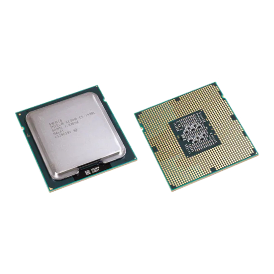
Package Mechanical & Storage Specifications Package Mechanical & Storage Specifications Package Mechanical Specifications The processor is packaged in a Flip-Chip Land Grid Array package that interfaces with the motherboard via the LGA1155 socket. The package consists of a processor mounted on a substrate land-carrier. An integrated heat spreader (IHS) is attached to the package substrate and core and serves as the mating surface for processor thermal solutions, such as a heatsink. -
Page 14: Package Mechanical Drawing
Package Mechanical & Storage Specifications 2.1.1 Package Mechanical Drawing Figure 2-2 shows the basic package layout and dimensions. The detailed package mechanical drawings are in Appendix D. The drawings include dimensions necessary to design a thermal solution for the processor. These dimensions include: 1. -
Page 15: Package Loading Specifications
Package Mechanical & Storage Specifications 2.1.3 Package Loading Specifications Table 2-1 provides dynamic and static load specifications for the processor package. These mechanical maximum load limits should not be exceeded during heatsink assembly, shipping conditions, or standard use condition. Also, any mechanical system or component testing should not exceed the maximum limits. -
Page 16: Processor Materials
This diagram is to aid in the identification of the processor. Figure 2-3. Processor Top-Side Markings Sample (QDF): GRP1LINE1: i{M}{C}YY GRP1LINE2: INTEL CONFIDENTIAL GRP1LINE3: QDF ES SPEED GRP1LINE4: COUNTRY OF ORIGIN GRP1LINE1 GRP1LINE5: {FPO} {e4}... -
Page 17: Processor Land Coordinates
Package Mechanical & Storage Specifications 2.1.9 Processor Land Coordinates Figure 2-4 shows the bottom view of the processor package. Figure 2-4. Processor Package Lands Coordinates 25 27 29 31 33 35 37 39 11 13 15 17 19 21 23 26 28 30 32 34 36 38 40 10 12 14 16 18 20 22 24 Thermal/Mechanical Specifications and Design Guidelines... -
Page 18: Processor Storage Specifications
ABSOLUTE STORAGE moisture barrier bags or desiccant. Intel branded board products are certified to meet the following temperature and humidity limits that are given as an example only (Non-Operating Temperature Limit: -40 °C to 70 °C, Humidity: 50% to 90%, non-condensing with a maximum wet bulb of 28 °C). -
Page 19: Lga1155 Socket
LGA1155 Socket LGA1155 Socket This chapter describes a surface mount, LGA (Land Grid Array) socket intended for the processors. The socket provides I/O, power and ground contacts. The socket contains 1155 contacts arrayed about a cavity in the center of the socket with lead-free solder balls for surface mounting on the motherboard. -
Page 20: Board Layout
LGA1155 Socket Figure 3-2. LGA1155 Socket Contact Numbering (Top View of Socket) U W AA AC AE AG AJ AL AN AR AU AW Y AB AD AF AH AK AM AP AT AV AY Board Layout The land pattern for the LGA1155 socket is 36 mils X 36 mils (X by Y) within each of the two L-shaped sections. -
Page 21: Lga1155 Socket Land Pattern (Top View Of Board)
LGA1155 Socket Figure 3-3. LGA1155 Socket Land Pattern (Top View of Board) W AA AC AE AG AJ AL AN AR AU AW AB AD AF AH AK AM AP AT AV AY 36mil (0.9144 mm) 122.6 mil (3.1144mm) W AA AC AE AG AJ AL AN AR AU AW AB AD AF AH AK AM AP AT AV AY Thermal/Mechanical Specifications and Design Guidelines... -
Page 22: Suggested Silkscreen Marking For Socket Identification
LGA1155 Socket 3.1.1 Suggested Silkscreen Marking for Socket Identification Intel is recommending that customers mark the socket name approximately where shown in Figure 3-4. Figure 3-4. Suggested Board Marking Attachment to Motherboard The socket is attached to the motherboard by 1155 solder balls. There are no additional external methods (that is, screw, extra solder, adhesive, and so on) to attach the socket. -
Page 23: Socket Components
LGA1155 Socket Socket Components The socket has two main components, the socket body and Pick and Place (PnP) cover, and is delivered as a single integral assembly. Refer to Appendix C for detailed drawings. 3.3.1 Socket Body Housing The housing material is thermoplastic or equivalent with UL 94 V-0 flame rating capable of withstanding 260 °C for 40 seconds which is compatible with typical reflow/rework profiles. -
Page 24: Package Installation / Removal
LGA1155 Socket Cover retention must be sufficient to support the socket weight during lifting, translation, and placement (board manufacturing), and during board and system shipping and handling. PnP Cover should only be removed with tools, to prevent the cover from falling into the contacts. The socket vendors have a common interface on the socket body where the PnP cover attaches to the socket body. -
Page 25: Socket Standoffs And Package Seating Plane
LGA1155 Socket Figure 3-7. Package Installation / Removal Features Package Orientation Pin 1 Notch Indicator (2 Places) Finger/Tool Access (2 Places) Alignment Post Pin 1 (2 Places) Chamfer 3.4.1 Socket Standoffs and Package Seating Plane Standoffs on the bottom of the socket base establish the minimum socket height after solder reflow and are specified in Appendix Similarly, a seating plane on the topside of the socket establishes the minimum... -
Page 26: Component Insertion Forces
LGA1155 Socket All markings must withstand 260 °C for 40 seconds (typical reflow/rework profile) without degrading, and must be visible after the socket is mounted on the motherboard. LGA1155 and the manufacturer's insignia are molded or laser marked on the side wall. Component Insertion Forces Any actuation must meet or exceed SEMI S8-95 Safety Guidelines for Ergonomics/ Human Factors Engineering of Semiconductor Manufacturing Equipment, example Table... -
Page 27: Independent Loading Mechanism (Ilm)
Intel performs detailed studies on integration of processor package, socket and ILM as a system. These studies directly impact the design of the ILM. The Intel reference ILM will be “build to print” from Intel controlled drawings. Intel recommends using the Intel Reference ILM. -
Page 28: Ilm Back Plate Design Overview
Caution: Intel does NOT recommend using the server back plate for high-volume desktop applications at this time as the server back plate test conditions cover a limited envelope. Back plates and screws are similar in appearance. To prevent mixing, different levels of differentiation between server and desktop back plate and screws have been implemented. -
Page 29: Shoulder Screw And Fasteners Design Overview
Independent Loading Mechanism (ILM) Figure 4-2. Back Plate Die Cut Die Cut Assembly Assembly Insulator Insulator Orientation Orientation Feature Feature Pierced & Extruded Pierced & Extruded Thread Features Thread Features 4.1.3 Shoulder Screw and Fasteners Design Overview The shoulder screw is fabricated from carbonized steel rod. The shoulder height and diameter are integral to the mechanical performance of the ILM. -
Page 30: Assembly Of Ilm To A Motherboard
Independent Loading Mechanism (ILM) Figure 4-3. Shoulder Screw 6-32 thread Shoulder Assembly of ILM to a Motherboard The ILM design allows a bottoms up assembly of the components to the board. See Figure 4-4 for step by step assembly sequence. 1. -
Page 31: Ilm Assembly
Independent Loading Mechanism (ILM) Figure 4-4. ILM Assembly Step 1 Step 1 Step 1 Step 2 Step 2 Step 2 Step 4 Step 4 Step 4 Step 3 Step 3 Step 3 As indicated in Figure 4-5, the shoulder screw, socket protrusion and ILM key features prevent 180 degree rotation of ILM cover assembly with respect to socket. -
Page 32: Ilm Interchangeability
Appendix A for vendor part numbers that were tested. Note: ILMs that are not compliant to the Intel controlled ILM drawings can not be assured to be interchangeable. Markings There are four markings on the ILM: •... -
Page 33: Ilm Cover
Independent Loading Mechanism (ILM) ILM Cover Intel has developed an ILM Cover that will snap onto the ILM for the LGA115x socket family. The ILM cover is intended to reduce the potential for socket contact damage from operator and customer fingers being close to the socket contacts to remove or install the pick and place cap. -
Page 34: Ilm Cover
Independent Loading Mechanism (ILM) Figure 4-6. ILM Cover Step 1: PnP Cover installed during ILM assembly Step 2: Remove PnP Cover Step 3: Close ILM As indicated in Figure 4-6, the pick and place cover should remain installed during ILM assembly to the motherboard. -
Page 35: Ilm Cover And Pnp Cover Interference
Independent Loading Mechanism (ILM) Figure 4-7. ILM Cover and PnP Cover Interference As indicated in Figure 4-7, the pick and place cover cannot remain in place and used in conjunction with the ILM Cover. The ILM Cover is designed to interfere and pop off if the pick and place cover is unintentionally left in place. - Page 36 Independent Loading Mechanism (ILM) Thermal/Mechanical Specifications and Design Guidelines...
-
Page 37: Lga1155 Socket And Ilm Electrical, Mechanical And Environmental Specifications
LGA1155 Socket and ILM Electrical, Mechanical and Environmental Specifications LGA1155 Socket and ILM Electrical, Mechanical and Environmental Specifications This chapter describes the electrical, mechanical and environmental specifications for the LGA1155 socket and the Independent Loading Mechanism. Component Mass Table 5-1. Socket Component Mass Component Mass... -
Page 38: Loading Specifications
This is the minimum and maximum static force that can be applied by the heatsink and it’s retention solution to maintain the heatsink to IHS interface. This does not imply the Intel reference TIM is validated to these limits. -
Page 39: Electrical Requirements
LGA1155 Socket and ILM Electrical, Mechanical and Environmental Specifications Electrical Requirements LGA1155 socket electrical requirements are measured from the socket-seating plane of the processor to the component side of the socket PCB to which it is attached. All specifications are maximum values (unless otherwise stated) for a single socket contact, but includes effects of adjacent contacts where indicated. -
Page 40: Environmental Requirements
Freeze stressing Perform stressing to requirements and perform validate accelerated additional data turns stressing assumptions and determine acceleration factors A detailed description of this methodology can be found at: ftp://download.intel.com/ technology/itj/q32000/pdf/reliability.pdf. § Thermal/Mechanical Specifications and Design Guidelines... -
Page 41: Thermal Specifications
ATX reference thermal solution design, please refer to Chapter Thermal Specifications To allow the optimal operation and long-term reliability of Intel processor-based systems, the processor must remain within the minimum and maximum case temperature (T ) specifications as defined by the applicable thermal profile. -
Page 42: Processor Thermal Specifications
Product Package Package Package Design (°C) TCASE Power (°C) 1,2,6 1,2,6 1,3,6 4,5,7 ® Intel Core™ i7- 2000 and i5-2000 Figure 6-1 desktop processor & Table 6-2 series (Quad Core 95W) ® Intel Core™ i7- 2000 and i5-2000 desktop processor... -
Page 43: Intel
® 6.1.1 Intel Core™ i7-2000 and i5-2000 Desktop Processor Series (Quad Core 95W) Thermal Profile Figure 6-1. Thermal Test Vehicle Thermal Profile for Intel ® Core™ i7-2000 and i5-2000 Desktop Processor Series (Quad Core 95W) Notes: Please refer to Table 6-2 for discrete points that constitute the thermal profile. -
Page 44: Thermal Test Vehicle Thermal Profile For Intel Core™ I7-2000 And I5-2000 Desktop Processor Series (Quad Core 65W) And Intel Core™ I3-2000 Desktop Processor Series (Dual Core 65W)
Desktop Processor Series (Dual Core 65W) Thermal Profile ® Figure 6-2. Thermal Test Vehicle Thermal Profile for Intel Core™ i7-2000 and i5-2000 Desktop Processor Series (Quad Core 65W) and Intel ® Core™ i3-2000 Desktop Processor Series (Dual Core 65W) Notes: Please refer to Table 6-3 for discrete points that constitute the thermal profile. - Page 45 Thermal Specifications ® Table 6-3. Thermal Test Vehicle Thermal Profile for Intel Core™ i7-2000 and i5-2000 ® Desktop Processor Series (Quad Core 65W) and Intel Core™ i3-2000 Desktop Processor Series (Dual Core 65W) Power (W) (C) Power (W) (C) CASE_MAX CASE_MAX 44.4...
-
Page 46: Thermal Profile
Thermal Specifications ® 6.1.3 Intel Core™ i5-2000 desktop processor series (Quad Core 45W) Thermal Profile Figure 6-3. Thermal Test Vehicle Thermal Profile for Intel ® Core™ i5-2000 Desktop Processor Series (Quad Core 45W) Notes: Please refer to Table 6-4 for discrete points that constitute the thermal profile. -
Page 47: Core™ I5-2000 And I3-2000 Desktop Processor Series (Dual Core 35W) Thermal Profile
® 6.1.4 Intel Core™ i5-2000 and i3-2000 Desktop Processor Series (Dual Core 35W) Thermal Profile Figure 6-4. Thermal Test Vehicle Thermal Profile for Intel ® Core™ i5-2000 and i3-2000 Desktop Processor Series (Dual Core 35W) Notes: Please refer to Table 6-5 for discrete points that constitute the thermal profile. -
Page 48: Processor Specification For Operation Where Digital Thermal Sensor Exceeds Tcontrol
(Quad Core 95W), Table 6-7 for the Intel Core™ i7-2000 and ® ® i5-2000 desktop processor series (Quad Core 65W) and Intel Pentium desktop ® processor 800 and 600 series (Dual Core 65W), Table 6-8 for the Intel Core™... - Page 49 Table 6-7. Thermal Solution Performance above T for the Intel ® Core™ i7-2000 CONTROL ® and i5-2000 Desktop Processor Series (Quad Core 65W) and Intel Core™ i3- 2000 Desktop Processor Series (Dual Core 65W) AMBIENT DTS = T...
-
Page 50: Desktop Processor Series (Quad Core 45W)
Thermal Specifications ® Table 6-8. Thermal Solution Performance above T for the Intel Core™ i5-2000 CONTROL Desktop Processor Series (Quad Core 45W) AMBIENT DTS = T DTS = -1 CONTROL 48.2 0.480 0.480 47.0 0.525 0.507 46.0 0.563 0.529... - Page 51 Thermal Specifications ® Table 6-9. Thermal Solution Performance above T for the Intel Core™ i5-2000 CONTROL and i3-2000 Desktop Processor Series (Dual Core 35W) AMBIENT DTS = T DTS = -1 CONTROL 48.2 0.480 0.480 47.0 0.538 0.514 46.0...
-
Page 52: Thermal Metrology
The following supplier can machine the groove and attach a thermocouple to the IHS. The supplier is listed below as a convenience to Intel’s general customers and the list may be subject to change without notice. THERM-X OF CALIFORNIA Inc, 3200 Investment Blvd, Hayward, Ca 94545. -
Page 53: Processor Thermal Features
Thermal Specifications Processor Thermal Features 6.2.1 Processor Temperature A new feature in the processors is a software readable field in the IA32_TEMPERATURE_TARGET register that contains the minimum temperature at which the TCC will be activated and PROCHOT# will be asserted. The TCC activation temperature is calibrated on a part-by-part basis and normal factory variation may result in the actual TCC activation temperature being higher than the value listed in the register. -
Page 54: Frequency/Vid Control
Thermal Specifications 6.2.2.1 Frequency/VID Control When the Digital Temperature Sensor (DTS) reaches a value of 0 (DTS temperatures reported via PECI may not equal zero when PROCHOT# is activated, see Section 6.2.2.5 for further details), the TCC will be activated and the PROCHOT# signal will be asserted. -
Page 55: Clock Modulation
Thermal Specifications Figure 6-6. Frequency and Voltage Ordering Temperature Temperature Frequency Frequency VIDf VIDf VIDf VIDf VIDf VIDf PROCHOT# PROCHOT# 6.2.2.2 Clock Modulation Clock modulation is a second method of thermal control available to the processor. Clock modulation is performed by rapidly turning the clocks off and on at a duty cycle that should reduce power dissipation by about 50% (typically a 30-50% duty cycle). -
Page 56: Critical Temperature Flag
Thermtrip temperature (see Section 6.2.3 Thermtrip Signal) within a short time. In order to prevent possible permanent silicon damage, Intel recommends removing power from the processor within ½ second of the Critical Temperature Flag being set 6.2.2.5... -
Page 57: Intel Turbo Boost Technology
TDP limit. Note: Intel Turbo Boost Technology processor frequencies are only active if the operating system is requesting the P0 state. ®... -
Page 58: Thermal Considerations
Thermal Considerations Intel Turbo Boost Technology allows processor cores and Processor Graphics cores to run faster than the baseline frequency. During a turbo event, the processor can exceed its TDP power for brief periods. Turbo is invoked opportunistically and automatically as long as the processor is conforming to its temperature, power delivery, and current specification limits. -
Page 59: Package Power Control
Circuitry (TCC) will protect the processor when properly enabled. Adaptive Thermal Monitor must be enabled for the processor to remain within specification. Illustration of Intel Turbo Boost Technology power control is shown in the following sections and figures. Multiple controls operate simultaneously allowing for customization for multiple system thermal and power limitations. -
Page 60: Power Plane Control
Thermal Specifications 6.4.3 Power Plane Control The processor core and graphics core power plane controls allow for customization to implement optimal turbo within voltage regulator thermal limitations. It is possible to use these power plane controls to protect the voltage regulator from overheating due to extended high currents. -
Page 61: Peci Interface
In this way, it is highly flexible even though underlying logic is simple. The interface design was optimized for interfacing to Intel processors in both single processor and multiple processor environments. The single wire interface provides low board routing overhead for the multiple load connections in the congested routing area near the processor and chipset components. - Page 62 PECI Interface Thermal/Mechanical Specifications and Design Guidelines...
-
Page 63: Sensor Based Thermal Specification Design Guidance
Sensor Based Thermal Specification Design Guidance Sensor Based Thermal Specification Design Guidance The sensor based thermal specification presents opportunities for the system designer to optimize the acoustics and simplify thermal validation. The sensor based specification utilizes the Digital Thermal Sensor information accessed via the PECI interface. -
Page 64: Comparison Of Case Temperature Versus Sensor Based Specification
Sensor Based Thermal Specification Design Guidance Figure 8-1. Comparison of Case Temperature versus Sensor Based Specification Ta = 45.1 °C Ta = 45.1 °C Tcontrol Tcontrol Ta = 30 °C Ta = 30 °C -ca = 0.292 -ca = 0.292 Power Power Current Specification (Case Temp) -
Page 65: Sensor Based Thermal Specification
The TTV is placed in the socket and powered to the recommended value to simulate the TDP condition. See Figure 8-2 for an example of the Intel ® Core™ i7-2000 and i5-2000 desktop processor series (Quad Core 95W) TTV thermal profile. -
Page 66: Specification When Dts Value Is Greater Than Tcontrol
Sensor Based Thermal Specification Design Guidance 8.2.2 Specification When DTS value is Greater than T CONTROL The product specification provides a table of values at DTS = T CONTROL DTS = -1 as a function of T (inlet to heatsink). Between these two defined AMBIENT points, a linear interpolation can be done for any DTS value reported by the processor. -
Page 67: Boundary Condition Definition
, which can have a lower cost. AMBIENT ® Figure 8-4 shows a number of satisfactory solutions for the Intel Core™ i7-2000 and i5-2000 desktop processor series (Quad Core 95W). Note: If the assumed T... -
Page 68: Thermal Design And Modelling
There are cost and acoustic trade-offs the customer can make. To aide in the design process Intel provides TTV thermal models. Please consult your Intel Field Sales Engineer for these tools. -
Page 69: Fan Speed Control (Fsc) Design Process
Sensor Based Thermal Specification Design Guidance Note: When selecting a thermal solution from a thermal vendor, the characterization data should be requested directly from them as a part of their thermal solution collateral. Figure 8-5. Thermal Solution Performance versus Fan Speed RPM vs. -
Page 70: Fan Speed Control Algorithm Without Tambient Data
AMBIENT derived in Section 8.3.1. This is consistent past FSC guidance from Intel, to accelerate the fan to full speed when the DTS value is greater than T . As will be shown below, the DTS thermal CONTROL specification at DTS = T... -
Page 71: Fan Speed Control Algorithm With Tambient Data
Sensor Based Thermal Specification Design Guidance Figure 8-6. Fan Response Without T Data AMBIENT 8.4.2 Fan Speed Control Algorithm with T Data AMBIENT In a system where the FSC algorithm has access to the T information and is AMBIENT capable of using the data the benefits of the DTS thermal specification become more striking. - Page 72 For simplicity the graph shows a linear acceleration of the fans from T - 10 to CONTROL as has been Intel’s guidance for simple fan speed control algorithms. CONTROL As the processor workload continues to increase, the DTS value will increase and the FSC algorithm will linearly increase the fan speed from the 1500 RPM at DTS = -20 to 2150 RPM at DTS value = -1.
-
Page 73: Dts 1.1 A New Fan Speed Control Algorithm Without Tambient Data
Sensor Based Thermal Specification Design Guidance 8.4.3 DTS 1.1 A New Fan Speed Control Algorithm without Data AMBIENT In most system designs incorporating processor ambient inlet data in fan speed control adds design and validation complexity with a possible BOM cost impact to the system. A new fan speed control methodology is introduced to improve system acoustics without needing the processor inlet ambient information. -
Page 74: Dts 1.1 Definition Points
Sensor Based Thermal Specification Design Guidance Figure 8-8. DTS 1.1 Definition Points Table 8-1. DTS 1.1 Thermal Solution Performance above T CONTROL DTS = -1 DTS = -1 DTS = -1 Processor TDP At System DTS = T At System At System CONTROL... -
Page 75: Fan Speed Control Implementation Details
Sensor Based Thermal Specification Design Guidance 8.4.4 Fan Speed Control Implementation Details Most fan controllers allow programming a few “temperature versus PWM” or “temperature v.s RPM” points for fan speed control and do a linear interpolation between the points. Using Table 8-1 determine the ... -
Page 76: System Validation
Sensor Based Thermal Specification Design Guidance Figure 8-9, the red line represents the DTS 1.1 fan speed control implementation. At 75W the fans will be ~ 1600 RPM keeping the Tj at ~ 89C. Blue line represent DTS 1.0 with ambient sensor. The fans with DTS 1.0 will be roughly at the same speed ~ 1650 RPM resulting in Tj at ~ 88 C. -
Page 77: Thermal Solution Characterization
Sensor Based Thermal Specification Design Guidance In the system under test and Power/Thermal Utility Software set to dissipate the TDP workload confirm the following item: • Verify if there is TCC activity by instrumenting the PROCHOT# signal from the processor. TCC activation in functional application testing is unlikely with a compliant thermal solution. -
Page 78: Thermal Solution Performance Above Tcontrol
Sensor Based Thermal Specification Design Guidance Table 8-3. Thermal Solution Performance above T (Sheet 2 of 2) CONTROL RPM for RPM for AMBIENT DTS = T DTS = T DTS = -1 DTS = -1 CONTROL CONTROL 28.0 0.600... -
Page 79: Atx Reference Thermal Solution
Intel. ® The design strategy is to use the design concepts from the prior Intel Radial Curved ® Bifurcated Fin Heatsink Reference Design (Intel RCBFH Reference Design) designed ®... -
Page 80: Atx Heatsink Reference Design Assembly
ATX Reference Thermal Solution Figure 9-1. ATX Heatsink Reference Design Assembly Thermal/Mechanical Specifications and Design Guidelines... -
Page 81: Geometric Envelope For The Intel Reference Atx Thermal Mechanical Design
ATX Reference Thermal Solution Geometric Envelope for the Intel Reference ATX Thermal Mechanical Design Figure 9-2 shows a 3-D representation of the board component keep out for the reference ATX thermal solution. A fully dimensioned drawing of the keep-out information is available at... -
Page 82: Reference Design Components
Solution Clip Mechanical Models and Mechanical Drawings to support power on with existing thermal solutions. Note: Intel reserves the right to make changes and modifications to the design as necessary to the reference design, in particular the clip. Thermal/Mechanical Specifications and Design Guidelines... -
Page 83: Core
ATX Reference Thermal Solution Figure 9-4. Clip for Existing Solutions to straddle LGA1155 Socket 9.3.3 Core The core is the same forged design used in previous reference designs. This allows the reuse of the fan attach and if desired the same extrusion from existing designs. The machined flange height will be determined in the preliminary design review to match the IHS height for the processors when installed in the LGA1155. -
Page 84: Mechanical Interface To The Reference Attach Mechanism
Figure B-9 for the component drawings. Note: For Intel RCFH6 and RCFH7 Reference Designs, the metal attach clip is not used by the solutions as shown in Figure 9-1. This metal attach clip design is only intended to adapt previous thermal solutions (such as the Intel RCBFH3 Reference Design) to comply with the mechanical and structural requirements for the LGA1155 socket. -
Page 85: Clip Core And Extrusion Assembly
ATX Reference Thermal Solution Figure 9-6. Clip Core and Extrusion Assembly Clip Core shoulder Core shoulder traps clip in place traps clip in place Figure 9-7. Critical Parameters for Interface to the Reference Clip Fin Array Fin Array Core Core See Detail A See Detail A Clip... -
Page 86: Heatsink Mass & Center Of Gravity
ATX Reference Thermal Solution Figure 9-8. Critical Core Dimensions Dia 38.68 +/- 0.30mm Dia 36.14 +/- 0.10 mm Gap required to avoid core surface blemish during clip assembly. Recommend 0.3 mm min. 1.00 +/- 0.10 mm Core 1.00 mm min R 0.40 mm max R 0.40 mm max 2.45 +/- 0.10 mm... -
Page 87: Heat Pipe Thermal Considerations
ATX Reference Thermal Solution Heat Pipe Thermal Considerations The following drawing shows the orientation and position of the 1155-land LGA Package TTV die, this is the same package layout as used in the 1156-land LGA Package TTV. The TTV die is sized and positioned similar to the production die. Figure 9-9. - Page 88 ATX Reference Thermal Solution Thermal/Mechanical Specifications and Design Guidelines...
-
Page 89: Thermal Solution Quality And Reliability Requirements
Based on the end user environment, the user should define the appropriate reliability test criteria and carefully evaluate the completed assembly prior to use in high volume. The Intel reference thermal solution will be evaluated to the boundary conditions in... -
Page 90: Recommended Test Sequence
• All enabling components, including socket and thermal solution parts. The pass criterion is that the system under test shall successfully complete the checking of BIOS, basic processor functions and memory, without any errors. Intel PC Diags is an example of software that can be utilized for this test. -
Page 91: Material And Recycling Requirements
Thermal Solution Quality and Reliability Requirements 10.3 Material and Recycling Requirements Material shall be resistant to fungal growth. Examples of non-resistant materials include cellulose materials, animal and vegetable based adhesives, grease, oils, and many hydrocarbons. Synthetic materials such as PVC formulations, certain polyurethane compositions (such as polyester and some polyethers), plastics which contain organic fillers of laminating materials, paints, and varnishes also are susceptible to fungal growth. - Page 92 Thermal Solution Quality and Reliability Requirements Thermal/Mechanical Specifications and Design Guidelines...
-
Page 93: Boxed Processor Specifications
11.1 Introduction The processor will also be offered as an Intel boxed processor. Intel boxed processors are intended for system integrators who build systems from baseboards and standard components. The boxed processor will be supplied with a cooling solution. This chapter documents baseboard and system requirements for the cooling solution that will be supplied with the boxed processor. -
Page 94: Mechanical Specifications
Boxed Processor Specifications Figure 11-1. Mechanical Representation of the Boxed Processor Note: The airflow of the fan heatsink is into the center and out of the sides of the fan heatsink. 11.2 Mechanical Specifications 11.2.1 Boxed Processor Cooling Solution Dimensions This section documents the mechanical specifications of the boxed processor. -
Page 95: Space Requirements For The Boxed Processor (Side View)
Boxed Processor Specifications Figure 11-2. Space Requirements for the Boxed Processor (side view) Figure 11-3. Space Requirements for the Boxed Processor (top view) Note: Diagram does not show the attached hardware for the clip design and is provided only as a mechanical representation. -
Page 96: Boxed Processor Fan Heatsink Weight
Boxed Processor Specifications Figure 11-4. Space Requirements for the Boxed Processor (overall view) 11.2.2 Boxed Processor Fan Heatsink Weight The boxed processor fan heatsink will not weigh more than 450 grams. 11.2.3 Boxed Processor Retention Mechanism and Heatsink Attach Clip Assembly The boxed processor thermal solution requires a heatsink attach clip assembly, to secure the processor and fan heatsink in the baseboard socket. -
Page 97: Boxed Processor Fan Heatsink Power Cable Connector Description
Boxed Processor Specifications Baseboards must provide a matched power header to support the boxed processor. Table 11-1 contains specifications for the input and output signals at the fan heatsink connector. The fan heatsink outputs a SENSE signal, which is an open- collector output that pulses at a rate of 2 pulses per fan revolution. -
Page 98: Thermal Specifications
Boxed Processor Specifications Figure 11-6. Baseboard Power Header Placement Relative to Processor Socket R110 [4.33] 11.4 Thermal Specifications This section describes the cooling requirements of the fan heatsink solution utilized by the boxed processor. 11.4.1 Boxed Processor Cooling Requirements The boxed processor may be directly cooled with a fan heatsink. However, meeting the processor's temperature specification is also a function of the thermal design of the entire system, and ultimately the responsibility of the system integrator. -
Page 99: Boxed Processor Fan Heatsink Airspace Keepout Requirements (Top View)
Boxed Processor Specifications Figure 11-7. Boxed Processor Fan Heatsink Airspace Keepout Requirements (top view) Figure 11-8. Boxed Processor Fan Heatsink Airspace Keepout Requirements (side view) Thermal/Mechanical Specifications and Design Guidelines... -
Page 100: Variable Speed Fan
Boxed Processor Specifications 11.4.2 Variable Speed Fan If the boxed processor fan heatsink 4-pin connector is connected to a 3-pin motherboard header it will operate as follows: The boxed processor fan will operate at different speeds over a short range of internal chassis temperatures. -
Page 101: Fan Heatsink Power And Signal Specifications
As processor power has increased, the required thermal solutions have generated increasingly more noise. Intel has added an option to the boxed processor that allows system integrators to have a quieter system in the most common usage. - Page 102 Boxed Processor Specifications Thermal/Mechanical Specifications and Design Guidelines...
-
Page 103: A Component Suppliers
The part numbers listed below identifies the reference components. End-users are responsible for the verification of the Intel enabled component offerings with the supplier. These vendors and devices are listed by Intel as a convenience to Intel's general customer base, but Intel does not make any representations or warranties whatsoever regarding quality, reliability, functionality, or compatibility of these devices. - Page 104 Component Suppliers Table A-4. Supplier Contact Information Supplier Contact Phone Email Kai Chang +86 755 3366 8888 kai_chang@avc.com.tw (Asia Vital x63588 Components Co., Ltd.) Delta William +1 510 668-5570 WBradshaw@delta-corp.com Bradshaw +86 136 8623 1080 Foxconn Julia Jiang +1 408 919 6178 juliaj@foxconn.com ITW Fastex Chak Chakir...
-
Page 105: B Mechanical Drawings
Mechanical Drawings Mechanical Drawings Table B-1 lists the mechanical drawings included in this appendix. Table B-1. Mechanical Drawing List Drawing Description Figure Number “Socket / Heatsink / ILM Keepout Zone Primary Side (Top)” Figure B-1 “Socket / Heatsink / ILM Keepout Zone Secondary Side (Bottom)” Figure B-2 “Socket / Processor / ILM Keepout Zone Primary Side (Top)”... - Page 106 Mechanical Drawings Figure B-1. Socket / Heatsink / ILM Keepout Zone Primary Side (Top) 46.89 45.50 37.31 2X 38.40 37.54 2X 36.89 33.80 26.70 28.46 25.79 25.81 21.25 23.81 18.90 20.90 10.00 0.00 5.40 10.50 10.00 20.13 2X 21.25 27.02 2X 25.25 29.69 35.03...
- Page 107 Mechanical Drawings Figure B-2. Socket / Heatsink / ILM Keepout Zone Secondary Side (Bottom) 37.54 25.81 13.67 0.00 13.67 35.21 35.21 40.71 Thermal/Mechanical Specifications and Design Guidelines...
- Page 108 Mechanical Drawings Figure B-3. Socket / Processor / ILM Keepout Zone Primary Side (Top) Thermal/Mechanical Specifications and Design Guidelines...
- Page 109 Mechanical Drawings Figure B-4. Socket / Processor / ILM Keepout Zone Secondary Side (Bottom) 25.70 0.00 25.70 18.00 0.00 18.00 Thermal/Mechanical Specifications and Design Guidelines...
- Page 110 Mechanical Drawings Figure B-5. Reference Design Heatsink Assembly Thermal/Mechanical Specifications and Design Guidelines...
- Page 111 Mechanical Drawings Figure B-6. Reference Fastener (Sheet 1 of 4) Thermal/Mechanical Specifications and Design Guidelines...
- Page 112 Mechanical Drawings Figure B-7. Reference Fastener (Sheet 2 of 4) Thermal/Mechanical Specifications and Design Guidelines...
- Page 113 Mechanical Drawings Figure B-8. Reference Fastener (Sheet 3 of 4) Thermal/Mechanical Specifications and Design Guidelines...
- Page 114 Mechanical Drawings Figure B-9. Reference Fastener (Sheet 4 of 4) Thermal/Mechanical Specifications and Design Guidelines...
- Page 115 Mechanical Drawings Figure B-10. Reference Clip (Sheet 1 of 2) Thermal/Mechanical Specifications and Design Guidelines...
- Page 116 Mechanical Drawings Figure B-11. Reference Clip (Sheet 2 of 2) Thermal/Mechanical Specifications and Design Guidelines...
- Page 117 Mechanical Drawings Figure B-12. Thermocouple Attach Drawing Thermal/Mechanical Specifications and Design Guidelines...
- Page 118 Mechanical Drawings Figure B-13. ILM Shoulder Screw Thermal/Mechanical Specifications and Design Guidelines...
- Page 119 Mechanical Drawings Figure B-14. ILM Standard 6-32 Thread Fastener § Thermal/Mechanical Specifications and Design Guidelines...
- Page 120 Mechanical Drawings Thermal/Mechanical Specifications and Design Guidelines...
-
Page 121: C Socket Mechanical Drawings
Socket Mechanical Drawings Socket Mechanical Drawings Table C-1 lists the mechanical drawings included in this appendix. Table C-1. Mechanical Drawing List Drawing Description Figure Number “Socket Mechanical Drawing (Sheet 1 of 4)” Figure C-1 “Socket Mechanical Drawing (Sheet 2 of 4)” Figure C-2 “Socket Mechanical Drawing (Sheet 3 of 4)”... - Page 122 Socket Mechanical Drawings Figure C-1. Socket Mechanical Drawing (Sheet 1 of 4) Thermal/Mechanical Specifications and Design Guidelines...
- Page 123 Socket Mechanical Drawings Figure C-2. Socket Mechanical Drawing (Sheet 2 of 4) Thermal/Mechanical Specifications and Design Guidelines...
- Page 124 Socket Mechanical Drawings Figure C-3. Socket Mechanical Drawing (Sheet 3 of 4) Thermal/Mechanical Specifications and Design Guidelines...
- Page 125 Socket Mechanical Drawings Figure C-4. Socket Mechanical Drawing (Sheet 4 of 4) § Thermal/Mechanical Specifications and Design Guidelines...
- Page 126 Socket Mechanical Drawings Thermal/Mechanical Specifications and Design Guidelines...
- Page 127 Package Mechanical Drawings Package Mechanical Drawings Table D-1 lists the mechanical drawings included in this appendix. Table D-1. Mechanical Drawing List Drawing Description Figure Number “Processor Package Drawing (Sheet 1 of 2)” Figure D-1 “Processor Package Drawing (Sheet 2of 2)” Figure D-2 Thermal/Mechanical Specifications and Design Guidelines...
- Page 128 Package Mechanical Drawings Figure D-1. Processor Package Drawing (Sheet 1 of 2) Thermal/Mechanical Specifications and Design Guidelines...
- Page 129 Package Mechanical Drawings Figure D-2. Processor Package Drawing (Sheet 2of 2) § Thermal/Mechanical Specifications and Design Guidelines...
- Page 130 Package Mechanical Drawings Thermal/Mechanical Specifications and Design Guidelines...
- Page 131 Design modifications for specific application and manufacturing are the responsibility of OEM and the listed vendors for customized system implementation and validation. These vendors and devices are listed by Intel as a convenience to Intel's general customer base, but Intel does not make any representations or warranties whatsoever regarding quality, reliability, functionality, or compatibility of these devices.
- Page 132 Heat Sink Back Plate Drawings Figure E-1. Heat Sink Back Plate Keep In Zone Thermal/Mechanical Specifications and Design Guidelines...
- Page 133 Heat Sink Back Plate Drawings Figure E-2. Heat Sink Back Plate Thermal/Mechanical Specifications and Design Guidelines...
- Page 134 Heat Sink Back Plate Drawings Figure E-3. Reference Design ILM Back Plate § Thermal/Mechanical Specifications and Design Guidelines...
Need help?
Do you have a question about the 2ND GENERATION INTEL CORE PROCESSOR FAMILY DESKTOP - THERMAL MECHANICAL SPECIFICATIONS AND DESIGN GUIDELINES 01-2011 and is the answer not in the manual?
Questions and answers