
Related Manuals for Intel SR1425BK1 - Entry Server Platform


Summary of Contents for Intel SR1425BK1 - Entry Server Platform
-
Page 1: Technical Product Specification
® Intel Server Chassis SC1400UP / ® Intel Server Platform SR1425BK1-E Technical Product Specification Intel order number C94051-001 Revision 1.0 October 2004 Enterprise Platforms and Services Marketing... -
Page 2: Revision History
Revision History Date Revision Modifications Number February 2004 Updated to reflect Alpha – first external release July 2004 Added CPU air duct, updated SATA and SCSI backplane info, added LCP info, added riser card info, October 2004 Updated P/S specification October 2004 Final Release Revision 1.0... - Page 3 Intel disclaims any express or implied warranty, relating to sale and/or use of Intel products including liability or warranties relating to fitness for a particular purpose, merchantability, or infringement of any patent, copyright or other intellectual property right.
-
Page 4: Table Of Contents
Table of Contents 1. Intel® Server Chassis SC1400UP Feature Summary ..........- 13 - Chassis Views ....................- 13 - Chassis Dimensions ..................- 13 - Intel® Server Chassis SC1400UP System Components........- 14 - Rear Panel Components ...................- 15 - Hard Drive and Peripheral Bays ................- 15 - Control Panel .....................- 16 -... - Page 5 Control Panel LED Indicators ................- 43 - 4.2.1 Power / Sleep LED ....................- 44 - 4.2.2 System Status LED....................- 44 - 4.2.3 Drive Activity LED ....................- 45 - 4.2.4 System Identification LED..................- 45 - Control Panel Connectors..................- 46 - Internal Control Panel Assembly Headers ............- 46 - 5.
- Page 6 6.18 Power Factor Correction..................- 57 - 6.19 Efficiency ......................- 57 - 6.20 Grounding ......................- 58 - 6.21 Remote Sense ....................- 58 - 6.22 Output Power / Currents ..................- 58 - 6.22.1 Standby Outputs ....................- 59 - 6.22.2 Fan-less Operation ....................- 59 - 6.23 Voltage Regulation ....................- 59 - 6.23.1...
- Page 7 7.19.9 Maximum Allowable Temperatures on Power Cords.........- 73 - 8. Supported Intel® Server Boards...................- 74 - Intel® Server Board SE7221BK1-E Feature Set ..........- 74 - 9. Regulatory, Environmentals, and Specifications ............- 76 - Product Regulatory Compliance ................- 76 - 9.1.1 Product Safety Compliance ................- 76 -...
- Page 8 9.2.6 BSMI (Taiwan) ....................- 78 - Replacing the Back up Battery ................- 78 - System Level Environmental Limits ..............- 79 - Serviceability......................- 80 - Appendix A: Intel® Server Chassis SC1400UP Integration and Usage Tips......I Glossary............................II Revision 1.0 viii...
- Page 9 Figure 10. Intel® Server Chassis SC1400UP System Fans 4, 5, 6, 7, 8 ........- 21 - Figure 11. Intel® Server Platform SE7221BK1-E System Fan headers 4, 5, 6, 7, 8 ....- 21 - Figure 12. Air Baffle ........................- 22 - Figure 13.
- Page 10 Figure 36. Output Voltage Timing ...................- 62 - Figure 37. Turn On/Off Timing (Power Supply Signals)............- 63 - Figure 38. PSON# Required Signal Characteristic..............- 65 - Figure 39. SE7221BK1-E Board Layout .................- 75 - Revision 1.0...
- Page 11 List of Tables Table 1. Chassis Dimensions ....................- 13 - Table 2. Individual Fan Assy Pinout (J6J1, J6J2, J6J3, J6J4)..........- 22 - Table 3. 4-pin floppy power connector Pinout (J3) ..............- 25 - Table 4. 34-pin floppy connector Pinout (J2) ................- 25 - Table 5.
- Page 12 Table 35. Capacitve Loading Conditions ................- 60 - Table 36. Ripple and Noise.....................- 61 - Table 37. Output Voltage Timing ....................- 61 - Table 38. Turn On/Off Timing ....................- 62 - Table 39. Over Current Protection (OCP) ................- 64 - Table 40.
-
Page 13: Intel® Server Chassis Sc1400Up Feature Summary
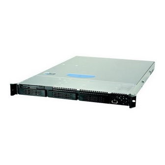
SE7221BK1-E server board comprise the Intel® Server Platform SR1425BK1-E. The SC1400UP is not offered as a standalone chassis solution from Intel and is only available as an integrated system as the SR1425BK1-E. Both the board and chassis have a feature set that is designed to support the high-density server market. -
Page 14: Intel® Server Chassis Sc1400Up System Components
Intel® Server Chassis SC1400UP / Intel® Server Platform SR1425BK1-E Intel® Server Chassis SC1400UP System Components Power supply Control Panel Chassis Intrusion Switch Hard Drive Bays Full length PCI Add in card slot Chassis Handle PCI Riser Card Assembly Placement Slim Line Drive Bay... -
Page 15: Rear Panel Components
SCSI drives or hot-swappable SATA or SCSI drives. SATA and SCSI hot-swap configurations require an orderable accessory kit which includes the necessary cables, drive trays and applicable backplane. Reference Intel Server Chassis SR1400 for detailed accessory information. The slim-line peripheral bay is capable of supporting any of the following slim-line devices: CDROM drive, DVD Drive, DVD/CDR Drive, or Floppy drive. -
Page 16: Control Panel
Intel® Server Chassis SC1400UP / Intel® Server Platform SR1425BK1-E Figure 4. Front Panel Feature Overview Slim-line drive bay (CDROM or DVD/CDR or Floppy) Control Panel Hard Drive Fault/Activity LED 1” Hard Drive Bays Chassis Handle Control Panel The Server Chassis SC1400UP control panel assembly is pre-assembled and modular in design. -
Page 17: Power Sub-System
Intel® Server Chassis SC1400UP / Intel® Server Platform SR1425BK1-E The control panel supports several push buttons and status LEDs, along with USB and video ports to centralize system control, monitoring, and accessibility to within a common compact design. The following diagram overviews the layout and functions of the control panel. -
Page 18: System Cooling
The optional front bezel is made of molded plastic and uses a snap-on design. When installed, its design allows for maximum airflow. Separate front bezels are available to support systems that use either a Standard Control Panel or Intel Local Control Panel. Figure 7. Optional Front Bezel Revision 1.0... -
Page 19: Figure 8. Front Bezel Options
Intel® Server Chassis SC1400UP / Intel® Server Platform SR1425BK1-E Light pipes in the front bezel supporting the Standard Control Panel allow the system status LEDs to be monitored with the bezel installed Figure 8. Front Bezel Options Revision 1.0 - 19 -... -
Page 20: Cooling Sub-System
Intel® Server Chassis SC1400UP / Intel® Server Platform SR1425BK1-E Cooling Sub-System The cooling sub-system on the SC1400UP is compromised of four 40x40x56mm dual rotor fans, one 40x40x28mm single rotor fan, two 40x40x28mm power supply fans, CPU/Memory air duct, and PS/Electronics Bay Isolation Air Baffle, to provide the necessary cooling and airflow to the system. -
Page 21: System Fans
Each dual rotor fan has an 8-pin wire harness which connects to the system fan headers 5,6,7 and 8 on the Intel Server Board SE7221BK1-E. These are shown, from left to right, in the following figure. Each fan harness provides power and tachometer lines allowing the fans to be monitored independently by server management software. -
Page 22: Power Supply Fans
Intel® Server Chassis SC1400UP / Intel® Server Platform SR1425BK1-E The following table provides the pin-outs for each dual rotor fan header. Table 2. Individual Fan Assy Pinout (J6J1, J6J2, J6J3, J6J4) Signal Name Description FAN_SPEED_CNTL2 Control the fan speed FAN_FAIL... -
Page 23: Hard Drive Bays
Intel® Server Chassis SC1400UP / Intel® Server Platform SR1425BK1-E designed to support either a single or dual processor configuration. For single processor configurations the pre-installed air damn must be left in place in order to maintain necessary air pressure and air flow through the processor heat sink. For dual processor configurations, the air damn must be snapped off of the CPU air duct. -
Page 24: Peripheral And Hard Drive Support
Floppy Drive Support with or without Backplane present Whether a SATA or SCSI backplane is used in the Intel Server Chassis SC1400UP or not, the floppy drive is mated with an interposer card which provides the power and IO interconnects between the drive, power supply and SE7221BK1-E baseboard. -
Page 25: Figure 16. Optional Floppy Drive Configuration
Intel® Server Chassis SC1400UP / Intel® Server Platform SR1425BK1-E Table 3. 4-pin floppy power connector Pinout (J3) Name P12V The power cable for the floppy drive is provided via a slimline Y cable which comes with the SC1400UP chassis. The third connector has 34 pins and is cabled to the legacy floppy connector on the baseboard. -
Page 26: Table 5. 50-Pin Cd-Rom Connector Pinout (J6)
Intel® Server Chassis SC1400UP / Intel® Server Platform SR1425BK1-E 3.1.1.2 CDROM or DVD-CDR Drive Use with or without Backplane present Regardless of whether a backplane is present or not, the slim-line CDROM or DVD-CDR drive is mated with an interposer card which provides the power and IO interconnects between the drive, power supply and baseboard. -
Page 27: Hard Disk Drive Bays
Intel® Server Chassis SC1400UP / Intel® Server Platform SR1425BK1-E The third connector has 40 pins and is cabled to the legacy IDE connector on the baseboard. This connector has the following pinout. Table 7. 40-pin CD-ROM connector Pinout (J1) Name... -
Page 28: Hot Swap Hard Disk Drive Trays
Intel® Server Chassis SC1400UP / Intel® Server Platform SR1425BK1-E 3.2.1 Hot Swap Hard Disk Drive Trays In a hot swap configuration, each hard drive must be mounted to a hot swap drive tray, making insertion and extraction of the drive from the chassis very simple. Each drive tray has its own dual purpose latching mechanism which is used to both insert/extract drives from the chassis and lock the tray in place. -
Page 29: Hot-Swap Scsi Backplane
Intel® Server Chassis SC1400UP / Intel® Server Platform SR1425BK1-E Figure 18. Drive Tray with Drive Blank Hot-Swap SCSI Backplane The SC1400UP SCSI hot-swap backplane (HSBP) supports the following feature set: ® QLogic GEM359 enclosure management controller o External non-volatile Flash ROM... -
Page 30: Scsi Backplane Functional Architecture
Intel® Server Chassis SC1400UP / Intel® Server Platform SR1425BK1-E SCSI Connector 100pin connector Power to SCSI add-in not used in Connector card SR1425BK1 Thumb Screw Floppy Drive Connector not used in SR1425BK1 IDE Connector Control Panel not used in Connector not... - Page 31 Intel® Server Chassis SC1400UP / Intel® Server Platform SR1425BK1-E 3.3.2.1 Enclosure Management Controller ® The SCSI backplane utilizes the features of the QLogic GEM359 for enclosure management which monitors various aspects of a storage enclosure. The chip provides in-band SAF-TE and SES management through the SCSI interface.
-
Page 32: Figure 21. Intel® Server Chassis Sc1400Up 1U Scsi Hsbp I2C Bus Connection Diagram
Intel® Server Chassis SC1400UP / Intel® Server Platform SR1425BK1-E Figure 21. Intel® Server Chassis SC1400UP 1U SCSI HSBP I2C Bus Connection Diagram 3.3.2.1.3 Temperature Sensor ® SC1400UP 1U SCSI HSBP provides a National Semiconductor LM75 or equivalent temperature sensor with over-temperature detector. The host can query the LM75 at any time to read the temperature. -
Page 33: Scsi Backplane Connector Definitions
Intel® Server Chassis SC1400UP / Intel® Server Platform SR1425BK1-E 3.3.3 SCSI Backplane Connector Definitions As a multi-functional board, several different connectors can be found on the SCSI backplane. This section defines the purpose and pin-out associated with each connector. 3.3.3.1... -
Page 34: Figure 23. 80-Pin Sca2 Scsi Interface
Intel® Server Chassis SC1400UP / Intel® Server Platform SR1425BK1-E Name Name BP_SCSI_DP0P BP_SCSI_DP0N BP_SCSI_DIFSNS TERMI_PWR TERMI_PWR TERMI_PWR TERMI_PWR Unused Unused BP_SCSI_ATNP BP_SCSI_ATNN BP_SCSI_BSYP BP_SCSI_BSYN BP_SCSI_ACKP BP_SCSI_ACKN BP_SCSI_RSTP BP_SCSI_RSTN BP_SCSI_MSGP BP_SCSI_MSGN BP_SCSI_SELP BP_SCSI_SELN BP_SCSI_CDP BP_SCSI_CDN BP_SCSI_REQP BP_SCSI_REQN BP_SCSI_IOP BP_SCSI_ION BP_SCSI_D8P BP_SCSI_D8N... -
Page 35: Table 10. 80-Pin Sca2 Scsi Interface Pinout (J9, J2, J10)
Intel® Server Chassis SC1400UP / Intel® Server Platform SR1425BK1-E Table 10. 80-pin SCA2 SCSI Interface Pinout (J9, J2, J10) Signal Name Signal Name P12V P12V P12V SCSI_MATED P12V NC_3V_CHG NC_3V_1 BP_SCSI_DIFSNS NC_3V_2 BP_SCSI_D11P BP_SCSI_D11N BP_SCSI_D10P BP_SCSI_D10N BP_SCSI_D9P BP_SCSI_D9N BP_SCSI_D8P BP_SCSI_D8N... -
Page 36: Hot-Swap Sata Backplane
Intel® Server Chassis SC1400UP / Intel® Server Platform SR1425BK1-E Hot-Swap SATA Backplane The SC1400UP 1U SATA Hot-Swap Back Plane (HSBP) supports the following feature set: ® QLogic GEM424 enclosure management controller o External non-volatile SEEPROMs o Three I C interfaces... -
Page 37: Sata Backplane Layout
Intel® Server Chassis SC1400UP / Intel® Server Platform SR1425BK1-E 3.4.1 SATA Backplane Layout The SATA backplane is located on the backside of the hot-swap drive bays on the inside of the chassis. Stand-offs on the chassis and a single thumb screw make for easy tool-less installation. -
Page 38: Figure 26. Sata Backplane Functional Block Diagram
Intel® Server Chassis SC1400UP / Intel® Server Platform SR1425BK1-E Figure 26. SATA Backplane Functional Block Diagram 3.4.2.1 Enclosure Management Controller ® The SC1400UP SATA backplane utilizes the features and functionality of the QLogic GEM424 enclosure management controller, which is capable of monitoring various aspects of a storage enclosure. -
Page 39: Figure 27. Intel® Server Chassis Sc1400Up 1U Sata Hsbp I2C Bus Connection Diagram
C port 0. The figure below provides a block diagram of I C bus connection implemented on the SC1400UP 1U SATA HSBP. Figure 27. Intel® Server Chassis SC1400UP 1U SATA HSBP I2C Bus Connection Diagram 3.4.2.1.3 Temp Sensor ® SC1400UP 1U SATA HSBP provides National LM75 or equivalent temperature sensor with over-temperature detector. -
Page 40: Sata Backplane Connector Definitions
SATA Connectors (Backplane to Baseboard) The SATA backplane has three 7-pin SATA connectors (Drive0, Drive1 and Drive2). These connectors correspond to the SATA connectors on the Intel Server Board SE7221BK1-E (SATA1, SATA2 and SATA3). The backplane connectors relay SATA signals from the baseboard to the ATA drives. -
Page 41: Table 13. 7-Pin Sata Connector Pinout (J2, J3, J4, J5, J6)
With a slim-line floppy drive installed into either the slim-line drive bay or the optionally installed floppy drive kit located in one of the hard drive bays, the floppy cable from the drive is routed to the legacy floppy connector on the baseboard floppy connector on the Intel Server Board SE7221BK1-E. -
Page 42: Standard Control Panel
Intel® Server Chassis SC1400UP / Intel® Server Platform SR1425BK1-E Standard Control Panel The standard control panel supports several push buttons and status LEDs, along with USB and video ports to centralize system control, monitoring, and accessibility to within a common compact design. -
Page 43: Control Panel Led Indicators
Intel® Server Chassis SC1400UP / Intel® Server Platform SR1425BK1-E Table 15. Contol Button and Intrusion Switch Functions Reference Feature Function Power / Sleep Toggles the system power on/off. This button also functions as a Sleep Button if Button enabled by an ACPI-compliant operating system. -
Page 44: Power / Sleep Led
4.2.2 System Status LED Note: Some of the following status conditions may or may not be reported if the system is not configured with an Intel Management Module. Refer to the baseboard technical product specification for details. Revision 1.0 - 44 -... -
Page 45: Drive Activity Led
Intel® Server Chassis SC1400UP / Intel® Server Platform SR1425BK1-E 4.2.2.1 Critical Conditions A critical condition is any critical or non-recoverable threshold crossing associated with the following events: • Temperature, voltage, or fan critical threshold crossing. • Power subsystem failure. The BMC asserts this failure whenever it detects a power control fault (e.g., the BMC detects that the system power is remaining ON even though... -
Page 46: Control Panel Connectors
Intel® Server Chassis SC1400UP / Intel® Server Platform SR1425BK1-E Control Panel Connectors The control panel has one external I/O connectors: • One USB port The following tables provide the pin-outs for each connectors. Table 18. External USB Connectors (J1B1) Pin #... -
Page 47: Table 19. 50-Pin Control Panel Connector (J6B1)
Intel® Server Chassis SC1400UP / Intel® Server Platform SR1425BK1-E Table 19. 50-pin Control Panel Connector (J6B1) Description Pin # Pin # Description PWR_LCD_5VSB PWR_LCD_5VSB HDD_LED_ACT_R_L Unused RST_P6_PWRGOOD FP_SYS_FLT_LED1_R_L P5V_STBY FP_SYS_FLT_LED2_R_L FP_PWR_LED_R_L P5V_STBY IPMB_5VSB_SDA P3V3 IPMB_5VSB_SCL FP_PWR_BTN_L FP_ID_LED_R_L HDD_FAULT_LED_R_L NIC2_LINK_LED_R_L FP_RST_BTN_L... -
Page 48: Pci Riser Cards And Assembly
Intel® Server Chassis SC1400UP / Intel® Server Platform SR1425BK1-E PCI Riser Cards and Assembly The Intel® Server Board SE7221BK1-E provides 1 PCI riser slot (Intel® Adaptive Slot), supporting full height/full length add-in card risers. The riser slot is capable of supporting risers that follow either the PCI-X or PCI-Express specifications. -
Page 49: Figure 32. 1U Full Height Pci-X Riser Card Mechanical Drawing
Intel® Server Chassis SC1400UP / Intel® Server Platform SR1425BK1-E Figure 32. 1U Full Height PCI-X Riser Card Mechanical Drawing Figure 33. 1U Full Height PCI-Express Riser Card Mechanical Drawing Revision 1.0 - 49 -... -
Page 50: Power Sub-System
Intel® Server Chassis SC1400UP / Intel® Server Platform SR1425BK1-E Power Sub-system The power sub-system of the Server Chassis SC1400UP consists of a single non-redundant 300W power supply with 7 outputs; 3.3V, 5V, 12V1, 12V2, 12V3, -12V and 5VSB. The form factor fits into a 1U system and provides a wire harness output to the system. -
Page 51: Airflow Requirements
Intel® Server Chassis SC1400UP / Intel® Server Platform SR1425BK1-E Notes: 1. All dimensions are in mm. 2. The tolerance of the 40mm height dimension (marked with letter C) pertains to the metal case only. Airflow Requirements The power supply incorporates two 40mm fans for self cooling and system cooling. The fans provide no less than 10 CFM airflow through the power supply when installed in the system. -
Page 52: Temperature
Intel® Server Chassis SC1400UP / Intel® Server Platform SR1425BK1-E Temperature The power supply operates within all specified limits over the T temperature range. (See Sec.7 for detailed environmental requirements). The average air temperature difference (∆T from the inlet to the outlet of the power supply should not exceed 20C. All airflow passes through the power supply and not over the exterior surfaces of the power supply. -
Page 53: P2 Processor Power Connector
Intel® Server Chassis SC1400UP / Intel® Server Platform SR1425BK1-E SIGNAL 18 AWG COLOR SIGNAL 18 AWG COLOR +5 VDC* Black Black COM VS(3.3V) Black 22AWG Black +5 VDC Black Black COM VS Black 22AWG Reserved PWR OK Gray N.C. 5VSB... -
Page 54: Ac Inlet Connector
Intel® Server Chassis SC1400UP / Intel® Server Platform SR1425BK1-E AC Inlet Connector The AC input connector shall be an IEC 320 C-14 power inlet. This inlet is rated for 15A / 250VAC. Marking and Identification The power supply module marking supports the following requirements, safety agency requirements, government requirements (if required, e.g. -
Page 55: Susceptibility
The power supply meets the following electrical immunity requirements when connected to a cage with an external EMI filter which meets the criteria defined in the SSI document EPS Power Supply Specification. For further information on Intel standards please request a copy of the Intel Environmental Standards Handbook Table 30. -
Page 56: Ac Line Fast Transient (Eft) Specification
11:1995 test standard and performance criteria C defined in Annex B of CISPR 24. In addition the power supply shall meet the following Intel Requirements: A continuous input voltage below the nominal input range shall not damage the power supply or cause overstress to any power supply component. -
Page 57: Ac Line Inrush
The power supply shall meet all safety agency requirements for dielectric strength. Additionally, power supply vendor must provide Intel with written confirmation of dielectric withstand test which includes: voltage level, duration of test and identification detailing how each power supply is marked to indicate dielectric withstand test had been completed successfully. -
Page 58: Grounding
Intel® Server Chassis SC1400UP / Intel® Server Platform SR1425BK1-E 6.20 Grounding The ground of the pins of the power supply output connector provides the power return path. The output connector ground pins are connected to safety ground (power supply enclosure). -
Page 59: Standby Outputs
Intel® Server Chassis SC1400UP / Intel® Server Platform SR1425BK1-E Note: Maximum continuous total DC output power should not exceed 300 Watts. Peak total DC output power should not exceed 350 Watts peak. Peak power and peak current loading shall be supported for a minimum of 12 seconds. -
Page 60: Capacitive Loading
Intel® Server Chassis SC1400UP / Intel® Server Platform SR1425BK1-E Table 34. Transient Load Requirements Output ∆ Step Load Size Load Slew Rate Test capacitive Load (See note 2) +3.3V 5.0A 250 µF 0.25 A/µsec 400 µF 6.0A 0.25 A/µsec 9.0A 500 µF... -
Page 61: Ripple / Noise
Intel® Server Chassis SC1400UP / Intel® Server Platform SR1425BK1-E 6.27 Ripple / Noise The maximum allowed ripple/noise output of the power supply is defined in Table 36. Ripple and Noise below. This is measured over a bandwidth of 0Hz to 20MHz at the power supply output connectors. -
Page 62: Table 38. Turn On/Off Timing
Intel® Server Chassis SC1400UP / Intel® Server Platform SR1425BK1-E Vout Vout vout_off vout rise vout_on Figure 36. Output Voltage Timing Table 38. Turn On/Off Timing Item Description UNITS Delay from AC being applied to 5VSB being msec sb_on_delay 1500 within regulation. -
Page 63: Residual Voltage Immunity In Standby Mode
Intel® Server Chassis SC1400UP / Intel® Server Platform SR1425BK1-E AC Input vout_holdup Vout pwok_low AC_on_delay pwok_off sb_on_delay sb_on_delay pwok_on pwok_off pwok_on PWOK pson_pwok pwok_holdup 5VSB sb_vout 5VSB holdup pson_on_delay PSON AC turn on/off cycle PSON turn on/off cycle Figure 37. Turn On/Off Timing (Power Supply Signals) 6.31 Residual Voltage Immunity in Standby mode... -
Page 64: Over Voltage Protection (Ovp)
Intel® Server Chassis SC1400UP / Intel® Server Platform SR1425BK1-E Table 39. Over Current Protection (OCP) VOLTAGE OVER CURRENT LIMIT (Iout limit) +3.3V 16A min; 25A max 19A min; 30A max +12V 21A min; 30A max 5VSB 2.5 min; 5.0A max 6.34 Over Voltage Protection (OVP) -
Page 65: Pson
Intel® Server Chassis SC1400UP / Intel® Server Platform SR1425BK1-E 6.37 PSON Input Signal The PSON signal is required to remotely turn on/off the power supply. PSON is an active low signal that turns on the +3.3V, +5V, +12V, and -12V power rails. When this signal is not pulled low by the system, or left open, the outputs (except the +5VSB) turn off. -
Page 66: Environmental Requirements
Intel® Server Chassis SC1400UP / Intel® Server Platform SR1425BK1-E supply operation is no longer guaranteed, PWOK will be de-asserted to a LOW state. See Figure 37. Turn On/Off Timing for a representation of the timing characteristics of PWOK. The start of the PWOK delay time shall inhibited as long as any power supply output is in current limit. -
Page 67: Random Vibration
Intel® Server Chassis SC1400UP / Intel® Server Platform SR1425BK1-E 6.44 Random Vibration Non-operating Sine sweep: 5Hz to 500Hz @ 0.5gRMS at 0.5 octave/minute; dwell 15 min at each of 3 resonant points; Random profile: 5Hz @ 0.01g²/Hz to 20Hz @ 0.02g²/Hz (slope up); 20Hz to 500Hz @ 0.02g²/Hz (flat);... -
Page 68: Electromagnetic Compatibility
100VAC 50Hz, 120 VAC 60 Hz, and 230 VAC 50 Hz power. The power supply shall comply with EN55024. The power supply when installed in the system must meet all the immunity requirements when integrated into the end Intel system. Input Line Current Harmonic Content (PFC) -
Page 69: Voltage Fluctuations And Flicker
Power supplies returned to the vendor for repair, are returned for full credit. Power supplies returned from vendor repair will be accepted by Intel only after the vendor has performed an additional burn-in of 4 hours min. at 45°C ± 5°C at maximum load and has re- tested the power supply following the burn-in. -
Page 70: Modifications / Change Control
Qualification Inspection/Test Procedure. Intel reserves the right to negate Type One (form, fit, safety, function, or reliability) changes within 30 days. All Type One changes must be submitted to Intel for review and must be approved in writing. Modification to certification records shall be provided to Intel upon completion. -
Page 71: Emc Compliance Information
Intel® Server Chassis SC1400UP / Intel® Server Platform SR1425BK1-E 7.15 EMC Compliance Information For Power Supply Vendor Certification Process refer to Section 5 Australia / New Zealand AS/NZS 3548 (Based on CISPR 22) – Class B Canada ICES-003 - Class A... -
Page 72: Other Safety Requirement Notations
Green PC eco-label Sweden TCO eco-label Materials used in the power supply shall comply with Intel’s Environmental Product content Specification located at http://supplier.intel.com/ehs/environmental.htm If the power supply is an external power supply rated less than 75 watts, the power supply shall comply with the European Commission’s “Code of Conduct for External Power Supplies.”... -
Page 73: Date Coded Serial Numbers
Intel® Server Chassis SC1400UP / Intel® Server Platform SR1425BK1-E required, it shall be placed in such a manner that when the power supply is extracted from the system, the label shall be visible before the operator has a chance to touch the hot surface of the power supply. -
Page 74: Supported Intel® Server Boards
Intel® Server Chassis SC1400UP / Intel® Server Platform SR1425BK1-E Supported Intel® Server Boards The Intel® Server Chassis SC1400UP is mechanically and functionally designed to support the Intel® Server Board SE7221BK1-E. Intel® Server Board SE7221BK1-E Feature Set • Pentium® 4 LGA-775 processor socket, supporting 800MHz Front Side Bus (FSB) •... -
Page 75: Figure 39. Se7221Bk1-E Board Layout
Intel® Server Chassis SC1400UP / Intel® Server Platform SR1425BK1-E Socket Q P O TP01326 Figure 39. SE7221BK1-E Board Layout Table 44: Baseboard Layout Reference A Chassis Intrusion Header DIMM Sockets DIMM_1B, DIMM_2B 34-pin Front Panel Connector B PCI 32/33 Slot... -
Page 76: Regulatory, Environmentals, And Specifications
The SC1400UP has been tested and verified to comply with the following electromagnetic compatibility (EMC) regulations when installed a compatible Intel host system. For information on compatible host system(s) refer to Intel’s Server Builder website or contact your local Intel representative. -
Page 77: Electromagnetic Compatibility Notices
Intel® Server Chassis SC1400UP / Intel® Server Platform SR1425BK1-E Electromagnetic Compatibility Notices 9.2.1 This device complies with Part 15 of the FCC Rules. Operation is subject to the following two conditions: (1) this device may not cause harmful interference, and (2) this device must accept any interference received, including interference that may cause undesired operation. -
Page 78: Ices-003 (Canada)
Intel® Server Chassis SC1400UP / Intel® Server Platform SR1425BK1-E Intel Corporation 5200 N.E. Elam Young Parkway Hillsboro, OR 97124-6497 Phone: 1 (800)-INTEL4U or 1 (800) 628-8686 9.2.3 ICES-003 (Canada) Cet appareil numérique respecte les limites bruits radioélectriques applicables aux appareils numériques de Classe A prescrites dans la norme sur le matériel brouilleur: “Appareils... -
Page 79: System Level Environmental Limits
Intel® Server Chassis SC1400UP / Intel® Server Platform SR1425BK1-E settings stored in CMOS RAM in the RTC (for example, the date and time) may be wrong. Contact your customer service representative or dealer for a list of approved devices. WARNING Danger of explosion if battery is incorrectly replaced. -
Page 80: Serviceability
Non-palletized free fall in height 24 inches (≧40 lbs to > 80 lbs) Vibration, unpackaged 5 Hz to 500 Hz, 2.20 g RMS random Shock, operating Half sine, 2 g peak, 11 mSec +/-15kV except I/O port +/-8KV per Intel Environmental test specification System Cooling 1826 BTU/hour Requirement in BTU/Hr Serviceability The system is designed to be serviced by qualified technical personnel only. -
Page 81: Appendix A: Intel® Server Chassis Sc1400Up Integration And Usage Tips
Intel® Server Chassis SC1400UP / Intel® Server Platform SR1425BK1-E Appendix A: Intel® Server Chassis SC1400UP Integration and Usage Tips This section provides a list of useful information that is unique to the server chassis SC1400UP and should be kept in mind while integrating and configuring your server board SE7221BK1-E. -
Page 82: Glossary
Intel® Server Chassis SC1400UP / Intel® Server Platform SR1425BK1-E Glossary Glossary Word / Acronym Definition Australian Communication Authority ANSI American National Standards Institute Baseboard Management Controller CMOS Complementary Metal Oxide Silicon DC-to-DC Emergency Management Port Front Panel Fault Resilient Boot...
Need help?
Do you have a question about the SR1425BK1 - Entry Server Platform and is the answer not in the manual?
Questions and answers