Sign In
Upload
Manuals
Brands
Intel Manuals
Chassis
SR1425BK1 - Entry Server Platform
Intel SR1425BK1 - Entry Server Platform Manuals
Manuals and User Guides for Intel SR1425BK1 - Entry Server Platform. We have
1
Intel SR1425BK1 - Entry Server Platform manual available for free PDF download: Technical Specifications
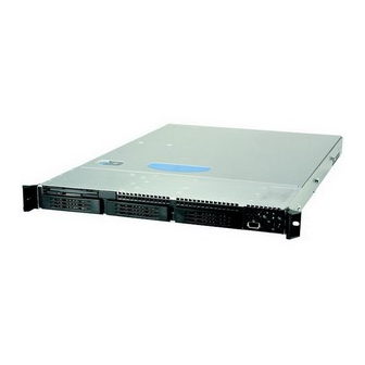
Intel SR1425BK1 - Entry Server Platform Technical Specifications (82 pages)
Server Chassis and Server Chassis
Brand:
Intel
| Category:
Chassis
| Size: 2 MB
Table of Contents
Technical Product Specification
1
Revision History
2
Table of Contents
4
1 Intel® Server Chassis SC1400UP Feature Summary
13
Chassis Views
13
Chassis Dimensions
13
Figure 1. Front and Rear Chassis Views
13
Table 1. Chassis Dimensions
13
Intel® Server Chassis SC1400UP System Components
14
Figure 2. Major Chassis Components
14
Rear Panel Components
15
Hard Drive and Peripheral Bays
15
Figure 3. Back Panel Feature Overview
15
Control Panel
16
Figure 4. Front Panel Feature Overview
16
Figure 5. Control Panel Module
16
Power Sub-System
17
Figure 6. Standard Control Panel Overview
17
System Cooling
18
Chassis Security
18
Rack and Cabinet Mounting Options
18
Front Bezels
18
Figure 7. Optional Front Bezel
18
Figure 8. Front Bezel Options
19
2 Cooling Sub-System
20
Figure 9. Intel® Server Chassis SC1400UP Cooling Subsystem
20
System Fans
21
Power Supply Fans
22
Cpu/Memory Air Duct and Side Air Baffle
22
Figure 12. Air Baffle
22
Table 2. Individual Fan Assy Pinout (J6J1, J6J2, J6J3, J6J4)
22
Hard Drive Bays
23
Figure 13. Cpu/Memory Air Duct
23
3 Peripheral and Hard Drive Support
24
Slimline Drive Bay
24
Floppy Drive Support with or Without Backplane Present
24
Figure 14. Intel® Server Chassis SC1400UP Peripheral Bay Configuration Options
24
Figure 15. View of Slim-Line Drive Bay
24
Figure 16. Optional Floppy Drive Configuration
25
Table 3. 4-Pin Floppy Power Connector Pinout (J3)
25
Table 4. 34-Pin Floppy Connector Pinout (J2)
25
Table 5. 50-Pin CD-ROM Connector Pinout (J6)
26
Table 6. 4-Pin CD-ROM Power Connector Pinout (J5)
26
Hard Disk Drive Bays
27
Table 7. 40-Pin CD-ROM Connector Pinout (J1)
27
Drive Blanks
28
Figure 17. Hard Drive Tray Assembly
28
Fixed Drive Trays
28
Hot Swap Hard Disk Drive Trays
28
Hot-Swap SCSI Backplane
29
Hot-Swap SCSI Backplane Board Layout
29
Figure 18. Drive Tray with Drive Blank
29
SCSI Backplane Functional Architecture
30
Figure 19. Hot-Swap SCSI Backplane Layout
30
Figure 20. Hot-Swap SCSI Backplane Functional Diagram
30
Figure 21. Intel® Server Chassis SC1400UP 1U SCSI HSBP I2C Bus Connection Diagram
32
SCSI Backplane Connector Definitions
33
Figure 22. 68-Pin SCSI Cable Connector
33
Table 8. SCSI Backplane Power Connector Pinout (J1)
33
Table 9. Ultrawide (SE) and Ultra2 (LVD) Ultra320 SCSI Connector Pinout (J8)
33
Figure 23. 80-Pin SCA2 SCSI Interface
34
Table 10. 80-Pin SCA2 SCSI Interface Pinout (J9, J2, J10)
35
Hot-Swap SATA Backplane
36
SATA Backplane Layout
37
SATA Backplane Functional Architecture
37
Figure 24. SATA Backplane Layout
37
Figure 26. SATA Backplane Functional Block Diagram
38
Figure 27. Intel® Server Chassis SC1400UP 1U SATA HSBP I2C Bus Connection Diagram
39
SATA Backplane Connector Definitions
40
Table 11. LED Function
40
Table 12. SATA Backplane Power Connector Pinout
40
Table 13. 7-Pin SATA Connector Pinout (J2, J3, J4, J5, J6)
41
Table 14. 22-Pin SATA Connector Pinout
41
4 Standard Control Panel
42
Control Panel Buttons
42
Figure 28. Standard Control Panel Assembly Module
42
Figure 29. Control Panel Buttons
42
Control Panel LED Indicators
43
Table 15. Contol Button and Intrusion Switch Functions
43
Table 16. Control Panel LED Functions
43
Power / Sleep LED
44
System Status LED
44
Table 17. SSI Power LED Operation
44
Drive Activity LED
45
System Identification LED
45
Control Panel Connectors
46
Internal Control Panel Assembly Headers
46
Table 18. External USB Connectors (J1B1)
46
Table 19. 50-Pin Control Panel Connector (J6B1)
47
Table 20. Internal USB Header (J2B1)
47
5 PCI Riser Cards and Assembly
48
Riser Card Options
48
Figure 31. PCI Riser Bracket and Optional PCI-X and PCI-Express Risers
48
Figure 32. 1U Full Height PCI-X Riser Card Mechanical Drawing
49
Figure 33. 1U Full Height PCI-Express Riser Card Mechanical Drawing
49
6 Power Sub-System
50
Mechanical Specifications
50
Figure 34. Power Supply Enclosure Drawing
50
Airflow Requirements
51
Acoustics
51
Figure 35. Airflow Characteristics
51
Table 21. Acoustic Requirements
51
Temperature
52
Output Connectors
52
P1 Main Power Connector
52
Table 22. Environmental Requirements
52
Table 23. Cable Lengths
52
Table 24. P1 Main Power Connector
52
P2 Processor Power Connector
53
P3-P5 Peripheral Connectors
53
Table 25. P2 Processor Power Connector
53
Table 26. Peripheral Power Connectors
53
AC Inlet Connector
54
Marking and Identification
54
AC Input Voltage
54
AC Line Transient Specification
54
Table 27. AC Input Rating
54
Table 28. AC Line Sag Transient Performance
54
Susceptibility
55
Electrostatic Discharge Susceptibility
55
Fast Transient/Burst
55
Radiated Immunity
55
Surge Immunity
55
Table 29. AC Line Surge Transient Performance
55
Table 30. Performance Criteria
55
AC Line Fast Transient (EFT) Specification
56
AC Line Dropout / Holdup
56
AC Line 5VSB Holdup
56
Power Recovery
56
Voltage Brown out
56
Voltage Interruptions
56
AC Line Inrush
57
AC Line Isolation Requirements
57
AC Line Leakage Current
57
AC Line Fuse
57
Power Factor Correction
57
Efficiency
57
Grounding
58
Remote Sense
58
Output Power / Currents
58
Table 31. Load Ratings
58
Table 32. Load Range 2
58
Fan-Less Operation
59
Standby Outputs
59
Voltage Regulation
59
Dynamic Loading
59
Table 33. Voltage Regulation Limits
59
Capacitive Loading
60
Closed Loop Stability
60
Common Mode Noise
60
Table 34. Transient Load Requirements
60
Table 35. Capacitve Loading Conditions
60
Ripple / Noise
61
Soft Starting
61
Zero Load Stability Requirements
61
Timing Requirements
61
Figure 36. Output Voltage Timing
61
Table 36. Ripple and Noise
61
Table 37. Output Voltage Timing
61
Table 38. Turn On/Off Timing
62
Residual Voltage Immunity in Standby Mode
63
Protection Circuits
63
Current Limit (OCP)
63
Figure 37. Turn On/Off Timing (Power Supply Signals)
63
Over Voltage Protection (OVP)
64
Over Temperature Protection (OTP)
64
Control and Indicator Functions
64
Table 39. over Current Protection (OCP)
64
Table 40. over Voltage Protection (OVP) Limits
64
Pson
65
PWOK (Power OK) Output Signal
65
Figure 38. PSON# Required Signal Characteristic
65
Environmental Requirements
66
Temperature
66
Humidity
66
Altitude
66
Mechanical Shock
66
Table 42. PWOK Signal Characteristics
66
Random Vibration
67
Thermal Shock (Shipping)
67
Ecological Requirements
67
Catastrophic Failure
67
7 Electromagnetic Compatibility
68
Emi
68
Input Line Current Harmonic Content (PFC)
68
Magnetic Leakage Fields
68
Table 43. Harmonic Limits, Class a Equipment
68
Voltage Fluctuations and Flicker
69
Reliability / Warranty / Service
69
Component De-Rating
69
Component Life Requirement
69
Mean Time between Failures (MTBF)
69
Warranty Period
69
Serviceability
69
Power Supply Returned for Repair
69
Modifications / Change Control
70
Power Supply Compliance Overview
70
Power Supplies Compliance Information
70
EMC Compliance Information
71
Immunity Compliance Information
71
Harmonics & Voltage Flicker Compliance Information
71
Environmental / Ecology Compliance Information
71
Other Safety Requirement Notations
72
Certification Conditions
72
Isolation between Primary - Secondary
72
Creepage & Clearance Requirements
72
Leakage Current Maximums
72
Max Surface Temperatures
72
Date Coded Serial Numbers
73
Power Input Electrical Ratings
73
Maximum Allowable Temperatures on Inlet Receptacles
73
Maximum Allowable Temperatures on Power Cords
73
8 Supported Intel® Server Boards
74
Intel® Server Board SE7221BK1-E Feature Set
74
Figure 39. SE7221BK1-E Board Layout
75
Table 44: Baseboard Layout Reference
75
9 Regulatory, Environmentals, and Specifications
76
Product Regulatory Compliance
76
Product Safety Compliance
76
Product EMC Compliance
76
Product Regulatory Compliance Markings
76
Electromagnetic Compatibility Notices
77
Usa
77
FCC Verification Statement
77
ICES-003 (Canada)
78
Europe (CE Declaration of Conformity)
78
Japan EMC Compatibility
78
BSMI (Taiwan)
78
Replacing the Back up Battery
78
System Level Environmental Limits
79
Table 45. System Office Environment Summary
79
Serviceability
80
Table 46. Mean Time to Repair Estimate
80
Appendix A: Intel® Server Chassis SC1400UP Integration and Usage Tips
81
Glossary
82
Advertisement
Advertisement
Related Products
Intel SR1425BK1-E
Intel SR2300 - FRONT BEZEL BLK
Intel SR1560SF - Server System - 0 MB RAM
Intel SR1500 - AXXMINIDIMM DDR-2 RAID Controller Cache Memory
Intel SR1550
Intel SR1600
Intel SR1625
Intel SR2500
Intel SR2600
Intel SR2625
Intel Categories
Motherboard
Computer Hardware
Server
Server Board
Desktop
More Intel Manuals
Login
Sign In
OR
Sign in with Facebook
Sign in with Google
Upload manual
Upload from disk
Upload from URL