Table of Contents
Advertisement
Quick Links
Connect Tech Inc.
42 Arrow Road
Guelph, Ontario
N1K 1S6
www.connecttech.com
CTIM-00439 Revision 0.00 2015/05/25
ES France - Mobilité & Systèmes Embarqués
127 rue de Buzenval BP 26 - 92380 Garches
SMARC/SL
Users Guide
Tel:
Toll:
Fax:
Email:
Tél. 01 47 95 99 80
Fax. 01 47 01 16 22
519-836-1291
800-426-8979 (North America only)
519-836-4878
sales@connecttech.com
support@connecttech.com
e-mail : mse@es-france.com
Site Web : www.es-france.com
Advertisement
Table of Contents

Related Manuals for Connect Tech SMARC/SL


Summary of Contents for Connect Tech SMARC/SL
- Page 1 SMARC/SL Users Guide Connect Tech Inc. Tel: 519-836-1291 42 Arrow Road Toll: 800-426-8979 (North America only) Guelph, Ontario Fax: 519-836-4878 N1K 1S6 Email: sales@connecttech.com www.connecttech.com support@connecttech.com CTIM-00439 Revision 0.00 2015/05/25 Tél. 01 47 95 99 80 e-mail : mse@es-france.com ES France - Mobilité & Systèmes Embarqués Fax.
-
Page 2: Table Of Contents
System ................................... 18 Camera Connector ..............................18 USB 2.0 ................................. 19 Jumper Description ............................. 20 J1A Jumper – SMARC/SL Carrier Reset ......................20 J1B Jumper – Ext SATA/mSATA Selection ......................20 Typical Installation ............................21 On-Board Indicator LED’s .......................... 21 Current Consumption Details ........................ - Page 3 CBG185 - MIPI-CSI 2-Lane Camera 20-Pin Hirose to Flying Lead Cable ............32 Document: CTIM-00439 Page 3 of 32 Date: 2015/05/25 Revision: 0.00 Connect Tech Inc. 800-426-8979 | 519-836-1291 Tél. 01 47 95 99 80 e-mail : mse@es-france.com ES France - Mobilité & Systèmes Embarqués Fax. 01 47 01 16 22 Site Web : www.es-france.com...
-
Page 4: Preface
The information contained within this user’s guide, including but not limited to any product specification, is subject to change without notice. Connect Tech assumes no liability for any damages incurred directly or indirectly from any technical or typographical errors or omissions contained herein or for discrepancies between the product and the user’s guide. -
Page 5: Limited Product Warranty
Connect Tech Inc. provides a two year Warranty for the SMARC/SL Carrier. Should this product, in Connect Tech Inc.'s opinion, fail to be in good working order during the warranty period, Connect Tech Inc. will, at its option, repair or replace this product at no charge, provided that the product has not been subjected to abuse, misuse, accident, disaster or non-Connect Tech Inc. -
Page 6: Esd Warning
ESD Warning Electronic components and circuits are sensitive to ElectroStatic Discharge (ESD). When handling any circuit board assemblies including Connect Tech Carrier Assemblies, it is recommended that ESD safety precautions be observed. ESD safe best practices include, but are not limited to: ... -
Page 7: Introduction
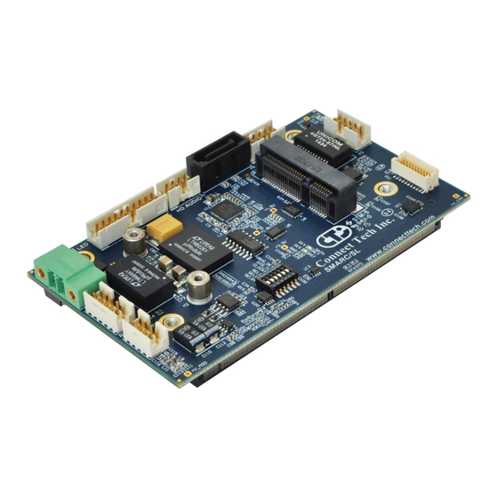
Introduction Connect Tech’s SMARC/SL Carrier is a super small SMARC Carrier Board ideal for your low power application. The SMARC/SL Carrier has the ability to use both +3.3V and +1.8V SMARC Modules, a single Mini- PCIe/mSATA with External SATA switching, Gigabit Ethernet, HDMI Video, and MIPI CSI Camera interface. -
Page 8: Product Overview
Block Diagram Document: CTIM-00439 Page 8 of 32 Date: 2015/05/25 Revision: 0.00 Connect Tech Inc. 800-426-8979 | 519-836-1291 Tél. 01 47 95 99 80 e-mail : mse@es-france.com ES France - Mobilité & Systèmes Embarqués Fax. 01 47 01 16 22 Site Web : www.es-france.com... -
Page 9: Connector Locations
Connector Locations Document: CTIM-00439 Page 9 of 32 Date: 2015/05/25 Revision: 0.00 Connect Tech Inc. 800-426-8979 | 519-836-1291 Tél. 01 47 95 99 80 e-mail : mse@es-france.com ES France - Mobilité & Systèmes Embarqués Fax. 01 47 01 16 22 Site Web : www.es-france.com... -
Page 10: Connector Summary
USB Client Power control to disable +5V at output Document: CTIM-00439 Page 10 of 32 Date: 2015/05/25 Revision: 0.00 Connect Tech Inc. 800-426-8979 | 519-836-1291 Tél. 01 47 95 99 80 e-mail : mse@es-france.com ES France - Mobilité & Systèmes Embarqués Fax. 01 47 01 16 22 Site Web : www.es-france.com... -
Page 11: Detailed Feature Description
In SMARC Systems, the processor, chipset, and power control are all implemented on the SMARC Module. This connects to the SMARC Carrier via a MXM 3.0 Style Connector. SMARC The processor and chipset are implemented on the SMARC Module, which connects to the SMARC/SL Carrier Board via a MXM 3.0 fine pitch connector. Function... -
Page 12: Hd Audio
Linux Driver: Included in kernels 2.6.30 and up. Document: CTIM-00439 Page 12 of 32 Date: 2015/05/25 Revision: 0.00 Connect Tech Inc. 800-426-8979 | 519-836-1291 Tél. 01 47 95 99 80 e-mail : mse@es-france.com ES France - Mobilité & Systèmes Embarqués Fax. 01 47 01 16 22 Site Web : www.es-france.com... -
Page 13: Hdmi Connector
MX3+ Document: CTIM-00439 Page 13 of 32 Date: 2015/05/25 Revision: 0.00 Connect Tech Inc. 800-426-8979 | 519-836-1291 Tél. 01 47 95 99 80 e-mail : mse@es-france.com ES France - Mobilité & Systèmes Embarqués Fax. 01 47 01 16 22 Site Web : www.es-france.com... -
Page 14: Microsd Card
SD_D3 SD_CMD SD_VDD SD_CLK SD_D0 SD_D1 SD_CD# External SATA The SMARC/SL Carrier provides an External SATA connector that is SATA/mSATA switched. Please see Mini-PCIe/mSATA Slot description for additional details. Function External SATA Location Type Molex Vertical Serial ATA Plug 0471554001... -
Page 15: Mini-Pcie/Msata Slots
Half and Full Length Mini-PCIe/mSATA Module Installation The SMARC/SL Carrier is designed with mounting holes to allow for the population a full length module. To install a half-length module you must use a Mini-PCIe Half to Full Size Extension Bracket. - Page 16 +3.3V Document: CTIM-00439 Page 16 of 32 Date: 2015/05/25 Revision: 0.00 Connect Tech Inc. 800-426-8979 | 519-836-1291 Tél. 01 47 95 99 80 e-mail : mse@es-france.com ES France - Mobilité & Systèmes Embarqués Fax. 01 47 01 16 22 Site Web : www.es-france.com...
-
Page 17: Power Input
SMARC/SL Users Guide www.connecttech.com Power Input The SMARC/SL Carrier accepts a single power input to power all on-board devices. A single +6V to +36V input is required for operation. Function Power Location Type Phoenix Contact Pluggable Terminal Block 1843790 1847055... -
Page 18: System
Note [1]: +V_CAM is a +3.3V Rail, However this can be modified upon request Document: CTIM-00439 Page 18 of 32 Date: 2015/05/25 Revision: 0.00 Connect Tech Inc. 800-426-8979 | 519-836-1291 Tél. 01 47 95 99 80 e-mail : mse@es-france.com ES France - Mobilité & Systèmes Embarqués Fax. 01 47 01 16 22 Site Web : www.es-france.com... -
Page 19: Usb 2.0
Port B - GND Document: CTIM-00439 Page 19 of 32 Date: 2015/05/25 Revision: 0.00 Connect Tech Inc. 800-426-8979 | 519-836-1291 Tél. 01 47 95 99 80 e-mail : mse@es-france.com ES France - Mobilité & Systèmes Embarqués Fax. 01 47 01 16 22 Site Web : www.es-france.com... -
Page 20: Jumper Description
SMARC/SL Users Guide www.connecttech.com Jumper Description The SMARC/SL Carrier has a single jumper blocks for Carrier Reset and SATA Control. J1A Jumper – SMARC/SL Carrier Reset Function Carrier Reset Location Pinout Position Description Place SMARC/SL Carrier into Reset Normal Operation J1B Jumper –... -
Page 21: Typical Installation
Connect the Power Cable to the Power Supply Switch ON the Power Supply. DO NOT power up your system by plugging in live power. On-Board Indicator LED’s The SMARC/SL Carrier has 7 on-board indicator LEDs. Description GBE ACT# GBE LINK# +V_MOD +3.3V... -
Page 22: Current Consumption Details
Theoretical Absolute Maximum Total Draw of All Functionality on the SMARC/SL Carrier Board Below are measurements taken with the SMARC/SL Carrier running in various configurations. Some values will change depending on what SMARC Module is installed. Please refer to the module manufacturer’s manual for full details on the current consumption of the particular module you are using. -
Page 23: Mechanical Details
SMARC/SL Users Guide www.connecttech.com Mechanical Details A complete 3D STEP Model file of SMARC/SL Carrier can be downloaded here: http://www.connecttech.com/ftp/3d_models/SRG001_3D_MODEL.zip 2D Mechanical Dimensioned Drawing - PCB and Mounting Hole Dimension are in mm. Top View Bottom View Document: CTIM-00439 Page 23 of 32 Date: 2015/05/25 Revision: 0.00... -
Page 24: Cables
SMARC/SL Users Guide www.connecttech.com Cables The following table summarizes the SMARC/SL Carrier cables available. Cable Kits CKG034 Drawing No. Part No. Description Cable Kit CBG079 SATA HDD Signal Cable CTIC-00429 CBG104 Dual USB 2.0 to 8-Pin MiniTek Cable CTIC-00433 CBG117... -
Page 25: Cbg079 - Sata Hdd Signal Cable
CBG079 - SATA HDD Signal Cable Document: CTIM-00439 Page 25 of 32 Date: 2015/05/25 Revision: 0.00 Connect Tech Inc. 800-426-8979 | 519-836-1291 Tél. 01 47 95 99 80 e-mail : mse@es-france.com ES France - Mobilité & Systèmes Embarqués Fax. 01 47 01 16 22 Site Web : www.es-france.com... -
Page 26: Cbg104 - Dual Usb 2.0 To 8-Pin Minitek Cable
CBG104 - Dual USB 2.0 to 8-Pin MiniTek Cable Document: CTIM-00439 Page 26 of 32 Date: 2015/05/25 Revision: 0.00 Connect Tech Inc. 800-426-8979 | 519-836-1291 Tél. 01 47 95 99 80 e-mail : mse@es-france.com ES France - Mobilité & Systèmes Embarqués Fax. 01 47 01 16 22 Site Web : www.es-france.com... -
Page 27: Cbg117 - Rj-45 To 10-Pin Minitek Cable
CBG117 - RJ-45 to 10-Pin MiniTek Cable Document: CTIM-00439 Page 27 of 32 Date: 2015/05/25 Revision: 0.00 Connect Tech Inc. 800-426-8979 | 519-836-1291 Tél. 01 47 95 99 80 e-mail : mse@es-france.com ES France - Mobilité & Systèmes Embarqués Fax. 01 47 01 16 22 Site Web : www.es-france.com... -
Page 28: Cbg118 - Dual Audio To 8-Pin Minitek Cable
CBG118 - Dual Audio to 8-Pin MiniTek Cable Document: CTIM-00439 Page 28 of 32 Date: 2015/05/25 Revision: 0.00 Connect Tech Inc. 800-426-8979 | 519-836-1291 Tél. 01 47 95 99 80 e-mail : mse@es-france.com ES France - Mobilité & Systèmes Embarqués Fax. 01 47 01 16 22 Site Web : www.es-france.com... -
Page 29: Cbg127 - Db9 To 10-Pin Minitek Cable
CBG127 - DB9 to 10-Pin MiniTek Cable Document: CTIM-00439 Page 29 of 32 Date: 2015/05/25 Revision: 0.00 Connect Tech Inc. 800-426-8979 | 519-836-1291 Tél. 01 47 95 99 80 e-mail : mse@es-france.com ES France - Mobilité & Systèmes Embarqués Fax. 01 47 01 16 22 Site Web : www.es-france.com... -
Page 30: Cbg134 - 10-Pin Minitek System Cable
CBG134 - 10-Pin MiniTek System Cable Document: CTIM-00439 Page 30 of 32 Date: 2015/05/25 Revision: 0.00 Connect Tech Inc. 800-426-8979 | 519-836-1291 Tél. 01 47 95 99 80 e-mail : mse@es-france.com ES France - Mobilité & Systèmes Embarqués Fax. 01 47 01 16 22 Site Web : www.es-france.com... -
Page 31: Cbg145 - Hdmi Female To 20-Pin Minitek Cable
CBG145 - HDMI Female to 20-Pin MiniTek Cable Document: CTIM-00439 Page 31 of 32 Date: 2015/05/25 Revision: 0.00 Connect Tech Inc. 800-426-8979 | 519-836-1291 Tél. 01 47 95 99 80 e-mail : mse@es-france.com ES France - Mobilité & Systèmes Embarqués Fax. 01 47 01 16 22 Site Web : www.es-france.com... -
Page 32: Cbg185 - Mipi-Csi 2-Lane Camera 20-Pin Hirose To Flying Lead Cable
CBG185 - MIPI-CSI 2-Lane Camera 20-Pin Hirose to Flying Lead Cable Document: CTIM-00439 Page 32 of 32 Date: 2015/05/25 Revision: 0.00 Connect Tech Inc. 800-426-8979 | 519-836-1291 Tél. 01 47 95 99 80 e-mail : mse@es-france.com ES France - Mobilité & Systèmes Embarqués Fax. 01 47 01 16 22 Site Web : www.es-france.com...
Need help?
Do you have a question about the SMARC/SL and is the answer not in the manual?
Questions and answers