Table of Contents
Advertisement
Quick Links
Advertisement
Table of Contents

Related Manuals for Connect Tech SMARC 2.0


Summary of Contents for Connect Tech SMARC 2.0
- Page 1 SMARC 2.0 Carrier CTIM-00154 Revision 0.04 2021-06-18...
-
Page 2: Table Of Contents
Figure 1 Top view ............................8 Figure 2 Bottom view ............................8 Jumper/Switch Summary & Locations ......................9 Detailed Feature Description ........................10 SMARC 2.0 Connector ........................... 10 Fan Connector ............................... 11 Video Output ..............................11 MIPI CSI Video Input ............................12 MIPI CSI x4/x2 Connector ........................ -
Page 3: Preface
The information contained within this user’s guide, including but not limited to any product specification, is subject to change without notice. Connect Tech assumes no liability for any damages incurred directly or indirectly from any technical or typographical errors or omissions contained herein or for discrepancies between the product and the user’s guide. -
Page 4: Limited Product Warranty
Connect Tech Inc. provides a two-year Warranty for this product. Should this product, in Connect Tech Inc.'s opinion, fail to be in good working order during the warranty period, Connect Tech Inc. will, at its option, repair or replace this product at no charge, provided that the product has not been subjected to abuse, misuse, accident, disaster or non-Connect Tech Inc. -
Page 5: Esd Warning
ESD Warning Electronic components and circuits are sensitive to ElectroStatic Discharge (ESD). When handling any circuit board assemblies including Connect Tech COM Express carrier assemblies, it is recommended that ESD safety precautions be observed. ESD safe best practices include, but are not limited to: •... -
Page 6: Introduction
INTRODUCTION Connect Tech’s SMARC 2.0 carrier is an extremely small SMARC carrier board ideal for low power IoT applications as users can take advantage of the integrated on-board wireless capabilities found on the SMARC 2.0 modules. The carrier has USB 3.0, USB 2.0, 2x MIPI CSI-2 camera interfaces, HDMI outputs, microSD, and expansion via two mini PCIe Full size slots. -
Page 7: Product Overview
SMARC 2.0 Carrier Users Guide www.connecttech.com PRODUCT OVERVIEW Block Diagram Document: CTIM-00154 Page 7 of 22 Date: 2021-06-18 Revision: 0.04... -
Page 8: Connector Summary & Locations
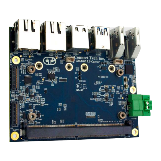
SMARC 2.0 Carrier Users Guide www.connecttech.com Connector Summary & Locations Figure 1 Top view Figure 2 Bottom view Document: CTIM-00154 Page 8 of 22 Date: 2021-06-18 Revision: 0.04... -
Page 9: Jumper/Switch Summary & Locations
SMARC 2.0 Carrier Users Guide www.connecttech.com Designator Description HDMI0 HDMI1 GPIO Header I2C Header Mini PCIe Slot 0 Mini PCIe/mSATA Slot 1 +5V Power Input External RTC Header System Control Header RS-232 Serial Header USB2.0 double stack, ports 0/1 USB3.0 double stack, ports 2/3... -
Page 10: Detailed Feature Description
SMARC 2.0 Carrier Users Guide www.connecttech.com DETAILED FEATURE DESCRIPTION SMARC 2.0 Connector The processor and chipset are implemented on the SMARC 2.0 Module, which connects to the SMARC 2.0 Carrier via an MXM 3.0 fine pitch connector. Function Description Location Type JAE Electronics MXM 3.0 Connector... -
Page 11: Fan Connector
SMARC 2.0 Carrier Users Guide www.connecttech.com Fan Connector The SMARC 2.0 Carrier implements a 4 pin header for the connection of a +5V fan. No PWM control is available from this header. Function Description Location Type Molex Vertical PicoBlade Part Number PN: 530470410... -
Page 12: Mipi Csi Video Input
MIPI CSI Video Input The SMARC 2.0 Carrier implements two MIPI CSI camera inputs through 28 pin Hirose ZIF connectors compatible with Basler BCON cables. The pinout of this connector is compatible with Basler MIPI BCON cameras. For additional information on camera support please contact sales@connecttech.com. -
Page 13: Mipi Csi X2 Connector
SMARC 2.0 Carrier Users Guide www.connecttech.com MIPI CSI x2 Connector Function Description Location Part Number Hirose FH41-28S-0.5SH(05) Pinout Pin Description Pin Description GPIO (GPIO11) I2C_SCL I2C_SDA GPIO (GPIO9) GPIO (GPIO4) CLK+ CLK- DATA1+ DATA1- DATA0+ DATA0- RST# (CAM0_RST#) Switched by CAM1_PWR#... -
Page 14: Network
Number Pinout Refer to IEEE 802.3 The SMARC 2.0 Carrier implements a Dual USB3.0 connector and a Dual USB2.0 connector. All ports are direct from the SMARC 2.0 module. All connectors are industry standard USB3.0/USB2.0 Type A right angle. Function... -
Page 15: Mini-Pcie/Msata Slots
Mini-PCIe/mSATA Slots The SMARC 2.0 Carrier implements two expansion slots. One is Mini PCIe only and the other is a dual function Mini PCIe/mSATA socket. The dual purpose functional Mini-PCIe/mSATA socket located at P8 can accept either a Mini PCIe module or an mSATA module. - Page 16 SMARC 2.0 Carrier Users Guide www.connecttech.com 24 +3.3V +3.3V 25 PCIe RX+ SATA TX- 26 GND 27 GND 28 +1.5V +1.5V 29 GND 30 SMB_CLK SMB_CLK 31 PCIe TX- SATA RX- 32 SMB_DATA SMB_DATA 33 PCIe TX+ SATA RX+ 34 GND...
-
Page 17: Carrier Control Dip Switch
SMARC 2.0 Carrier Users Guide www.connecttech.com Carrier Control DIP Switch Function Description Location S1 Modes Pin Description Function 1 Mini-PCIe/mSATA select mSATA Mini-PCIe 2 CARRIER_PWR_ON Always-ON Module Controlled 3 BOOT_SEL0# OPEN 4 BOOT_SEL1# OPEN 5 BOOT_SEL2# OPEN 6 USB_OTG_ID OPEN Functionality and support depend on the module vendor. -
Page 18: I2C Connector
2 GND 3 DATA S49 - I2C_GP_DAT 3.3V logic level RS-232 Serial Connector The SMARC 2.0 Carrier implements a 9 pin header that connects to the UART0 interface via an RS232 transceiver from the SMARC 2.0 module. Function Description Location... -
Page 19: Microsd Card Slot
Molex microSD Push-Push Type Part Number 5025700893 Pinout Refer to SD Card Standard GPIO Connector The SMARC 2.0 Carrier implements a 10 pin header that connects to a MaxLinear XRA1200 I C GPIO expander at address 0x40. Function Description Location... -
Page 20: Power Input
SMARC 2.0 Carrier Users Guide www.connecttech.com Power Input The SMARC 2.0 Carrier accepts a single power input to power all onboard devices. A single +5V DC (± 5%) input is required for operation. Function Description Location Type Tyco Pluggable Terminal Block... -
Page 21: System Control Connector
SMARC 2.0 Carrier Users Guide www.connecttech.com System Control Connector The SMARC 2.0 Carrier implements a 10 pin header that connects to several system control signals from the SMARC module. Function Description Location Type Molex Right-Angle PicoBlade Part Number 0532611071 Mating... -
Page 22: Typical Installation
3. Install the necessary cables for the application. For the relevant cables, see the Cables and Accessories section of this manual. 4. Connect the power cable to the SMARC 2.0 Carrier then to the power supply. 5. Switch on the power supply. DO NOT power up your SMARC system by plugging in live power.
Need help?
Do you have a question about the SMARC 2.0 and is the answer not in the manual?
Questions and answers