Table of Contents
Advertisement
Quick Links
Advertisement
Table of Contents

Subscribe to Our Youtube Channel
Related Manuals for AXIOMTEK eBOX671B Series


Summary of Contents for AXIOMTEK eBOX671B Series
- Page 1 Series Embedded System User’s Manual...
-
Page 2: Disclaimers
Axiomtek does not make any commitment to update any information in this manual. Axiomtek reserves the right to change or revise this document and/or product at any time without notice. No part of this document may be reproduced, stored in a retrieval system, or transmitted in any forms or by any means, electronic, mechanical, photocopying, recording, among others, without prior written permissions of Axiomtek Co., Ltd. -
Page 3: Safety Precautions
Safety Precautions Before getting started, please read the following important safety precautions. The eBOX671B does not come with an operating system which must be loaded first before installation of any software into the computer. Be sure to ground yourself to prevent static charge when installing any internal components. -
Page 4: Classifications
Classifications Degree of production against electric shock: not classified Degree of protection against ingress of water: IP40 Equipment not suitable for use in the presence of a flammable anesthetic mixture with air, oxygen or nitrous oxide. Mode of operation: Continuous... -
Page 5: General Cleaning Tips
General Cleaning Tips Please keep the following precautions in mind while understanding the details fully before and during any cleaning of the computer and any components within. A piece of dry cloth is ideal to clean the device. Be cautious of any tiny removable components when using a vacuum cleaner to absorb dirt on the floor. -
Page 6: Scrap Computer Recycling
Scrap Computer Recycling Please inform the nearest Axiomtek distributor as soon as possible for suitable solutions in case computers require maintenance or repair; or for recycling in case computers are out of order. Trademarks Acknowledgments Axiomtek is a trademark of Axiomtek Co., Ltd. -
Page 7: Table Of Contents
Table of Contents Disclaimers ......................ii Safety Precautions ....................iii Classifications ....................... iv General Cleaning Tips ................... v Scrap Computer Recycling ................... vi SECTION 1 INTRODUCTION................. 1 General Descriptions ................. 1 System Specifications ............... 3 1.2.1 CPU ........................3 1.2.2 I/O System ...................... - Page 8 3.3.15 Full-Size PCI Express Mini Card Slot (CN23) ..........45 3.3.16 M.2 3052 Key B slot (CN20) ................46 3.3.17 M.2 2230 Key E slot (CN19) ................47 3.3.18 M.2 2230 Key M slot (SCN1) ................. 48 3.3.19 HD Audio Digital Header (CN32, CN33) ............48 3.3.20 Digital I/O (CN13 and CN14) (optional) ............
-
Page 9: Section 1 Introduction
Series user’s Manual SECTION 1 INTRODUCTION This section contains general information and detailed specifications of the eBOX671B.Section 1 consist of the following sub-sections: ◼ General Descriptions ◼ System Specifications ◼ Dimensions ◼ I/O Outlets ◼ Packing List ◼ Model List 1.1 General Descriptions... - Page 10 Series user’s Manual Features ® ® ® ⚫ 13th/12th Gen Intel Core™ i9/i7/i5/i3 and Celeron processors with Intel R680E chipset (Alder Lake S) ⚫ Dual DDR5 SO-DIMM for up to 64GB of memory ⚫ 4 LAN with optional PoE supported ⚫...
-
Page 11: System Specifications
Series user’s Manual 1.2 System Specifications 1.2.1 CPU ⚫ CPU (13th gen, 35W/65W) ® ◼ Intel Core™ i3-13100TE (35W) ® ◼ Intel Core™ i9-13900E (65W) ⚫ CPU (12th gen, 35W/65W) ◼ ® Intel Core™ i5-12500E (65W) ® ◼ Intel Core™... -
Page 12: System Specifications
Series user’s Manual ⚫ Storage ◼ 2 x 2.5" SATA HDD/SSD (up to 15 mm height; RAID 0,1 supported) ◼ 1 x NVMe by M.2 Key M 2280 ◼ 1 x mSATA (enable in BIOS setting) ⚫ Flexible I/O Window ◼... - Page 13 Series user’s Manual ⚫ Watchdog Timer ◼ 1~255 seconds or minutes; up to 255 levels. ⚫ Power Supply ◼ 9-36V DC input with ignition ⚫ Operation Temperature ◼ Without MXM module (for CPU 35W/65W) ➢ -40°C to +65°C (-40°F to +140°F) (with W.T. DRAM & SSD) ◼...
-
Page 14: Driver Cd Contents
Series user’s Manual 1.2.4 Driver CD Contents Please download the following eBOX671B drivers from the Axiomtek official website. ⚫ Ethernet ⚫ Chipset ⚫ Graphic ⚫ Serial Port ® ⚫ Intel ⚫ Intel Rapid Storage Technology ⚫ Audio ⚫ MXM Driver (optional) 【Note】:... -
Page 15: Dimensions
Series user’s Manual 1.3 Dimensions The following diagrams show dimensions and outlines of the eBOX671B. 1.3.1 System Dimensions Introduction... -
Page 16: Wall-Mount Bracket Dimensions
Series user’s Manual 1.3.2 Wall-mount Bracket Dimensions Users can get 6pcs truss head M3*6L screws for fixing the wall mount kit from the accessories box. Note: When users install wall mount kit, please turn the LAN ports side outlet towards the floor. - Page 17 Series user’s Manual Wall-mount Bracket Assembly Drawing Users can get 6pcs truss head M3*6L screws for fixing the wall mount kit from the accessories box. Note : If users install the screws in drywall, use the hollow wall anchors to ensure that unit does not pull away from the wall due to prolonged strain between the cable and power connector.
-
Page 18: Din-Rail Bracket Dimensions
Series user’s Manual 1.3.3 Din-Rail Bracket Dimensions Users can get 6pcs truss head M3*6L screws for fixing the wall mount kit from the accessory box. Introduction... - Page 19 Series user’s Manual Din-Rail Bracket Assembly Drawing Users can get 6pcs truss head M3*6L screws for fixing the wall mount kit from the accessory box. Introduction...
-
Page 20: I/O Outlets
Series user’s Manual 1.4 I/O Outlets The following figures show I/O outlets on the eBOX671B. Front View Rear View LEDs Audio (Line in/Mic out) 1 x Front Access SIM slot Flexible IO window 1 x DisplayPort++ RS232/422/485 (COM1) Optional 2 x optional DP... -
Page 21: Packing List
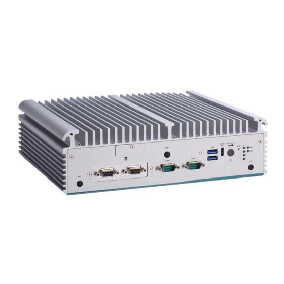
Fanless embedded system with LGA1700 socket ® 13th/12th Gen Intel Core™ i9/i7/i5/i3 or Celeron® eBOX671B-ALD-GbE ® processor, Intel R680E, 2 HDMI, DisplayPort, 6 USB, 4 LAN, and 9 to 36 VDC Please contact Axiomtek’s distributors immediately in case any abovementioned items are missing. Introduction... - Page 22 Series user’s Manual This page is intentionally left blank. Introduction...
-
Page 23: Section 2 Hardware Installation
Series user’s Manual SECTION 2 HARDWARE INSTALLATION The eBOX671B is convenient for various hardware configurations, such as CPU, DRAM, HDD (Hard Disk Drive), SSD (Solid State Drive), PCI Express Mini card modules and optional MXM graphic module. Section 2 contains guidelines for hardware installation. - Page 24 Series user’s Manual Step 4 Remove the warning label and disengage load lever. ⚫ Disengage load lever by pushing its hook down and then pulling it slightly outward. ⚫ Rotate load lever to open position at approximately 135°. ⚫...
- Page 25 Series user’s Manual Step 5 CPU installation steps: ⚫ Lift processor package from shipping media by grasping the substrate edges. ⚫ Scan the processor package gold pads for any presence of foreign material. ⚫ Locate connection 1 indicator on the processor which aligns with connection 1 indicator chamfer on the socket, and notice processor keying features that line up with posts along socket walls.
- Page 26 Series user’s Manual Step 6 Align pins of the CPU with pin holes of the socket. While installing the CPU, pay attention to the CPU’s orientation by aligning the arrow mark on the CPU with the arrow key on the socket.
- Page 27 Series user’s Manual 2.2 Installation of DRAM Module Step 1 Turn off the system and unplug the power cord. Step 2 Loosen four screws of the top heatsink & two screws of the front/rear panel. Step 3 Remove the top heatsink and located the dual SO-DIMM socket.
- Page 28 Series user’s Manual Step 5 Use a pair of tweezers to peel one side of protective film away from the remaining thermal pad and hold the edge of the DRAM and insert it into the DRAM notch at an angle of approximately 30 degrees, and then gently press it down until the latches are buckled.
-
Page 29: Installation Of 2.5" Sata Device
Series user’s Manual 2.3 Installation of 2.5" SATA Device Step 1 Turn off the system and unplug the power cord. Step 2 Loosen three screws to remove bottom cover and locate two SSD/HDD within the red line as marked. -
Page 30: Installation Of M.2 Key B Mini Pcie Module (Cn20)
Series user’s Manual 2.4 Installation of M.2 Key B Mini PCIe Module (CN20) The eBOX671B equipped with an M.2 Key B 3052 socket for users to install an 5G module. Step 1 Turn off the system and unplug the power cord. - Page 31 Series user’s Manual Step 5 Remove the antenna cover from system, fix the SMA connector of the IPEX-to-SMA cable to one of the five antenna apertures on either front panel of back panel. Step 6 Put the bottom cover and fasten all screws back onto the system.
-
Page 32: Installation Of Mini Pcie Module (Cn23)
Series user’s Manual 2.5 Installation of Mini PCIe Module (CN23) The eBOX671B provides one full-size mini-PCIe socket with SIM card support. Customers can use this socket for install wireless modules or flexible IO modules to expand functions for eBOX671B. - Page 33 Series user’s Manual Step 5 Connect the cable to the module and assemble I/O connector to fix the I/O bracket then fasten dual screws of the Flexible I/O Window. Step 6 Put the bottom cover and fasten all screws back onto the system.
- Page 34 Series user’s Manual Step 4 Insert the LTE mPCIe module on a 45 degree angle into the mPCIe slot and secure the module with M3x2 screw. Step 5 Remove the antenna cover from system, fix the SMA connector of the IPEX-to-SMA cable to one of the five antenna apertures on either front panel of back panel.
-
Page 35: Installation Of M.2 Key E Mini Pcie Module (Cn19)
Series user’s Manual 2.6 Installation of M.2 Key E Mini PCIe Module (CN19) The eBOX671B equipped with an M.2 Key E 2230 socket for users to install an Wi- Fi 6E wireless module. Step 1 Turn off the system and unplug the power cord. - Page 36 Series user’s Manual Step 5 Remove the antenna cover from system, fix the SMA connector of the IPEX-to-SMA cable to one of the five antenna apertures on either front panel of back panel. Step 6 Put the bottom cover and fasten all screws back onto the system.
-
Page 37: Installation Of Optional Mxm Graphic Module (Scn4)
Series user’s Manual 2.7 Installation of Optional MXM Graphic Module (SCN4) The eBOX671B,equipped with a MXM 3.1 type A slot for users to install a fan-less GPU module. Step 1 Turn off the system and unplug the power cord. - Page 38 Series user’s Manual Step 6 Fasten the copper thermal pad onto the top heat sink , and please make sure that the notch as red marked is facing up. Step 7 Fasten the top cover back to complete the MXM module installation.
-
Page 39: Installation Of Nvme Ssd Module (Scn1)
Series user’s Manual 2.8 Installation of NVMe SSD Module (SCN1) The eBOX671B equipped with an M.2 Key M 2280 socket (PCIex4 signal) for users to install an NVMe SSD module. Please refer to the following instructions and illustrations for the installation of the NVMe SSD module. -
Page 40: Installation Of External Fan Kit (Cn2)
Series user’s Manual 2.9 Installation of External FAN kit (CN2) The eBOX671B supports optional FAN kit for MXM module if users need better operation temperature, please follow the following instruction to install the FAN kit. The Ebox671B is designed with an optional external fan kit to enhance GPU computing performance and extend the operating temperature range. - Page 41 Series user’s Manual Step 5 remove the FAN connector cover. Step 6 Connector the fan cable to the fan connector of the system and put the cover back. Hardware Installation...
- Page 42 Series user’s Manual This page is intentionally left blank. Hardware Installation...
-
Page 43: Section 3 Jumper & Connector Settings
Series user’s Manual SECTION 3 JUMPER & CONNECTOR SETTINGS Proper jumper settings configure the eBOX671B to meet various application needs. Hereby all jumpers settings along with their default settings are listed for devices onboard. 3.1 Locations of Jumpers & Connectors PSB503 Top View Jumper &... - Page 44 Series user’s Manual PSB503 Bottom View 【Note】: It is strongly recommended that any unmentioned jumper settings should not be modified without instructions by Axiomtek FAEs. Any modifications without instructions might cause system failure. Jumper & Connector Settings...
-
Page 45: Summary Of Jumper Settings
Series user’s Manual 3.2 Summary of Jumper Settings Proper jumper settings configure the eBOX671B to meet various application purposes. A table of all jumpers and their default settings is listed below. 【Note】: How to setup Jumpers That a cap on a jumper is to “close” the jumper, whereas that offs a jumper is to “open” the jumper. -
Page 46: Connectors
Series user’s Manual 3.3 Connectors Please refer to below connector table to get their pin assignments. External Connectors Sections DC-in Phoenix Power Connector (CN1) 3.3.1 HDMI Connector (CN28, CN34) 3.3.2 DisplayPort Connector (CN28) 3.3.3 Serial Port Connector (CN4, CN5) 3.3.4... -
Page 47: Dc-In Phoenix Power Connector (Cn1)
Series user’s Manual 3.3.1 DC-in Phoenix Power Connector (CN1) The system supports 9~48V Phoenix DC-in connector for system power input. Pins Signals 3.3.2 HDMI Connector (CN28, CN34) The HDMI (High-Definition Multimedia Interface) is a compact digital interface which is capable of transmitting high-definition video and high-resolution audio over a single cable. -
Page 48: Displayport++ 1.2A Connector (Cn28)
Series user’s Manual 3.3.3 DisplayPort++ 1.2a Connector (CN28) eBOX671B supports one DisplayPort outputs. Pins Signals Pins Signals DPB_LANE0 DPB_LANE3# DPB_LANE0# Detect Pin DPB_LANE1 DPB_AUX DPB_LANE1# DPB_LANE2 DPB_AUX# DPB_HPDE DPB_LANE2# DPB_LANE3 +3.3V 3.3.4 DisplayPort Connector (CN27)(optional, via MXM module) eBOX671B support optional two DisplayPort outputs via MXM module. -
Page 49: Serial Port Connector (Cn4,Cn5)
Series user’s Manual 3.3.5 Serial Port Connector (CN4,CN5) The system has two serial ports. COM1~COM2 are RS-232/422/485 ports. COM3~COM4 are RS-232 Please refer to Chapter 4 for the detail of BIOS setting. *Baud rate support up to 115200* Pins... -
Page 50: Usb 3.2 Connector (Cn29, Cn8, Cn7)
Series user’s Manual 3.3.6 USB 3.2 Connector (CN29, CN8, CN7) The system has six USB port, six port compliant with USB 3.2 gen2 (10GB/s), and ideally for installing USB peripherals such as scanner, camera, and USB devices, etc. Pins... -
Page 51: Atx Power On/Off (Sw2)
Series user’s Manual 3.3.8 ATX Power On/Off (SW2) The ATX power button is on the I/O side. It can allow users to control eBOX671B power on/off. Functions Descriptions Turn on/off system Keep system status 3.3.9 Reset Switch (SW3) The Reset button can allow users to reset eBOX671B system. -
Page 52: Sata Connector (Cn10 & Cn15)
Series user’s Manual 3.3.12 SATA Connector (CN10 & CN15) These Serial Advanced Technology Attachment (Serial ATA or SATA) connectors are for high-speed SATA interfaces. They are computer bus interfaces for connecting to devices such as hard disk drives. This board has two SATA 3.0 ports with 6Gb/s performance. -
Page 53: Full-Size Pci Express Mini Card Slot (Cn23)
Series user’s Manual 3.3.15 Full-Size PCI Express Mini Card Slot (CN23) The eBOX671B supports one full-size PCI-Express Mini Card slot. CN23 is applying for PCI-Express or SATA (mSATA) via BIOS selection and USB signals; PCI- Express complies with PCI-Express Mini Card Spec. V1.2. Thus, users can install mSATA or WLAN/WWAN cards into this slot. -
Page 54: 3052 Key B Slot (Cn20)
Series user’s Manual 3.3.16 M.2 3052 Key B slot (CN20) The M.2 3052 Key B for 5G Module. Signal Signal Signal Signal +3.3V +3.3V USB_D+ USB_D- SATA_LED Key B Key B Key B Key B Key B Key B... -
Page 55: 2230 Key E Slot (Cn19)
Series user’s Manual 3.3.17 M.2 2230 Key E slot (CN19) The system comes with one M.2 Key E socket (PCIe & USB2.0) Pins Signals Pins Signals +3.3V_SBY USB_D+ +3.3V_SBY USB_D- M.2_BT_PCMCLK CNVI_WGR_DATA1_D- M.2_BT_PCMRST CNVI_WGR_DATA1_D+ M.2_BT_PCMIN M.2_BT_PCMOUT CNVI_WGR_DATA0_D- CNVI_WGR_DATA0_D+ UART_BT_WAKE-... -
Page 56: 2230 Key M Slot (Scn1)
Series user’s Manual CNVI_WT_DATA0_D+ CNVI_WT_CLK_D- +3.3V_SBY CNVI_WT_CLK_D+ +3.3V_SBY 3.3.18 M.2 2230 Key M slot (SCN1) The system comes with one M.2 Key E socket (PCIe & USB2.0) 3.3.19 HD Audio Digital Header (CN32, CN33) This audio jack support for Audio Mic-In and Line-out. -
Page 57: Digital I/O (Cn13 And Cn14) (Optional)
Series user’s Manual 3.3.20 Digital I/O (CN13 and CN14) (optional) The system is equipped with 16bit programmable Digital I/O, please refer to the following table to get default pin define. Default is 4in/4out. The digital I/O can be configured to control cash drawers and sense warning signals from an Uninterrupted Power System (UPS) or perform store security control. - Page 58 Series user’s Manual This page is intentionally left blank. Jumper & Connector Settings...
-
Page 59: Section 4 Bios Setup Utility
Series user’s Manual SECTION 4 BIOS SETUP UTILITY This section provides users with detailed descriptions in terms of how to set up basic system configurations through the BIOS setup utility. 4.1 Starting To enter the setup screens, follow the steps below: Turn on the computer and press the <Del>... -
Page 60: Main Menu
Series user’s Manual 4.3 Main Menu The Main Menu screen is the first screen users see when entering the setup utility. Users can always return to the Main setup screen by selecting the Main tab. System Time/Date can be set up as described below. -
Page 61: Advanced Menu
Series user’s Manual 4.4 Advanced Menu The Advanced menu also allows users to set configuration of the CPU and other system devices. Users can select any items in the left frame of the screen to go to sub menus: ►... - Page 62 Series user’s Manual Smart Ignition Management Press Enter to access the sub-menu. Calculated based on the 24-hour military-time clock. BIOS menu item Description Ignition Management Enabled Switch to ACC mode *Note: IGN signal will only be triggered when DCIN Terminal Block 4-Pin IGN relates to VCC.
- Page 63 Series user’s Manual System will not turn on automatically when power is connected or when power resumes from a power failure Advance Setting Set system on/off timing and voltage threshold levels Save Settings Save the current settings Restore Factory...
- Page 64 Series user’s Manual BIOS menu item Description Activate Voltage Trigger The system only turns on when the voltage delivered by the power source is higher than the value you set here. Low Voltage Trigger The system will begin countdown stage once voltage drops below the value you set here.
- Page 65 Series user’s Manual ACPI Settings Use this screen to select options for the ACPI configuration and change the value of the selected option. A description of the selected item appears on the right side of the screen. ACPI Sleep State When the sleep button is pressed, the system will be in the ACPI sleep state.
- Page 66 Series user’s Manual Trust Computing If users install a security device, such as TPM, users will see the following information for the TPM device and status. BIOS Setup Utility...
- Page 67 Series user’s Manual Storage Configuration This screen shows the CPU version and its detailed information. BIOS Setup Utility...
- Page 68 Series user’s Manual NVMe Configuration This screen shows NVMe device information. BIOS Setup Utility...
- Page 69 Series user’s Manual AMT Configurations Users can use this screen to configure AMT parameters. ® Intel Enable or disable Intel Active Management Technology BIOS Extension. ® The default is enabled. BIOS Setup Utility...
- Page 70 Series user’s Manual F81966 Super IO Configurations Use this screen to select options for the F81966 Super IO Configurations and change the value of the selected option. A description of the selected item appears on the right side of the screen.
- Page 71 Series user’s Manual Serial Port 1 Serial Port 2 BIOS Setup Utility...
- Page 72 Series user’s Manual Serial Port 3 Serial Port 4 BIOS Setup Utility...
- Page 73 Series user’s Manual Hardware Monitor This screen monitors hardware health status. This screen displays the temperature of system and CPU as well as system voltages (VCORE, +3V STBY, +5V STBY and +5V). BIOS Setup Utility...
- Page 74 Series user’s Manual USB Configurations This screen shows USB configuration. BIOS Setup Utility...
- Page 75 Series user’s Manual Device Configurations Users can use this screen to configure Device configurations. BIOS Setup Utility...
- Page 76 Series user’s Manual BIOS Setup Utility...
- Page 77 Series user’s Manual BIOS Setup Utility...
- Page 78 Series user’s Manual BIOS Setup Utility...
-
Page 79: Chipset Menu
Series user’s Manual 4.5 Chipset Menu The Chipset menu allows users to change the advanced chipset settings. Users can select any of the items in the left frame of the screen to go to the sub menus: ► System Agent (SA) Configurations ►... - Page 80 Series user’s Manual System Agent (SA) Configurations VT-d VT-d capability. Above 4GB MMIO BIOS assignment Enable/Disable above 4GB Memory Mapped IO BIOS assignment. This is enabled automatically when Aperture Size is set to 2048MB. Graphics Configuration Use this item to configure internal graphics controller.
- Page 81 Series user’s Manual Graphic Configurations Internal Graphics Keep IGFX enabled based on the setup options. BIOS Setup Utility...
- Page 82 Series user’s Manual PCH-IO Configurations This screen allows users to set PCH parameters. Wake on LAN Enable Enable or disable integrated LAN to wake the system. PCIE/SATA Switch Enable or disable integrated LAN to wake the system. BIOS Setup Utility...
- Page 83 Series user’s Manual Security Menu Administrator Password This item indicates whether an administrator password has been set (installed or uninstalled). User Password This item indicates whether a user password has been set (installed or uninstalled). BIOS Setup Utility...
- Page 84 Series user’s Manual Secure Boot Mode Use this item to set UEFI Secure Boot Mode to Standard mode or Custommode. This change is effective after save. After reset, this mode will return to Standardmode. Restore Factory Keys Use this item to force System to User Mode, to install factory default SecureBoot key databases.
-
Page 85: Boot Menu
Series user’s Manual 4.6 Boot Menu The Boot menu allows users to change boot options of the system. Setup Prompt Timeout Use this item to set up number of seconds to wait for setup activation key where 65535(0xFFFF) means indefinite waiting. -
Page 86: Save & Exit Menu
Series user’s Manual 4.7 Save & Exit Menu The Save & Exit menu allows users to load system configurations with optimal or fail-safe default values. Save Changes and Exit When users have completed the system configuration changes, select this option to leave Setup and return to Main Menu. - Page 87 Series user’s Manual Save Changes Having completed the system configuration changes, select this option to save changes. Select Save Changes from the Save & Exit menu and press <Enter>. Select Yes to save changes. Discard Changes Select this option to quit Setup without making any permanent changes to the system configurations.
- Page 88 Series user’s Manual This page is intentionally left blank. BIOS Setup Utility...
-
Page 89: Appendix Awatchdog Timer
Series user’s Manual APPENDIX A WATCHDOG TIMER A.1 About Watchdog Timer Software stability is major issue in most application. Some embedded systems are not watched by human for 24 hours. It is usually too slow to wait for someone to reboot when computer hangs. - Page 90 Series user’s Manual LONG WDTDATA = 0; typedef ULONG(*LPFNDLLGETIOSPACE)(ULONG); LPFNDLLGETIOSPACE lpFnDll_Get_IO; typedef void(*LPFNDLLSETIOSPACE)(ULONG, ULONG); LPFNDLLSETIOSPACE lpFnDll_Set_IO; int _tmain(int argc, _TCHAR* argv[]) int unit = 0; int WDTtimer = 0; if (hinstLibDLL == NULL) hinstLibDLL = LoadLibrary(TEXT("diodll.dll")); if (hinstLibDLL == NULL) //MessageBox("Load diodll dll error", "", MB_OK);...
- Page 91 Series user’s Manual //set LDN07 FA 10 to 11 lpFnDll_Set_IO(0x2e, 0xFA); WDTDATA = lpFnDll_Get_IO(0x2f); WDTDATA = setbit(WDTDATA, 0); lpFnDll_Set_IO(0x2f, WDTDATA); if (unit == 1) lpFnDll_Set_IO(0x2e, 0xF6); lpFnDll_Set_IO(0x2f, WDTtimer); //start watchdog counting lpFnDll_Set_IO(0x2e, 0xF5); WDTDATA = lpFnDll_Get_IO(0x2f); WDTDATA = setbit(WDTDATA, 5);...
- Page 92 Series user’s Manual This page is intentionally left blank. Programmable LED...
-
Page 93: Appendix Bconfiguring Sata For Raid
Series user’s Manual APPENDIX B CONFIGURING SATA FOR RAID Configuring SATA Hard Drive(s) for RAID ® (Controller: Intel R680E) Before you begin the SATA configuration, please prepare: ⚫ Two SATA hard drives (to ensure optimal performance, it is recommended that you use two hard drives with identical model and capacity). - Page 94 Series user’s Manual Turn on your system, and then press the <Del> button to enter BIOS Setup during running 2.1. POST (Power-On Self-Test). If you want to create RAID, just go to the Advanced Settings menu\VMD Configuration, enabled the “Enable VMD controller”, save and exit the BIOS Setup.
- Page 95 Series user’s Manual After restart, press <Del> button to enter BIOS Setup Menu. In Advanced Page, select 2.3. Intel(R) Rapid Storage Technology. Select the storage that to be used to RAID function. 2.4. Configuring SATA for RAID...
- Page 96 Series user’s Manual And press <Create volume> 2.6 Install OS. Click Load Driver. Configuring SATA for RAID...
- Page 97 Series user’s Manual 2.7 Click Browse, Find the VMD File and choose "f6vmdflpy.x64". Configuring SATA for RAID...
- Page 98 Series user’s Manual 2.8 Press NextStep. 2.9 The storage will be detected after the previous steps. Configuring SATA for RAID...
Need help?
Do you have a question about the eBOX671B Series and is the answer not in the manual?
Questions and answers