Table of Contents
Advertisement
Quick Links
Advertisement
Chapters
Table of Contents

Related Manuals for AXIOMTEK eBOX710A Series


Summary of Contents for AXIOMTEK eBOX710A Series
- Page 1 Series Embedded System User’s Manual...
-
Page 2: Disclaimers
Axiomtek does not make any commitment to update any information in this manual. Axiomtek reserves the right to change or revise this document and/or product at any time without notice. No part of this document may be reproduced, stored in a retrieval system, or transmitted in any forms or by any means, electronic, mechanical, photocopying, recording, among others, without prior written permissions of Axiomtek Co., Ltd. -
Page 3: Safety Precautions
Safety Precautions Before getting started, please read the following important safety precautions. The eBOX710A does not come with an operating system which must be loaded first before installation of any software into the computer. Be sure to ground yourself to prevent static charge when installing any internal components. -
Page 4: Classifications
Classifications Degree of production against electric shock: not classified Degree of protection against ingress of water: IP40 Equipment not suitable for use in the presence of a flammable anesthetic mixture with air, oxygen or nitrous oxide. Mode of operation: Continuous... -
Page 5: General Cleaning Tips
General Cleaning Tips Please keep the following precautions in mind while understanding the details fully before and during any cleaning of the computer and any components within. A piece of dry cloth is ideal to clean the device. Be cautious of any tiny removable components when using a vacuum cleaner to absorb dirt on the floor. -
Page 6: Scrap Computer Recycling
Scrap Computer Recycling Please inform the nearest Axiomtek distributor as soon as possible for suitable solutions in case computers require maintenance or repair; or for recycling in case computers are out of order. Trademarks Acknowledgments Axiomtek is a trademark of Axiomtek Co., Ltd. -
Page 7: Table Of Contents
Table of Contents Disclaimers ......................ii Safety Precautions ....................iii Classifications ....................... iv General Cleaning Tips ................... v Scrap Computer Recycling ................... vi SECTION 1 INTRODUCTION................. 1 General Descriptions ................. 1 System Specifications ............... 3 1.2.1 CPU ........................3 1.2.2 I/O System ...................... - Page 8 Starting ..................... 33 Navigation Keys ................33 Main Menu ..................34 Advanced Menu ................35 Chipset Menu ................... 48 Boot Menu ..................53 Save & Exit Menu ................54 APPENDIX A WATCHDOG TIMER ............. 57 About Watchdog Timer ..............57 Sample Program ................
-
Page 9: Section 1 Introduction
Series user’s Manual SECTION 1 INTRODUCTION This section contains general information and detailed specifications of the eBOX710A.Section 1 consist of the following sub-sections: ◼ General Descriptions ◼ System Specifications ◼ Dimensions ◼ I/O Outlets ◼ Packing List ◼ Model List 1.1 General Descriptions... - Page 10 Series user’s Manual Features Core™ i9/i7/i5/i3 or Celeron ® ® ® ⚫ LGA1200 10th/11th gen Intel with Intel H420E chipset (Comet Lake-S) ⚫ Dual 2.5" SATA HDD drive bays ⚫ 2 HDMI and 1 DisplayPort for dual view ⚫...
-
Page 11: System Specifications
Series user’s Manual 1.2 System Specifications 1.2.1 CPU ⚫ CPU (10th gen, 35W/65W) Core™ i9/i7/i5/i3 & Celeron ® ® ◼ LGA1200 10th/11th gen Intel processors Core™ i9-10900T Processor (35W) ® ◼ Intel Core™ i7-10700 (65W) ◼ ® Intel Core™ i7-10700E (65W) ◼... -
Page 12: System Specifications
7 kg (15.43 lb) with package ⚫ Dimension ◼ 280 mm (11.02") (W) x 210 mm (8.26") (D) x 80. 5 mm (3.16") (H) 1.2.4 Driver CD Contents Please download the following eBOX710A drivers from the Axiomtek official website. ⚫ Ethernet ⚫ Chipset ⚫... -
Page 13: Dimensions
Series user’s Manual 1.3 Dimensions The following diagrams show dimensions and outlines of the eBOX710A. 1.3.1 System Dimensions Introduction... -
Page 14: Wall-Mount Bracket Dimensions
Series user’s Manual 1.3.2 Wall-mount Bracket Dimensions Users can get 6pcs truss head M3*6L screws for fixing the wall mount kit from the accessories box. Note: When users install wall mount kit, please turn the LAN ports side outlet towards the floor. - Page 15 Series user’s Manual Wall-mount Bracket Assembly Drawing Users can get 6pcs truss head M3*6L screws for fixing the wall mount kit from the accessories box. 【Note】: If users install the screws in drywall, use the hollow wall anchors to...
-
Page 16: Din-Rail Bracket Dimensions
Series user’s Manual 1.3.3 Din-Rail Bracket Dimensions Users can get 6pcs truss head M3*6L screws for fixing the wall mount kit from the accessory box. Introduction... - Page 17 Series user’s Manual Din-Rail Bracket Assembly Drawing Users can get 6pcs truss head M3*6L screws for fixing the wall mount kit from the accessory box. Introduction...
-
Page 18: I/O Outlets
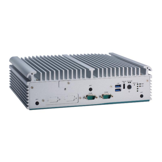
Series user’s Manual 1.4 I/O Outlets The following figures show I/O outlets on the eBOX710A. Front View 1 x Flexible IO window LEDs RS232(COM4) 1 x Reset switch RS232(COM3) 1 x ATX/AT quick switch 2 x USB 3.2 Gen 1... - Page 19 Series user’s Manual Rear View 4 x GbE LAN 1 x Grounding screw 1 x Phoenix type power connector PCIe x4 expansion slot (9-48VDC) 1 x USB 2.0 1 x RS232/422/485 (COM2) 1 x USB 3.2 Gen 1 2 x HDMI...
-
Page 20: Packing List
Core™ i9/i7/i5/ i3 or Celeron ® eBOX710A-CML-PCIe Processor, Intel ® H420E, 2 HDMI, 1 DisplayPort, 6 USB, 4 LAN, PCIe x4 expansion slot and 9 to 48 VDC Please contact Axiomtek’s distributors immediately in case any abovementioned items are missing. Introduction... -
Page 21: Section 2 Hardware Installation
Series user’s Manual SECTION 2 HARDWARE INSTALLATION The eBOX710A is convenient for various hardware configurations, such as CPU, DRAM, HDD (Hard Disk Drive), SSD (Solid State Drive), PCI Express Mini card modules . Section 2 contains guidelines for hardware installation. - Page 22 Series user’s Manual Step 4 CPU installation steps: ⚫ Lift processor package from shipping media by grasping the substrate edges. ⚫ Scan the processor package gold pads for any presence of foreign material. ⚫ Locate connection 1 indicator on the processor which aligns with connection 1 indicator chamfer on the socket, and notice processor keying features that line up with posts along socket walls.
- Page 23 Series user’s Manual Step 5 Align pins of the CPU with pin holes of the socket. While installing the CPU, pay attention to the CPU’s orientation by aligning the arrow mark on the CPU with the arrow key on the socket.
-
Page 24: Installation Of 2.5" Sata Device
Series user’s Manual 2.2 Installation of 2.5" SATA Device Step 1 Turn off the system and unplug the power cord. Step 2 Loosen three screws to remove bottom cover and Locate two SSD/HDD within the red line as marked. -
Page 25: Installation Of M.2 Mini Pcie Module (Cn26)
Series user’s Manual 2.3 Installation of M.2 Mini PCIe Module (CN26) Step 1 Turn off the system and unplug the power cord. Step 2 Loosen three screws to remove bottom cover and locate M.2 mini card slot within the red line as marked. -
Page 26: Installation Of Mini Pcie Module (Full-Size)(Cn17,Cn20)
Series user’s Manual 2.4 Installation of Mini PCIe Module (Full-size)(CN17,CN20) Step 1 Turn off the system and unplug the power cord. Step 2 Loosen three screws to remove bottom cover and locate PCIe mini card slot within the red line as marked. -
Page 27: Section 3 Jumper & Connector Settings
Series user’s Manual SECTION 3 JUMPER & CONNECTOR SETTINGS Proper jumper settings configure the eBOX710A to meet various application needs. Hereby all jumpers settings along with their default settings are listed for devices onboard. 3.1 Locations of Jumpers & Connectors PSB503 Top View Jumper &... - Page 28 Series user’s Manual PSB503 Bottom View 【 Note 】 : It is strongly recommended that any unmentioned jumper settings should not be modified without instructions by Axiomtek FAEs. Any modifications without instructions might cause system failure. Jumper & Connector Settings...
-
Page 29: Summary Of Jumper Settings
Series user’s Manual 3.2 Summary of Jumper Settings Proper jumper settings configure the eBOX710A to meet various application purposes. A table of all jumpers and their default settings is listed below. Jumpers Descriptions Settings Restore BIOS Optimal Defaults Short 1-2 Default: Normal Operation 【Note】: How to setup Jumpers... -
Page 30: Connectors
Series user’s Manual 3.3 Connectors Please refer to below connector table to get their pin assignments. External Connectors Sections DC-in Phoenix Power Connector 3.3.1 HDMI Connector 3.3.2 DisplayPort Connector 3.3.3 Serial Port Connector 3.3.4 USB 3.2 Connector 3.3.5 Ethernet Connector 3.3.6... -
Page 31: Dc-In Phoenix Power Connector (Cn1)
Series user’s Manual 3.3.1 DC-in Phoenix Power Connector (CN1) The system supports 9~48V Phoenix DC-in connector for system power input. Pins Signals 3.3.2 HDMI Connector (CN7, CN8) The HDMI (High-Definition Multimedia Interface) is a compact digital interface which is capable of transmitting high-definition video and high-resolution audio over a single cable. -
Page 32: Displayport Connector (Cn4)
Series user’s Manual 3.3.3 DisplayPort Connector (CN4) eBOX710A supports one DisplayPort outputs. Pins Signals Pins Signals DPB_LANE0 DPB_LANE3# DPB_LANE0# Detect Pin DPB_LANE1 DPB_AUX DPB_LANE1# DPB_LANE2 DPB_AUX# DPB_HPDE DPB_LANE2# DPB_LANE3 +3.3V 3.3.4 Serial Port Connector (CN3)(CN18)(CN21) The system has two serial ports. COM1~COM2 are RS-232/422/485 ports. COM3~COM4 are RS-232 Please refer to Chapter 4 for the detail of BIOS setting. -
Page 33: Usb 3.2 Connector (Cn5, Cn6, Cn30)
Series user’s Manual 3.3.5 USB 3.2 Connector (CN5, CN6, CN30) The system has six USB port, five port compliant with USB 3.2 gen1 (5GB/s), one port compliant with USB 2.0 (480MB/s), and ideally for installing USB peripherals such as scanner, camera, and USB devices, etc. -
Page 34: Ethernet Connector (Lan1~Lan4)
Series user’s Manual 3.3.6 Ethernet Connector (LAN1~LAN4) The board has four RJ-45 Gbe ports connectors, LAN1 is designed by Intel i219LM and LAN2 to LAN4 are Intel i210-IT. Pins LAN Signal Pins LAN Signal MDI0+ MDI2+ MDI0- MDI2- MDI1+... -
Page 35: Remote Power Switch Connector (Pwrbt1)
Series user’s Manual 3.3.9 Remote Power Switch Connector (PWRBT1) One 2-pin connector output for remote power on/off switch. Functions Descriptions Short(1-2) Turn on/off system Open Keep system status 3.3.10 ATX/AT Quick Switch If you set ATX /AT switch to AT mode, the system will be automatically power on without pressing soft power button during power input;... -
Page 36: Sata Power Connector (Cn10,Cn11)
Series user’s Manual 3.3.12 SATA Power Connector (CN10,CN11) Based on CN10、CN11 to offer the SATA power for SATA 2.5" HDD/SSD. Pins Signals +12V level +5V level 3.3.13 SIM Card Slots (SCN1, CN22) The eBOX710A includes two SIM slots: SCN1 on top side of the system that support M.2 Key B (for CN26), CN22 on bottom side that support mini PCIe slot (for CN20). -
Page 37: Full-Size Pci Express Mini Card Slot (Cn17,Cn20)
Series user’s Manual 3.3.14 Full-Size PCI Express Mini Card Slot (CN17,CN20) The eBOX710A supports dual full-size PCI-Express Mini Card slots. CN17 and CN20 is applying for PCI-Express or SATA (mSATA) via BIOS selection and USB signals; PCI-Express complies with PCI-Express Mini Card Spec. V1.2. Thus, users can install mSATA or WLAN/WWAN cards into this slot. - Page 38 Series user’s Manual CN20 Pins Signals Signals WAKE# +3.3VSB No use +1.5V No use CLKREQ# SIM_PWR SIM_DATA REFCLK- SIM_CLK REFCLK+ SIM_RESET SIM_VPP No use No use W_DISABLE# PERST# PE_RXN3/mSATA +3.3VSB SATA_RXP PE_RXP3/mSATA SATA_RXN +1.5V SMB_CLK PE_TXN3/ mSATA SMB_DATA SATA_TXN...
-
Page 39: 3050/3052 Key B Slot (Cn26)
Series user’s Manual 3.3.15 M.2 3050/3052 Key B slot (CN26) The M.2 3050/3052 Key B for 5G Module. Pins Signals Pins Signals Pins Signals Pins Signals +3.3V +3.3V USB_D+ USB_D- Key B Key B Key B Key B Key B... -
Page 40: Intel ® Hd Audio Digital Header (Cn31, Cn32)(Optional)
Series user’s Manual ® 3.3.16 Intel HD Audio Digital Header (CN31, CN32)(Optional) These two audio jacks are ideal for Audio Mic-In and Audio Line-out. Signal Line Out Microphone In 3.3.17 Digital I/O (CN14 and CN16) (optional) The system is equipped with 16bit programmable Digital I/O, please refer to the following table to get default pin define. -
Page 41: Section 4 Bios Setup Utility
Series user’s Manual SECTION 4 BIOS SETUP UTILITY This section provides users with detailed descriptions in terms of how to set up basic system configurations through the BIOS setup utility. 4.1 Starting To enter the setup screens, follow the steps below: Turn on the computer and press the <Del>... -
Page 42: Main Menu
Series user’s Manual 4.3 Main Menu The Main Menu screen is the first screen users see when entering the setup utility. Users can always return to the Main setup screen by selecting the Main tab. System Time/Date can be set up as described below. -
Page 43: Advanced Menu
Series user’s Manual 4.4 Advanced Menu The Advanced menu also allows users to set configuration of the CPU and other system devices. Users can select any items in the left frame of the screen to go to sub menus: ►... - Page 44 Series user’s Manual ACPI Settings Use this screen to select options for the ACPI configuration and change the value of the selected option. A description of the selected item appears on the right side of the screen. ACPI Sleep State When the sleep button is pressed, the system will be in the ACPI sleep state.
- Page 45 Series user’s Manual Trust Computing If users install a security device, such as TPM, users will see the following information for the TPM device and status. BIOS Setup Utility...
- Page 46 Series user’s Manual CPU Configuration This screen shows the CPU version and its detailed information. Hyper-Threading It allows a hardware platform to run multiple operating systems separately and simultaneously, enabling one system to virtually function as several systems. Intel Virtualization Technology Enable or disable Intel Virtualization Technology.
- Page 47 Series user’s Manual SATA & RST Configuration In this Configuration menu, you can see the currently installed hardware in the SATA ports. During system boot up, the BIOS automatically detects the presence of SATA devices. SATA Mode Selection AHCI (Advanced Host Controller Interface) mode is how SATA controller(s) operate.
- Page 48 Series user’s Manual NCT6116D Super IO Configurations Use this screen to select options for the NCT6116D Super IO Configurations and change the value of the selected option. A description of the selected item appears on the right side of the ►...
- Page 49 Series user’s Manual Serial Port 1 Use this to set parameters of COM 1. COM Port type Use this item to set parameters related to serial ports COM1 (RS232/422/485) COM Port term type Use this item to select COM port terminal type.
- Page 50 Series user’s Manual Serial Port 2 Use this to set parameters of COM 2. COM Port type Use this item to set parameters related to serial ports COM 2 (RS232/422/485) COM Port term type Use this item to select COM port terminal type.
- Page 51 Series user’s Manual Serial Port 3 Serial Port 4 BIOS Setup Utility...
- Page 52 Series user’s Manual NCT6116D Hardware Monitor This screen monitors hardware health status. This screen displays the temperature of system and CPU as well as system voltages (VCORE, +3.3V, +5V STBY and +5V). BIOS Setup Utility...
- Page 53 Series user’s Manual PCH-FW Configuration This screen shows ME Firmware information. BIOS Setup Utility...
- Page 54 Series user’s Manual USB Configurations Users can use this screen to configure USB configurations. (換圖,拿掉 mass storage device) Legacy USB Support Enables Legacy USB support. AUTO option disables legacy support if no USB devices are connected. XHCI Hand-off This is a workaround for OSes without XHCI hand-off support. The XHCI ownership change should be claimed by XHCI driver.
- Page 55 Series user’s Manual Device Configurations Users can use this screen to configure Device configurations. BIOS Setup Utility...
-
Page 56: Chipset Menu
Series user’s Manual 4.5 Chipset Menu The Chipset menu allows users to change the advanced chipset settings. Users can select any of the items in the left frame of the screen to go to the sub menus: ► System Agent (SA) Configurations ►... - Page 57 Series user’s Manual System Agent (SA) Configurations VT-d VT-d capability. Memory Configuration Use this item to refer to the information related to system memory. BIOS Setup Utility...
- Page 58 Series user’s Manual Memory Configurations This screen shows the system memory information. BIOS Setup Utility...
- Page 59 Series user’s Manual PCH-IO Configurations This screen allows users to set PCH parameters. PCH LAN Controller Enable or disable onboard PCH LAN controller. Wake on LAN Enable Enable or disable integrated LAN to wake the system. HD Audio Configuration Enable or disable HD Audio.
- Page 60 Series user’s Manual Security Menu Administrator Password This item indicates whether an administrator password has been set (installed or uninstalled). User Password This item indicates whether a user password has been set (installed or uninstalled). BIOS Setup Utility...
-
Page 61: Boot Menu
Series user’s Manual 4.6 Boot Menu The Boot menu allows users to change boot options of the system. Setup Prompt Timeout Use this item to set up number of seconds to wait for setup activation key where 65535(0xFFFF) means indefinite waiting. -
Page 62: Save & Exit Menu
Series user’s Manual 4.7 Save & Exit Menu The Save & Exit menu allows users to load system configurations with optimal or fail-safe default values. Save Changes and Exit When users have completed the system configuration changes, select this option to leave Setup and return to Main Menu. - Page 63 Series user’s Manual Save Changes Having completed the system configuration changes, select this option to save changes. Select Save Changes from the Save & Exit menu and press <Enter>. Select Yes to save changes. Discard Changes Select this option to quit Setup without making any permanent changes to the system configurations.
- Page 64 Series user’s Manual This page is intentionally left blank. BIOS Setup Utility...
-
Page 65: Appendix Awatchdog Timer
Series user’s Manual APPENDIX A WATCHDOG TIMER A.1 About Watchdog Timer Software stability is major issue in most application. Some embedded systems are not watched by human for 24 hours. It is usually too slow to wait for someone to reboot when computer hangs. - Page 66 Series user’s Manual LONG WDTDATA = 0; typedef ULONG(*LPFNDLLGETIOSPACE)(ULONG); LPFNDLLGETIOSPACE lpFnDll_Get_IO; typedef void(*LPFNDLLSETIOSPACE)(ULONG, ULONG); LPFNDLLSETIOSPACE lpFnDll_Set_IO; int _tmain(int argc, _TCHAR* argv[]) int unit = 0; int WDTtimer = 0; if (hinstLibDLL == NULL) hinstLibDLL = LoadLibrary(TEXT("diodll.dll")); if (hinstLibDLL == NULL) //MessageBox("Load diodll dll error", "", MB_OK);...
- Page 67 Series user’s Manual //set LDN07 FA 10 to 11 lpFnDll_Set_IO(0x2e, 0xFA); WDTDATA = lpFnDll_Get_IO(0x2f); WDTDATA = setbit(WDTDATA, 0); lpFnDll_Set_IO(0x2f, WDTDATA); if (unit == 1) lpFnDll_Set_IO(0x2e, 0xF6); lpFnDll_Set_IO(0x2f, WDTtimer); //start watchdog counting lpFnDll_Set_IO(0x2e, 0xF5); WDTDATA = lpFnDll_Get_IO(0x2f); WDTDATA = setbit(WDTDATA, 5);...
- Page 68 Series user’s Manual This page is intentionally left blank Watchdog Timer...
Need help?
Do you have a question about the eBOX710A Series and is the answer not in the manual?
Questions and answers