Table of Contents
Advertisement
Quick Links
Advertisement
Table of Contents

Subscribe to Our Youtube Channel
Related Manuals for AXIOMTEK eBOX626A Series


Summary of Contents for AXIOMTEK eBOX626A Series
- Page 1 Series Embedded System User’s Manual...
-
Page 2: Disclaimers
Axiomtek does not make any commitment to update any information in this manual. Axiomtek reserves the right to change or revise this document and/or product at any time without notice. No part of this document may be reproduced, stored in a retrieval system, or transmitted in any forms or by any means, electronic, mechanical, photocopying, recording, among others, without prior written permissions of Axiomtek Co., Ltd. -
Page 3: Safety Precautions
Safety Precautions Before getting started, please read the following important safety precautions. The eBOX626A does not come with an operating system which must be loaded first before installation of any software into the computer. Be sure to ground yourself to prevent static charge when installing any internal components. -
Page 4: Classifications
Classifications Degree of production against electric shock: not classified Degree of protection against ingress of water: IP40 Equipment not suitable for use in the presence of a flammable anesthetic mixture with air, oxygen or nitrous oxide. Mode of operation: Continuous... -
Page 5: General Cleaning Tips
General Cleaning Tips Please keep the following precautions in mind while understanding the details fully before and during any cleaning of the computer and any components within. A piece of dry cloth is ideal to clean the device. Be cautious of any tiny removable components when using a vacuum cleaner to absorb dirt on the floor. -
Page 6: Scrap Computer Recycling
Scrap Computer Recycling Please inform the nearest Axiomtek distributor as soon as possible for suitable solutions in case computers require maintenance or repair; or for recycling in case computers are out of order. Trademarks Acknowledgments Axiomtek is a trademark of Axiomtek Co., Ltd. -
Page 7: Table Of Contents
Table of Contents Disclaimers ......................ii Safety Precautions ....................iii Classifications ....................... iv General Cleaning Tips ................... v Scrap Computer Recycling ................... vi SECTION 1 INTRODUCTION................. 1 General Descriptions ................. 1 System Specifications ............... 2 1.2.1 CPU ........................2 1.2.2 I/O System ...................... - Page 8 Navigation Keys ................35 Main Menu ..................36 Advanced Menu ................37 Chipset Menu ................... 49 Boot Menu ..................55 Save & Exit Menu ................56 viii...
-
Page 9: Section 1 Introduction
Series user’s Manual SECTION 1 INTRODUCTION This section contains general information and detailed specifications of the eBOX626A.Section 1 consist of the following sub-sections: ◼ General Descriptions ◼ System Specifications ◼ Dimensions ◼ I/O Outlets ◼ Packing List ◼ Model List 1.1 General Descriptions... -
Page 10: System Specifications
Series user’s Manual Reliable and Stable Design Processor J6412 (Elkhart Lake), along with ® ® The embedded system supports Intel Celeron high flexibility and multi-functional design that makes it the best solution for smart factory, AIOT, Edge Computing, Factory automation applications. -
Page 11: System Specifications
Series user’s Manual ⚫ Mini PCIe Interface ◼ 1 x full size internal PCI Express Mini Card slot (mSATA/SIM) (USB + PCIE + SATA) ◼ 1 x M.2 2230 E Key (PCIE + USB signal) ⚫ Storage ◼ 1 x 2.5" SATA HDD/SSD drive bay, up to 9.5mm height ◼... -
Page 12: Driver Cd Contents
Series user’s Manual 1.2.4 Driver CD Contents Please download the following eBOX626A drivers from the Axiomtek official website. ⚫ Chipset ⚫ Ethernet (i226-LM, i210-AT) ⚫ Chipset ⚫ Graphic ⚫ Serial Port ⚫ USB 3.1 ® ⚫ Intel ⚫ HD Audio ⚫... -
Page 13: Dimensions
Series user’s Manual 1.3 Dimensions The following diagrams show dimensions and outlines of the eBOX626A. 1.3.1 System Dimensions Introduction... -
Page 14: Wall-Mount Bracket Dimensions
Series user’s Manual 1.3.2 Wall-mount Bracket Dimensions Users can get 4pcs truss head M3*6L screws for fixing the wall mount kit from the accessories box. Note: When users install wall mount kit, please turn the LAN ports outlet side towards the floor. - Page 15 Series user’s Manual Wall-mount Bracket Assembly Drawing Users can get 4pcs truss head M3*6L screws for fixing the wall mount kit from the accessories box. 【Note】: If users tighten the screws in drywall, use the hollow wall anchors to...
-
Page 16: Din-Rail Bracket Dimensions
Series user’s Manual 1.3.3 Din-Rail Bracket Dimensions Users can get 8pcs truss head M3*4L screws for fixing the wall mount kit from the accessory box. Introduction... - Page 17 Series user’s Manual Din-Rail Bracket Assembly Drawing Users can get 8pcs truss head M3*4L screws for fixing the wall mount kit from the accessory box. Introduction...
-
Page 18: Vesa Mount Bracket Dimensions
Series user’s Manual 1.3.4 VESA Mount Bracket Dimensions Users can get 4pcs truss head M3*6L screws for fixing the wall mount kit from the accessory box. Introduction... - Page 19 Series user’s Manual VESA Mount Bracket Assembly Drawing Users can get 4pcs truss head M3*6L screws for fixing the wall mount kit from the accessory box. Introduction...
-
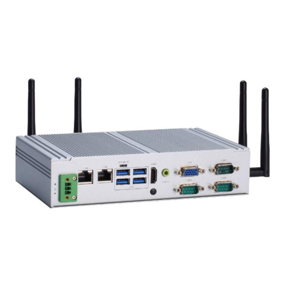
Page 20: I/O Outlets
Series user’s Manual 1.4 I/O Outlets The following figures show I/O outlets on the eBOX626A. Front View 2 x USB 2.0 1 x Power botton 2 x Antenna opening LEDs 1 x Remote power switch Introduction... - Page 21 Series user’s Manual Rear View 1 x Phoenix type power 1 x VGA connector(9-36VDC) 4 x USB 3.1 Gen 2 1 x Audio (Line-out) 1 x HDMI 1.4b (lockable) 1 x ATX/AT quick switch 1 x RS232 (COM3) 1 x 2.5G LAN (LAN 1, i226-LM)
-
Page 22: Packing List
DRAM thermal pad bracket x1 1.6 Model List Fanless Embedded System with Intel® Elkhart Lake eBOX626A-EL-C1 J6412 2.0 GHz, HDMI/VGA, 6 USB, 2 LAN, 3 COM, and 9 to 36 VDC Please contact Axiomtek’s distributors immediately in case any abovementioned items are missing. Introduction... -
Page 23: Section 2 Hardware Installation
Series user’s Manual SECTION 2 HARDWARE INSTALLATION The eBOX626A is convenient for various hardware configurations, such as DRAM, HDD (Hard Disk Drive), SSD (Solid State Drive), PCI Express Mini card, M.2 module. Section 2 contains guidelines for hardware installation. -
Page 24: Installation Of Memory Module
Series user’s Manual 2.2 Installation of Memory Module Step 1 Turn off the system and unplug the power cord. Step 2 Turn the system upside down to locate screws at the side of the system, and then loosen two screws and four-foot pads. - Page 25 Series user’s Manual Step 4 Insert the SO-DIMM into the socket and push the module down until it is locked in place by the two end latches. Step 5 Secure the DRAM bracket on top of the DRAM module with two screws.
-
Page 26: Installation Of M.2 Mini Pcie Module (Cn18)
Series user’s Manual 2.3 Installation of M.2 Mini PCIe Module (CN18) Step 1 Turn off the system and unplug the power cord. Step 2 Turn the system upside down to locate screws at the side of the system, and then loosen two screws and four foot pads. -
Page 27: Installation Of Mini Pcie Module (Full-Size)(Cn16)
Series user’s Manual 2.4 Installation of Mini PCIe Module (Full-size)(CN16) ※ Note: Please choose Mini card module or mSATA module either one to install. Step 1 Turn off the system and unplug the power cord. Step 2 Turn the system upside down to locate screws at the side of the system, and then loosen two screws and four foot pads. - Page 28 Series user’s Manual This page is intentionally left blank. Hardware Installation...
-
Page 29: Section 3 Jumper & Connector Settings
Series user’s Manual SECTION 3 JUMPER & CONNECTOR SETTINGS Proper jumper settings configure the eBOX626A to meet various application needs. Hereby all jumpers settings along with their default settings are listed for devices onboard. 3.1 Locations of Jumpers & Connectors PSB530 Top View Jumper &... - Page 30 Series user’s Manual PSB530 Bottom View 【 Note 】 : It is strongly recommended that any unmentioned jumper settings should not be modified without instructions by Axiomtek FAEs. Any modifications without instructions might cause system failure. Jumper & Connector Settings...
-
Page 31: Summary Of Jumper Settings
Series user’s Manual 3.2 Summary of Jumper Settings Proper jumper settings configure the eBOX626A to meet various application purposes. A table of all jumpers and their default settings is listed below. Jumpers Descriptions Settings Restore BIOS Optimal Defaults Short 1-2 Default: Normal Operation 【Note】: How to setup Jumpers... -
Page 32: Connectors
Series user’s Manual 3.3 Connectors Please refer to below connector table to get their pin assignments. External Connectors Sections DC-in Phoenix Power Connector (CN1) 3.3.1 HDMI Connector (CN22) 3.3.2 VGA Connector (CN28) 3.3.3 Serial Port Connector (CN27, CN13, CN15) 3.3.4... -
Page 33: Dc-In Phoenix Power Connector (Cn1)
Series user’s Manual 3.3.1 DC-in Phoenix Power Connector (CN1) The system supports 9~36V Phoenix DC-in connector for system power input. Pins Signals 3.3.2 HDMI Connector (CN22) The HDMI (High-Definition Multimedia Interface) is a compact digital interface which is capable of transmitting high-definition video and high-resolution audio over a single cable. -
Page 34: Vga Connector (Cn28)
Series user’s Manual 3.3.3 VGA Connector (CN28) eBOX626A supports one VGA (DB15) output. Pins Signals Pins Signals GREEN BLUE CRT_VCC CRT_VCC DDC_DATA Vsync Hsync DDC_CLK 3.3.4 Serial Port Connector (CN27, CN13, CN15) The system has three serial ports. COM1 is RS-232/422/485 ports. COM2~COM3 are RS-232. -
Page 35: Usb 3.2 Connector (Cn24, Cn25)
Series user’s Manual 3.3.5 USB 3.2 Connector (CN24, CN25) The system has six USB port, four port compliant with USB 3.2 gen1 (5GB/s), two port compliant with USB 2.0 (480MB/s), and ideally for installing USB peripherals such as scanner, camera, and USB devices, etc. -
Page 36: Ethernet Connector (Cn29, Cn21)
Series user’s Manual 3.3.6 Ethernet Connector (CN29, CN21) The eBOX626A has two RJ-45 connectors: LAN1 (CN29) and LAN2 (CN21). LAN1 is designed by Intel i226-LM and LAN2 is Intel i210-AT. Pin assignment for LAN1 (i226-LM, CN29) 2500/1000 100/10 Pins... -
Page 37: Atx Power On/Off (Sw1)
Series user’s Manual 3.3.7 ATX Power On/Off (SW1) The ATX power button is on the I/O side. It can allow users to control eBOX626A power on/off. Functions Descriptions Turn on/off system Keep system status 3.3.8 Remote Power Switch Connector (PWRBT1) One 2-pin connector output for remote power on/off switch. -
Page 38: Sata Connector (Cn10)
Series user’s Manual 3.3.11 SATA Connector (CN10) The Serial Advanced Technology Attachment (Serial ATA or SATA) connector is for high-speed SATA interfaces. It is computer bus interfaces for connecting to devices such as hard disk drives. This board has one SATA 3.0 ports with 6Gb/s performance. -
Page 39: Full-Size Pci Express Mini Card Slot (Cn16)
Series user’s Manual 3.3.13 Full-Size PCI Express Mini Card Slot (CN16) The eBOX626A supports one full-size PCI-Express Mini Card slot. CN16 is applying for PCI-Express or SATA (mSATA) via BIOS selection and USB signals; PCI- Express complies with PCI-Express Mini Card Spec. V1.2. Thus, users can install mSATA or WLAN/WWAN cards into this slot. -
Page 40: 2230 Key E Slot (Cn18)
Series user’s Manual 3.3.14 M.2 2230 Key E slot (CN18) The M.2 2230 Key E for WIFI Module. Pins Signals Pins Signals Pins Signals Pins Signals +3.3V USB_D+ +3.3V USB_D- CONNECTOR KEY E CONNECTOR CONNECTOR CONNECTOR CONNECTOR KEY E... -
Page 41: Intel Hd Audio Digital Header (Cn26)
Series user’s Manual ® 3.3.15 Intel HD Audio Digital Header (CN26) The audio jack is ideal for Audio Line-out. Signal Line Out Jumper & Connector Settings... - Page 42 Series user’s Manual This page is intentionally left blank. Jumper & Connector Settings...
-
Page 43: Section 4 Bios Setup Utility
Series user’s Manual SECTION 4 BIOS SETUP UTILITY This section provides users with detailed descriptions in terms of how to set up basic system configurations through the BIOS setup utility. 4.1 Starting To enter the setup screens, follow the steps below: Turn on the computer and press the <Del>... -
Page 44: Main Menu
Series user’s Manual 4.3 Main Menu The Main Menu screen is the first screen users see when entering the setup utility. Users can always return to the Main setup screen by selecting the Main tab. System Time/Date can be set up as described below. -
Page 45: Advanced Menu
Series user’s Manual 4.4 Advanced Menu The Advanced menu also allows users to set configuration of the CPU and other system devices. Users can select any items in the left frame of the screen to go to sub menus: ►... - Page 46 Series user’s Manual Trust Computing If users install a security device, such as TPM, users will see the following information for the TPM device and status. BIOS Setup Utility...
- Page 47 Series user’s Manual CPU Configuration This screen shows the CPU version and its detailed information. Intel Virtualization Technology Enable or disable Intel Virtualization Technology. When enabled, a VMM (Virtual Machine Mode) can utilize the additional hardware capabilities. It allows a platform to run multiple operating systems and applications independently, hence enabling a single computer system to work as several virtual systems.
- Page 48 Series user’s Manual Storage Configuration This screen allows users to select options for SATA Configuration, and change the value of the selected option. BIOS Setup Utility...
- Page 49 Series user’s Manual SATA Controller Highlight this item to enable or disable SATA Controller. BIOS Setup Utility...
- Page 50 Series user’s Manual USB Configurations Display all detected USB devices. BIOS Setup Utility...
- Page 51 Series user’s Manual F81966 Super IO Configurations Use this screen to select options for the F81966 Super IO Configurations and change the value of the selected option. A description of the selected item appears on the right side of the screen.
- Page 52 Series user’s Manual Serial Port 1 Use this to set parameters of COM 1 (RS232422/485). Serial Port Enable or disable serial port 1. The optimal setting for base I/O address is 3F8h and for interrupt request address is IRQ4.
- Page 53 Series user’s Manual Serial Port 2 Use this to set parameters of COM 2 (RS-232). Serial port Enable or disable serial port 2. The optimal setting for base I/O address is 2F8h and for interrupt request address is IRQ3.
- Page 54 Series user’s Manual Serial Port 3 Use this to set parameters of COM 3 (RS232). Serial port Enable or disable serial port 3. The optimal setting for base I/O address is 3E8h and for interrupt request address is IRQ7.
- Page 55 Series user’s Manual Hardware Monitor This screen monitors hardware health status. This screen displays the temperature of system and CPU as well as system voltages (VBAT, 5VSBY, 5VS, VCC3V and VSB5V). BIOS Setup Utility...
- Page 56 Series user’s Manual DIO Configuration Users can adjust the option 8-CH DIO default setting via this page. eBOX626A doesn’t support 8-CH DIO for standard version, users can order the DIO cable kit then change the option port (COM 3) to support 8-CH TTL DIO.
-
Page 57: Chipset Menu
Series user’s Manual 4.5 Chipset Menu The Chipset menu allows users to change the advanced chipset settings. Users can select any of the items in the left frame of the screen to go to the sub menus: ► System Agent (SA) Configurations ►... - Page 58 Series user’s Manual Mini Card Function Choose PCIE Mini Card as PCIE or mSATA BIOS Setup Utility...
- Page 59 Series user’s Manual SMBus Interface Choose PCIE Mini Card support SMBus Interface only for AX module BIOS Setup Utility...
- Page 60 Series user’s Manual Security Menu Administrator Password This item indicates whether an administrator password has been set (installed or uninstalled). User Password This item indicates whether a user password has been set (installed or uninstalled). Secure Boot Secure Boot feature is Active if Secure Boot is Enabled or Disable.
- Page 61 Series user’s Manual Secure Boot Use this item to enable or disable support for Secure Boot. Secure Boot Mode Secure Boot mode options: Standard or Custom. In Custom mode, Secure Boot Policy variables can be configured by a physically...
- Page 62 Series user’s Manual Key management Install factory default Secure Boot key the platform rest and while the System is in Setup mode. BIOS Setup Utility...
-
Page 63: Boot Menu
Series user’s Manual 4.6 Boot Menu The Boot menu allows users to change boot options of the system. Setup Prompt Timeout Use this item to set up number of seconds to wait for setup activation key where 65535(0xFFFF) means indefinite waiting. -
Page 64: Save & Exit Menu
Series user’s Manual 4.7 Save & Exit Menu The Save & Exit menu allows users to load system configurations with optimal or fail-safe default values. Save Changes and Exit When users have completed the system configuration changes, select this option to leave Setup and return to Main Menu. - Page 65 Series user’s Manual Save Changes Having completed the system configuration changes, select this option to save changes. Select Save Changes from the Save & Exit menu and press <Enter>. Select Yes to save changes. Discard Changes Select this option to quit Setup without making any permanent changes to the system configurations.
- Page 66 Series user’s Manual This page is intentionally left blank. BIOS Setup Utility...
Need help?
Do you have a question about the eBOX626A Series and is the answer not in the manual?
Questions and answers