Table of Contents
Advertisement
Quick Links
Advertisement
Table of Contents

Related Manuals for AXIOMTEK eBOX640A Series


Summary of Contents for AXIOMTEK eBOX640A Series
- Page 1 Series Embedded System User’s Manual...
-
Page 2: Disclaimers
Axiomtek does not make any commitment to update any information in this manual. Axiomtek reserves the right to change or revise this document and/or product at any time without notice. No part of this document may be reproduced, stored in a retrieval system, or transmitted in any forms or by any means, electronic, mechanical, photocopying, recording, among others, without prior written permissions of Axiomtek Co., Ltd. -
Page 3: Safety Precautions
Safety Precautions Before getting started, please read the following important safety precautions. The eBOX640A does not come with an operating system which must be loaded first before installation of any software into the computer. Be sure to ground yourself to prevent static charge when installing any internal components. -
Page 4: Classification
Classification Degree of production against electric shock: not classified Degree of protection against ingress of dust: IP40 Equipment not suitable for use in the presence of a flammable anesthetic mixture with air, oxygen or nitrous oxide. Mode of operation: Continuous... -
Page 5: General Cleaning Tips
General Cleaning Tips Please keep the following precautions in mind while understanding the details fully before and during any cleaning of the computer and any components within. A piece of dry cloth is ideal to clean the device. Be cautious of any tiny removable components when using a vacuum cleaner to absorb dirt on the floor. -
Page 6: Scrap Computer Recycling
Scrap Computer Recycling Please inform the nearest Axiomtek distributor as soon as possible for suitable solutions in case computers require maintenance or repair; or for recycling in case computers are out of order. Trademarks Acknowledgments Axiomtek is a trademark of Axiomtek Co., Ltd. -
Page 7: Table Of Contents
Table of Contents Disclaimers ......................ii Safety Precautions ....................iii Classification ......................iv General Cleaning Tips ................... v Scrap Computer Recycling ................... vi SECTION 1 INTRODUCTION................. 1 General Description ................1 System Specifications ............... 2 1.2.1 CPU ........................2 1.2.2 I/O System ...................... - Page 8 3.3.13 M.2 Key E Socket (CN22) ................32 3.3.14 Express Mini Card slot (CN21) ..............34 3.3.15 Front Panel Connector (CN8) ............... 35 3.3.16 M.2 Key B Socket (SCN1) ................36 SECTION 4 BIOS SETUP UTILITY .............. 37 Starting ..................... 37 Navigation Keys ................
-
Page 9: Section 1 Introduction
Series User’s Manual SECTION 1 INTRODUCTION This section contains general information and detailed specifications of the eBOX640A. Section 1 includes the following sections: ◼ General Description ◼ System Specifications ◼ Dimensions ◼ I/O Outlets ◼ Packing List ◼ Model List General Description ®... -
Page 10: System Specifications
Series User’s Manual System Specifications 1.2.1 ⚫ ® ® ◼ LGA1700 12th gen Intel Core™ i7/i5/i3 or Celeron processor (TDP up to 35W) ⚫ Chipset ® ◼ Intel H610 ⚫ BIOS ◼ American Megatrends Inc. UEFI (Unified Extensible Firmware Interface) BIOS. - Page 11 Series User’s Manual ⚫ Switch ◼ 1 x Power switch ◼ 1 x Reset switch connector ◼ 1 x ATX/AT quick switch ◼ 1 x Remote switch connector ⚫ Indicators ◼ 1 x Green for system power ◼ 1 x Orange LED for HDD active ⚫...
-
Page 12: System Specification
Series User’s Manual 1.2.3 System Specification ⚫ System Block diagram ⚫ Watchdog Timer ◼ 1~255 seconds or minutes; up to 255 levels. ⚫ Power Supply ◼ Input : 19V DC ⚫ Operation Temperature ◼ -10°C to +50°C (14°F to 122°F) (with W.T. SSD/DRAM) ⚫... -
Page 13: Driver Cd Content
Series User’s Manual 1.2.4 Driver CD Content Please download the following eBOX640A drivers from the Axiomtek official website. ⚫ Chipset ⚫ Ethernet ⚫ Graphic ⚫ USB 3.2 ® ⚫ Intel ⚫ HD Audio 【Note】 All specifications and images are subject to change without notice. -
Page 14: Dimensions
Series User’s Manual Dimensions The following diagrams show dimensions and outlines of the eBOX640A. 1.3.1 System Dimensions Introduction... -
Page 15: Wall Mount Bracket Dimensions
Series User’s Manual 1.3.2 Wall mount Bracket Dimensions Users can get 6pcs truss head M3*6L screws for fixing the wall mount kit from the accessories box. Note: If users install the screws in drywall, use the hollow wall anchors to ensure that unit does not pull away from the wall due to prolonged strain between the cable and power connector. -
Page 16: Din Rail Bracket Dimensions
Series User’s Manual 1.3.3 Din Rail Bracket Dimensions Users can get 6pcs truss head M3*6L screws for fixing the wall mount kit from the accessory box. Introduction... -
Page 17: I/O Outlets
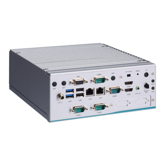
Series User’s Manual I/O Outlets The following figures show I/O outlets on the front of the eBOX640A. ⚫ Front View COM 4 (RS232) 2 x Antenna opening hole COM 3 (RS232) DC Jack power input Flexible IO Window Remote Switch connector... -
Page 18: Packing List
Fanless Embedded System with LGA1700 12th generation ® ® ® eBOX640A-ALD-S Intel Core™ i7/i5/i3 or Celeron processor, Intel H610, 4 COM, 2 LANs,2 HDMI, 4 USB, 8-CH DIO and 19VDC Please contact Axiomtek’s distributors immediately in case any abovementioned items are missing. Introduction... -
Page 19: Section 2 Hardware Installation
Series User’s Manual SECTION 2 HARDWARE INSTALLATION The eBOX640A is convenient for your various hardware configurations, such as HDD (Hard Disk Drive), SSD (Solid State Drive), Long-DIMM or PCI Express Mini Card modules. Section 2 will show how to install the hardware. - Page 20 Series User’s Manual Step 4 Remove the warning label and disengage load lever. ⚫ Disengage the load lever by pushing its hook down and then pulling it slightly outward. ⚫ Rotate the load lever to the open position at approximately 135°.
- Page 21 Series User’s Manual Step 5 Installation steps of the CPU processor ⚫ Lift the processor package from shipping media by grasping the substrate edges. ⚫ Scan the processor package gold pads for any presence of foreign material. ⚫ Locate connection 1 indicator on the processor which aligns with connection 1 indicator chamfer on the socket, and notice processor keying features that line up with posts along socket walls.
- Page 22 Series User’s Manual Step 6 Installation steps of the CPU processor Align pins of the CPU with pin holes of the socket. Be careful of the CPU’s orientation that users need to align the arrow mark on the CPU with the arrow key on the socket.
-
Page 23: Installation Of So-Dimm Memory
Series User’s Manual Installation of SO-DIMM Memory Step 1 Turn off the system and unplug the power cord. Step 2 Locate the four screws on the top heatsink used to fasten the heatsink to the chassis. Step 3 Locate the memory module, insert the gold colored contact into the socket, and push the module down until it is locked in place by the two end latches. -
Page 24: Installation Of M.2 Key E / Pci-Express Mini Card
Series User’s Manual Installation of M.2 Key E / PCI-Express Mini Card Step 1 Turn off the system and unplug the power cord. Step 2 Locate the four screws on the top heatsink used to fasten the heatsink to the chassis. - Page 25 Series User’s Manual M.2 Key E slot (2230) Step 5 Assemble the bottom cover back and fasten all screws. Hardware Installation...
-
Page 26: Installation Of The M.2 Key B Mini Card (Only For Storage)
Series User’s Manual Installation of the M.2 Key B Mini Card (only for storage) Step 1 Turn off the system, and unplug the power cord. Step 2 Turn the system upside down to locate the two screws at the rear side, and then loosen the two screws. -
Page 27: Installation Of The 2.5" Sata Device
Series User’s Manual Installation of the 2.5" SATA Device Step 1 Turn off the system, and unplug the power adaptor. Step 2 Turn the system upside down to locate the two screws at the rear side, and then loosen the two screws. - Page 28 Series User’s Manual Step 5 Connect the SSD/HDD directly and make sure the insertion is complete. PULL Hardware Installation...
-
Page 29: Section 3 Jumper & Connector Settings
Series User’s Manual SECTION 3 JUMPER & CONNECTOR SETTINGS Proper jumper settings configure the eBOX640A to meet various application needs. Hereby all jumpers settings along with their default settings are listed for devices onboard. Locations of Jumpers & Connectors MANO561 Top Side Jumper &... - Page 30 Series User’s Manual MANO561 Bottom Side 【Note】 It is strongly recommended that any unmentioned jumper settings should not be modified without instructions by Axiomtek FAEs. Any modifications without instructions might cause system failure. Jumper & Connector Settings...
-
Page 31: Summary Of Jumper Settings
Series User’s Manual Summary of Jumper Settings Proper jumper settings configure the eBOX640A to meet various application purposes. A table of all jumpers and their default settings is listed below. MANO561 Jumper Description Setting 3-5 Close COM Data/Power Select... -
Page 32: Com2 Data/Power Select (Jp1)
Series User’s Manual 3.2.1 COM2 Data/Power Select (JP1) This is a 3x2-pin (pitch=2.00mm) jumper. The COM1 port has +5V power capability on DCD and +12V on RI by setting JP1. Functions Settings Power: Set COM1 pin 1 to +5V... -
Page 33: Connectors
Connectors connect the board with other parts of the system. Loose or improper connection might cause problems. Make sure all connectors are properly and firmly connected. Here is a table summarizing all connectors on the eBOX640A series. External Connectors Sections... -
Page 34: Dc Jack Power Connector (Cn23)
Series User’s Manual 3.3.1 DC Jack Power Connector (CN23) The CN23 is a DC jack with screw supporting 19VDC power input connector. Firmly insert at least 120W adapter into this connector. Loose connection may cause system instability and make sure all components/devices are properly installed before connecting. -
Page 35: Ethernet Connector (Cn9 & Cn12)
Series User’s Manual 3.3.4 Ethernet Connector (CN9 & CN12) The motherboard comes with two high performance plug and play Ethernet interfaces (RJ-45) which are fully compliant with the IEEE 802.3 standard. Connection can be established by plugging one end of the Ethernet cable into this RJ-45 connector and the other end to a 1000/100/10-Base-T hub. -
Page 36: Com1 D-Sub Connector (Cn1)
Series User’s Manual 3.3.5 COM1 D-Sub Connector (CN1) The CN1 is a 9-pin D-Sub connector for COM1 (RS-232/422/485) serial port interfaces. The pin assignments of RS-232/422/485 are listed in table below. Baud Rate: 9600~115200. COM1: RS-422 RS-485 RS-232 (1T/1R Full... -
Page 37: Audio Jack (Cn14)
Series User’s Manual 3.3.7 Audio Jack (CN14) The motherboard provides HD audio jack for line-out on the rear I/O. Install audio driver, and then attach audio devices to CN14. Pin Color Signals Green Line-out 3.3.8 HDMI 1.4b Connector (CN6) The HDMI (High-Definition Multimedia Interface) is a compact digital interface which can transmit high-definition video and high-resolution audio over a single cable. -
Page 38: Digital I/O Connector (Cn26)
Series User’s Manual 3.3.9 Digital I/O Connector (CN26) The CN26 is a 2x5-pin (pitch=2.00mm) connector for digital I/O interface. You may use software programming to control these digital signals, please refer to Appendix Pins Signals DB9 Connector PIN Define:... -
Page 39: Fan Headers (Cn27, Cn28)(Optional)
Series User’s Manual 3.3.10 FAN headers (CN27, CN28)(optional) The motherboard has two fan headers. The fan cable and connector may be different according to the fan manufacturer. Connect the fan cable to the connector while matching the black wire to pin#1. -
Page 40: Key E Socket (Cn22)
Series User’s Manual 3.3.13 M.2 Key E Socket (CN22) The system comes with one M.2 Key E socket (PCIe & USB signal) (for Wi-Fi & Bluetooth). Pins Signals Pins Signals +3.3V_SBY USB_D+ +3.3V_SBY USB_D- M.2_BT_PCMCLK CNVI_WGR_DATA1_D- M.2_BT_PCMRST CNVI_WGR_DATA1_D+ M.2_BT_PCMIN M.2_BT_PCMOUT... - Page 41 Series User’s Manual CNVI_WT_DATA0_D- CNVI_WT_DATA0_D+ CNVI_WT_CLK_D- +3.3V_SBY CNVI_WT_CLK_D+ +3.3V_SBY Jumper & Connector Settings...
-
Page 42: Express Mini Card Slot (Cn21)
Series User’s Manual 3.3.14 Express Mini Card slot (CN21) The CN21 complies with PCI-Express Mini Card Spec. V1.2. Pins Signals Pins Signals WAKE# +3.3VAUX +1.5V CLKREQ# UIM_PWR/NC UIM_DAT/NC REFCLK- UIM_CLK/NC REFCLK+ UIM_REST/N UIM_VPP/NC PERST# PCIE_RX_D- +3.3VAUX PCIE_RX_D+ +1.5V SMB_CLK... -
Page 43: Front Panel Connector (Cn8)
Series User’s Manual 3.3.15 Front Panel Connector (CN8) The CN8 is a 2x6-pin (pitch=2.54mm) header. It includes Power-on, Reset, HDD LED and Power LED connections, allowing user to connect the PC case’s front panel switch functions. Pins Signals Pins... -
Page 44: Key B Socket (Scn1)
Series User’s Manual 3.3.16 M.2 Key B Socket (SCN1) The SCN1 is a M.2 Key B (2242) connector. It is supports the M.2 storage module via PCIe x2 Signal Signal CONFIG_3 +3.3V_SBY +3.3V_SBY Full Card PWR OFF USB_D+ USB_D-... -
Page 45: Section 4 Bios Setup Utility
Series User’s Manual SECTION 4 BIOS SETUP UTILITY This section provides users with detailed description how to set up basic system configuration through the BIOS setup utility. Starting To enter the setup screens, follow the steps below: Turn on the computer and press the <Del> key immediately. -
Page 46: Main Menu
Series User’s Manual Main Menu The Main Menu screen is the first screen users see when entering the setup utility. Users can always return to the Main setup screen by selecting the Main tab. System Time/Date can be set up as described below. The Main BIOS setup screen is also shown below. -
Page 47: Advanced Menu
Series User’s Manual Advanced Menu The Advanced menu also allows users to set configuration of the CPU and other system devices. You can select any of the items in the left frame of the screen to go to the sub menus: ►... - Page 48 Series User’s Manual ⚫ CPU Configuration This screen shows CPU information. Intel (VMX) Virtualization Technology Enable or disable Intel Virtualization Technology. When enabled, a VMM (Virtual Machine Mode) can utilize the additional hardware capabilities. It allows a platform to run multiple operating systems and applications independently, hence enabling a single computer system to work as several virtual systems.
- Page 49 Series User’s Manual ⚫ SATA Configuration During system boot up, BIOS automatically detects the presence of SATA devices. In the SATA Configuration menu, you can see all currently installed SATA device(s). SATA Controller(s) Enable or disable the SATA Controller feature.
- Page 50 Series User’s Manual ⚫ Trusted Computing This screen provides function for specifying the TPM2.0 settings. TPM Device Selection Select TPM device: ® PTT: Intel built-in TPM. Enables PTT in SkuMgr. dTPM: External extended Infineon’s TPM. Disables PTT in SkuMgr.
- Page 51 Series User’s Manual ⚫ ACPI Settings ACPI Sleep State When the suspend button is pressed, the ACPI (Advanced Configuration and Power Interface) sleep state is S3 (Suspend to RAM). Restore AC Power Loss Decide the state of system when power is re-applied after a power failure.
- Page 52 Series User’s Manual ⚫ F81966 Super IO Configuration You can use this screen to select options for the Super IO Configuration and change the value of the selected option. A description of the selected item appears on the right side of the screen.
- Page 53 Series User’s Manual ⚫ Serial Port 1 Configuration Serial Port Enable or disable serial port 1. Change Settings Select an optimal setting for Super IO device. Auto IO=3F8h, IRQ=4; IO=3F8h, IRQ=3, 4, 5, 6, 7, 9, 10, 11, 12;...
- Page 54 Series User’s Manual ⚫ Serial Port 2~4 Configuration Serial Port Enable or disable serial port 2~4. Change Settings Select an optimal setting for Super IO device. For serial port 2: Auto IO=2F8h, IRQ=3; IO=3F8h, IRQ=3, 4, 5, 6, 7, 9, 10, 11, 12;...
- Page 55 Series User’s Manual ⚫ Hardware Monitor This screen monitors hardware health status. This screen displays the temperature of system and CPU, cooling fans speed in RPM and system voltages (VCCIO, CPU SA, +5V and +12V). BIOS Setup Utility...
- Page 56 Series User’s Manual ⚫ Smart Fan Mode Configuration This screen allows you to configure Smart Fan mode. You can use Smart Fan function to control CN60 and CN61. Smart Fan Function Enable or disable Smart Fan. Fan 1 Smart Fan Control Select Smart Fan operating mode.
- Page 57 Series User’s Manual ⚫ PCI Subsystem Setting This screen allows you to set PCI Subsystem mode. BIOS Setup Utility...
- Page 58 Series User’s Manual ⚫ USB Configuration This screen shows USB configuration. USB Devices Display all detected USB devices. BIOS Setup Utility...
- Page 59 Series User’s Manual ⚫ Network Stack Configuration Network Stack Enable or disable UEFI Network Stack. BIOS Setup Utility...
- Page 60 Series User’s Manual ⚫ NVMe Configuration This screen shows NVMe device information. BIOS Setup Utility...
-
Page 61: Chipset Menu
Series User’s Manual Chipset Menu The Chipset menu allows users to change the advanced chipset settings. Users can select any of the items in the left frame of the screen to go to the sub menus: ► System Agent (SA) Configuration ►... - Page 62 Series User’s Manual ⚫ System Agent (SA) Configuration VT-d Check to enable VT-d function on MCH. Above 4GB MMIO BIOS assignment Enable/Disable above 4GB Memory Mapped IO BIOS assignment \n\n. This is enabled automatically when Aperture Size is set to 2048MB.
- Page 63 Series User’s Manual ⚫ PCH-IO Configuration This screen allows you to set PCH parameters. HD Audio Control detection of the HD Audio device. Disabled: HDA will be unconditionally disabled. Enabled: HDA will be unconditionally enabled. Auto: HDA will be enabled if present, disabled otherwise.
- Page 64 Series User’s Manual ⚫ Onboard Device Onboard LAN 1/2 Enable or disable onboard LAN 1/2. BIOS Setup Utility...
-
Page 65: Security Menu
Series User’s Manual Security Menu The Security menu allows users to change the security settings for the system. Administrator Password This item indicates whether an administrator password has been set (installed or uninstalled). User Password This item indicates whether a user password has been set (installed or uninstalled). -
Page 66: Boot Menu
Series User’s Manual Boot Menu The Boot menu allows users to change boot options of the system. Setup Prompt Timeout Number of seconds to wait for setup activation key. 65535(0xFFFF) means indefinite waiting. Bootup NumLock State Use this item to select the power-on state for the keyboard NumLock. -
Page 67: Save & Exit Menu
Series User’s Manual Save & Exit Menu The Save & Exit menu allows users to load system configuration with optimal or fail-safe default values. Discard Changes and Exit Select this option to quit Setup without making any permanent changes to the system configurations and return to Main Menu. - Page 68 Series User’s Manual This page is intentionally left blank. BIOS Setup Utility...
-
Page 69: Appendix Awatchdog Timer
Series User’s Manual APPENDIX A WATCHDOG TIMER About Watchdog Timer Software stability is major issue in most application. Some embedded systems are not watched by human for 24 hours. It is usually too slow to wait for someone to reboot when computer hangs. - Page 70 Series User’s Manual LPFNDLLSETIOSPACE lpFnDll_Set_IO; int _tmain(int argc, _TCHAR* argv[]) unit = 0; WDTtimer = 0; (hinstLibDLL == NULL) hinstLibDLL = LoadLibrary(TEXT("diodll.dll")); (hinstLibDLL == NULL) //MessageBox("Load diodll dll error", "", MB_OK); (hinstLibDLL) lpFnDll_Get_IO (LPFNDLLGETIOSPACE)GetProcAddress(GetModuleHandle("diodll.dll"), "GetIoSpaceByte"); lpFnDll_Set_IO (LPFNDLLSETIOSPACE)GetProcAddress(GetModuleHandle("diodll.dll"), "SetIoSpaceByte"); printf("Input Watch Dog Timer type, 1:Second ; 2:Minute :"...
- Page 71 Series User’s Manual lpFnDll_Set_IO(0x2f, WDTDATA); (unit == 1) lpFnDll_Set_IO(0x2e, 0xF6); lpFnDll_Set_IO(0x2f, WDTtimer); //start watchdog counting lpFnDll_Set_IO(0x2e, 0xF5); WDTDATA = lpFnDll_Get_IO(0x2f); WDTDATA = setbit(WDTDATA, 5); lpFnDll_Set_IO(0x2f, WDTDATA); else if (unit == 2) //set WDT Timer lpFnDll_Set_IO(0x2e, 0xF6); lpFnDll_Set_IO(0x2f, WDTtimer); //set watchdog time unit to min lpFnDll_Set_IO(0x2e, 0xF5);...
- Page 72 Series User’s Manual This page is intentionally left blank. Watchdog Timer...
-
Page 73: Appendix B Digital I/O
Series User’s Manual APPENDIX B Digital I/O About Digital I/O The onboard digital I/O has 8 bits. Each bit can be set to function as input or output by software programming. In default, all pins are pulled high with +5V level (according to main power). The BIOS default settings are 4 inputs and 4 outputs. - Page 74 Series User’s Manual static int DI0status = 1; static int DI1status = 1; static int DI2status = 1; static int DI3status = 1; typedef ULONG(*LPFNDLLGETIOSPACE)(ULONG); LPFNDLLGETIOSPACE lpFnDll_Get_IO; typedef void(*LPFNDLLSETIOSPACE)(ULONG, ULONG); LPFNDLLSETIOSPACE lpFnDll_Set_IO; int _tmain(int argc, _TCHAR* argv[]) (hinstLibDLL == NULL) hinstLibDLL = LoadLibrary(TEXT("diodll.dll"));...
- Page 75 Series User’s Manual lpFnDll_Set_IO(0x2e, 0x87); lpFnDll_Set_IO(0x2e, 0x87); //LDN 06 lpFnDll_Set_IO(0x2e, 0x07); lpFnDll_Set_IO(0x2f, 0x06); //set LDN06 88h =OF //88h <0> = 1 GPIO80 DO0 output mode set 1 or input mode set 0 lpFnDll_Set_IO(0x2e, 0x88); u88HData = lpFnDll_Get_IO(0x2f); u88HData = setbit(u88HData, 0);...
- Page 76 Series User’s Manual u89HData = clrbit(u89HData, 1); lpFnDll_Set_IO(0x2f, u89HData); //89 <2> = 0 lpFnDll_Set_IO(0x2e, 0x89); u89HData = lpFnDll_Get_IO(0x2f); u89HData = clrbit(u89HData, 2); lpFnDll_Set_IO(0x2f, u89HData); //89 <3> = 0 lpFnDll_Set_IO(0x2e, 0x89); u89HData = lpFnDll_Get_IO(0x2f); u89HData = clrbit(u89HData, 3); lpFnDll_Set_IO(0x2f, u89HData);...
- Page 77 Series User’s Manual (0x40 & u8AHData) //GPIO86 DI2 status DI2status = GPIO_HIGH; else DI2status = GPIO_LOW; (0x80 & u8AHData) //GPIO87 DI3 status DI3status = GPIO_HIGH; else DI3status = GPIO_LOW; ((DI0status == GPIO_LOW && DI1status == GPIO_LOW) && (DI2status GPIO_LOW &&...
Need help?
Do you have a question about the eBOX640A Series and is the answer not in the manual?
Questions and answers