Table of Contents
Advertisement
Quick Links
Advertisement
Table of Contents

Related Manuals for AXIOMTEK eBOX532-100-FL Series


Summary of Contents for AXIOMTEK eBOX532-100-FL Series
- Page 1 Series Fanless Embedded System User’s Manual...
-
Page 2: Disclaimers
Axiomtek does not make any commitment to update the information in this manual. Axiomtek reserves the right to change or revise this document and/or product at any time without notice. No part of this document may be reproduced, stored in a retrieval system, or transmitted, in any form or by any means, electronic, mechanical, photocopying, recording, or otherwise, without the prior written permission of Axiomtek Co., Ltd. -
Page 3: Safety Precautions
Safety Precautions Before getting started, please read the following important safety precautions. The eBOX532-100-FL does not come equipped with an operating system. An operating system must be loaded first before installing any software into the computer. Be sure to ground yourself to prevent static charge when installing the internal components. -
Page 4: Classification
Classification Degree of production against electric shock: not classified Degree of protection against the ingress of water: IP40 Equipment not suitable for use in the presence of a flammable anesthetic mixture with air or with oxygen or nitrous oxide. Mode of operation: Continuous Type of protection against electric shock: Class I equipment General Cleaning Tips You may need the following precautions before you begin to clean the computer. - Page 5 Cleaning Tools: Although many companies have created products to help improve the process of cleaning your computer and peripherals users can also use household items to clean their computers and peripherals. Below is a listing of items you may need or want to use while cleaning your computer or computer peripherals.
-
Page 6: Scrap Computer Recycling
For the computers that are no longer useful or no longer working well, please contact your Axiomtek distributor for recycling and we will make the proper arrangement. Trademarks Acknowledgments Axiomtek is a trademark of Axiomtek Co., Ltd. IBM, PC/AT, PS/2, VGA are trademarks of International Business Machines Corporation. ® ®... -
Page 7: Table Of Contents
Table of Contents Disclaimers ......................ii Safety Precautions ....................iii Classification ......................iv General Cleaning Tips ................... iv Scrap Computer Recycling ..................vi CHAPTER 1 INTRODUCTION ................ 1 General Description ................1 System Specifications ................ 3 1.2.1 CPU ........................3 1.2.2 I/O System ...................... - Page 8 This page is intentionally left blank. viii...
-
Page 9: Chapter 1 Introduction
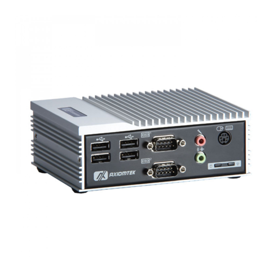
Series User’s Manual CHAPTER 1 INTRODUCTION This chapter contains general information and detailed specifications of the eBOX532-100-FL. The Chapter 1 includes the following sections: General Description System Specification Dimensions I/O Outlets Package List General Description The eBOX532-100-FL is an embedded system that supports onboard AMD G-Series single core T40R (1.0 GHz) and Fusion Controller Hub A50M that delivers outstanding system... - Page 10 Series User’s Manual O.S. Supported ® The eBOX532-100-FL supports Windows XP, Windows 7 and also supports embedded OS, ® such as Windows XP embedded and Linux. For storage device, the eBOX532-100-FL ™ supports one 2.5" SATA-600 HDD drive bay, and one type II CompactFlash slot.
-
Page 11: System Specifications
Series User’s Manual System Specifications 1.2.1 Onboard AMD G-Series APU single core T40R 1.0 GHz. System Chipset AMD Fusion Controller Hub A50M. BIOS American Megatrends Inc. UEFI (Unified Extensible Firmware Interface) BIOS ... -
Page 12: System Specification
Series User’s Manual 1.2.3 System Specification Watchdog Timer 1~255 seconds; up to 255 levels. Power Supply External AC 25W AC/DC power adapter with lock (Output: DC 5V @ 5A) Operation Temperature 0~45 ℃ (WT HDD) 0~50 ℃ (WT CF/SSD) ... -
Page 13: Dimensions
Series User’s Manual Dimensions The following diagrams show you dimensions and outlines of the eBOX532-100-VGA-FL. Introduction... - Page 14 Series User’s Manual eBOX532-100-PGA-FL. Introduction...
-
Page 15: I/O Outlets
Series User’s Manual I/O Outlets The following figures show you I/O outlets on front view of the eBOX532-100-VGA-FL & eBOX532-100-PGA-FL Front View Rear View (eBOX532-100-VGA-FL) Introduction... - Page 16 Series User’s Manual Rear View (eBOX532-100-PGA-FL) NOTE P D (DisplayPort) Module It is used for eBOX532-100-FL1.0G-PGA. 3 types of module are offered by option DisplayPort to HDMI Female Cable DP to HDMI DisplayPort to DVI Female Cable DP to DVI...
- Page 17 Series User’s Manual SATA Connector(SATA 1) SATA connector is for high-speed SATA interface ports and each SATA connector supports a single SATA device. Signal SATA_TX+ SATA_TX- SATA_RX- SATA_RX+ Plug one end of the SATA cable to the SATA connector, and the other end of cable to the SATA hard drive.
-
Page 18: Packing List
25W 5V AC/DC Power Adapter HDD Mylar x1 (Figure – Power Adapter Pin Assignment) If you can not find this package or any items are missing, please contact Axiomtek distributors immediately. NOTE P D (DisplayPort) Module It is used for eBOX532-100-FL1.0G-PGA. -
Page 19: Chapter 2 Hardware Installation
Series User’s Manual CHAPTER 2 HARDWARE INSTALLATION The eBOX532-100-FL is convenient for your various hardware configurations, such as Memory Module, HDD (Hard Disk Drive), and CompactFlash card. The chapter 2 will show you how to install the hardware. It includes:... - Page 20 Series User’s Manual Step 4 Locate the memory module as marked. Step 5 Hold one side of the module, and insert the gold colored contact into the socket. Push the module down. Step 6 The memory module is locked by two latches on the sides.
- Page 21 Series User’s Manual NOTE hile uninstalling the Memory Module, you need to stretch these two latches aside, and then take the module off the socket. Step 7 Put the cover back to the system, and fasten screws tight close the chassis.
-
Page 22: Installing The Hard Disk Drive
Series User’s Manual Installing the Hard Disk Drive The eBOX532-100-FL offers a convenient drive bay module for users to install HDD. The system offers users one 2.5” SATA-600 Hard Disk Drive for installation. Please follow the steps: Step 1 Turn off the system, and unplug the AC/DC power cord. - Page 23 Series User’s Manual Step 4 HDD assembly parts include: HDD Bracket x 1 2.5 inch HDD x 1 Screws x 4 HDD Mylar x1 Screw the 2.5 inch HDD, together with the HDD Mylar, to the HDD bracket.
-
Page 24: Installing The Compactflash Card
Series User’s Manual Installing the CompactFlash Card Step 1 Turn off the system, and unplug the AC/DC power cord. Step 2 Turn the system upside down to locate screws at the bottom. Step 3 Loosen these screws, and remove the back cover from the system. - Page 25 Series User’s Manual Step 4 Locate the CompactFlash socket. Step 5 Insert the CompactFlash card into the socket until it is firmly seated. Hardware Installation...
- Page 26 Series User’s Manual Step 6 Put the cover back to the system, and fasten screws tight close the chassis. Hardware Installation...
-
Page 27: Installing Din Mount (Optional)
Series User’s Manual Installing DIN Mount (optional) The eBOX532-100-FL provides DIN Mount that customers can install as below: Step 1 Prepare DIN Mount assembling components (screws and bracket) ready. MAXIMUM DEPTH OF THE HDD BRACKET: 2.5mm DEPTH 2.5mm MAX. - Page 28 Series User’s Manual Step 2 Assembly the bracket to the system, and fasten screws tight. Hardware Installation...
-
Page 29: Installing Rail Mount
Series User’s Manual Installing Rail Mount The eBOX532-100-FL provides Rail Mount that customers can install as below: Step 1 Prepare Rail Mount assembling components (screws and bracket) ready. Step 2 Assembly the bracket to the system, and fasten screws tight. - Page 30 Series User’s Manual This page is intentionally left blank. Hardware Installation...
-
Page 31: Chapter 3 Ami Bios Setup Utility
Series User’s Manual CHAPTER 3 AMI BIOS Setup Utility The AMI UEFI BIOS provides users with a built-in setup program to modify basic system configuration. All configured parameters are stored in a 16MB flash chip to save the setup information whenever the power is turned off. -
Page 32: Navigation Keys
Series User’s Manual Navigation Keys The BIOS setup/utility uses a key-based navigation system called hot keys. Most of the BIOS setup utility hot keys can be used at any time during the setup navigation process. These keys include <F1>, <F2>, <Enter>, <ESC>, <Arrow> keys, and so on. -
Page 33: Main Menu
Series User’s Manual Main Menu When you first enter the setup utility, you will enter the Main setup screen. You can always return to the Main setup screen by selecting the Main tab. System Time/Date can be set up as described below. -
Page 34: Advanced Menu
Series User’s Manual Advanced Menu Launch PXE OpROM Use this item to enable or disable the boot ROM function of the onboard LAN chip when the system boots up. The Advanced menu also allows users to set configuration of the CPU and other system devices. - Page 35 Series User’s Manual ACPI Settings You can use this screen to select options for the ACPI configuration, and change the value of the selected option. A description of the selected item appears on the right side of the screen.
- Page 36 Series User’s Manual CPU Configuration This screen shows the CPU Configuration, and you can change the value of the selected option. Node 0 Information View memory information related to Node 0. AMI BIOS Setup Utility...
- Page 37 Series User’s Manual IDE Configuration In the IDE Configuration menu, you can see the currently installed hardware in the SATA ports. During system boot up, the BIOS automatically detects the presence of SATA devices. AMI BIOS Setup Utility...
- Page 38 Series User’s Manual USB Configuration You can use this screen to select options for the USB Configuration, and change the value of the selected option. A description of the selected item appears on the right side of the screen.
- Page 39 Series User’s Manual F81801 Super IO Configuration Serial Port Configuration The configurations of serial port 0~1 are set “Enabled” as default. AMI BIOS Setup Utility...
- Page 40 Series User’s Manual F81801 H/W Monitor This screen monitors hardware health. This screen displays the CPU temperature, system temperature and system voltages (VIN0, VIN1 and VBAT). AMI BIOS Setup Utility...
-
Page 41: Chipset Menu
Series User’s Manual Chipset Menu The Chipset menu allows users to change the advanced chipset settings. You can select any of the items in the left frame of the screen to go to the sub menus: ► North Bridge ►... - Page 42 Series User’s Manual North Bridge Configuration This screen allows users to configure parameters of North Bridge chipset. AMI BIOS Setup Utility...
- Page 43 Series User’s Manual Memory Configuration Integrated Graphics The Integrated Graphics controller configuration is set to “Auto”. Node 0 Information This item is to provide user with the information of current using DDR3 SDRAM . AMI BIOS Setup Utility...
- Page 44 Series User’s Manual North Bridge LVDS Config Select DP0 Output Mode Use this item to enable or disable LVDS. LVDS Panel Config Select Use this item to select configuration for LVDS panel if DP0 Output Mode is enabled.
- Page 45 Series User’s Manual South Bridge This screen allows users to configure South Bridge chipset. For items marked with “”, please press <Enter> for more options. ► SB SATA Configuration ► SB USB Configuration ► SB HD Azalia Configuration...
- Page 46 Series User’s Manual SB SATA Configuration Use this item to select option for SATA configuration. OnChip SATA Channel Use this item to enable or disable SATA channel. OnChip SATA Type Here are the options: Native IDE and AHCI.
- Page 47 Series User’s Manual SB USB Configuration Use this item to enable or disable all USB devices. SB HD Azalia Configuration This item allows you to enable or disable HD audio Azalia device. AMI BIOS Setup Utility...
-
Page 48: Boot Menu
Series User’s Manual Boot Menu The Boot menu allows users to change boot options of the system. Setup Prompt Timeout Number of seconds to wait for setup activation key. 65535(0xFFFF) means indefinite waiting. Bootup NumLock State Use this item to select the power-on state for the NumLock. -
Page 49: Security Menu
Series User’s Manual Security Menu The Security menu allows users to change the security settings for the system. Administrator Password This item indicates whether an administrator password has been set (installed or uninstalled). User Password This item indicates whether an user password has been set (installed or uninstalled). -
Page 50: Save & Exit Menu
Series User’s Manual Save & Exit Menu The Save & Exit menu allows users to load your system configuration with optimal or fail-safe default values. Save Changes and Exit When you have completed the system configuration changes, select this option to leave Setup and return to Main Menu. - Page 51 Series User’s Manual Discard Changes and Reset Select this option to quit Setup without making any permanent cha nges to the system configuration and reboot the computer. Select Discard Changes and Reset from the Save & Exit menu and press <Enter>. Select Yes to discard changes and reset.
- Page 52 Series User’s Manual This page is intentionally left blank. AMI BIOS Setup Utility...
-
Page 53: Appendix A Watchdog Timer
Series User’s Manual APPENDIX A Watchdog Timer About Watchdog Timer Software stability is major issue in most application. Some embedded systems are not watched by human for 24 hours. It is usually too slow to wait for someone to reboot when computer hangs. - Page 54 Series User’s Manual Begin Begin Next Next Enable and Initialize Enable and Initialize Watchdog Timer Watchdog Timer Next Next Program “A” Program “A” Next Next Disable Watchdog Reset Watchdog Timer Timer Next Next Warchdog Timer...
-
Page 55: Sample Program
Series User’s Manual Sample Program Assembly sample code : ;Enable WDT: dx,2Eh al,87 ;Un-lock super I/O dx,al dx,al ;Select Logic device: dx,2Eh al,07h dx,al dx,2Fh al,07h dx,al ;WDT Device Enable: dx,2Eh al,30h dx,al dx,2Fh al,01h dx,al ;Activate WDT: dx,2Eh... - Page 56 Series User’s Manual dx,al dx,2Fh al,Mh ;M=00h,01h,...FFh (hex),Value=0 to 255 Note dx,al ;(see below ;Set Second or Minute : dx,2Eh al,0F5h dx,al dx,2Fh al,Nh ;N=71h or 79h(see below Note dx,al Warchdog Timer...
- Page 57 Series User’s Manual ;Disable WDT: dx,2Eh al,30h dx,al dx,2Fh al,00h ;Can be disabled at any time dx,al Note: If N=71h, the time base is set to second. M = time value 00: Time-out disable 01: Time-out occurs after 1 second...
- Page 58 Series User’s Manual This page is intentionally left blank. Warchdog Timer...
Need help?
Do you have a question about the eBOX532-100-FL Series and is the answer not in the manual?
Questions and answers